Where is the Stator on a Motorcycle? Your Guide to Finding and Understanding This Key Component
Every design engineer and every hands-on rider eventually hits the same question. Where is the stator on a motorcycle and why does it matter? If you suspect a charging problem or you are mapping out a better motor design with improved motor laminations and heat management this guide will walk you through both the practical and the engineering details. We will start with location and function. Then we will open the cover and talk materials, laminations, and manufacturing decisions that drive reliability, cost, and performance.
Before we dive in a quick note on vocabulary. In motorcycle terms people often say “alternator.” On most modern bikes the alternator is a permanent magnet alternator made up of a stationary stator coil stack and a rotating flywheel with embedded magnets. The stator produces AC current. A rectifier/regulator (often called the RR) converts that AC current to DC current and maintains the battery at a safe charge voltage.
In short the stator sits at the heart of the motorcycle electrical system. It powers the charging system when the engine runs. When it fails you see dim headlights, a dead or dying battery, engine sputtering at low RPM, or a bike that won’t start.
Now let’s answer the location question clearly then build to the engineering fundamentals and the procurement choices behind a solid stator design.
In This Article
- Why Location Matters and the Fast Answer
- The Motorcycle Charging System in Plain English
- Inside the Stator: Laminations, Materials, and Core Losses
- Variations by Bike Type and Brand
- Accessing, Inspecting, and Replacing a Stator
- Diagnosing Charging Failures with a Multimeter
- Material and Manufacturing Options for Stator Core Laminations
- Which Option Fits Your Application
- Procurement, Reliability, and Cost Considerations
- Your Engineering Takeaway
Why Location Matters and the Fast Answer
Problem
You have a motorcycle that is not charging. Maybe your battery keeps dying or the lights go dim at idle. You know the stator might be the culprit but you are not sure where to find it. For engineers and procurement managers the question often hides a deeper design point. Where and how the stator sits drives cooling, reliability, manufacturability, and service cost.
Fast Answer
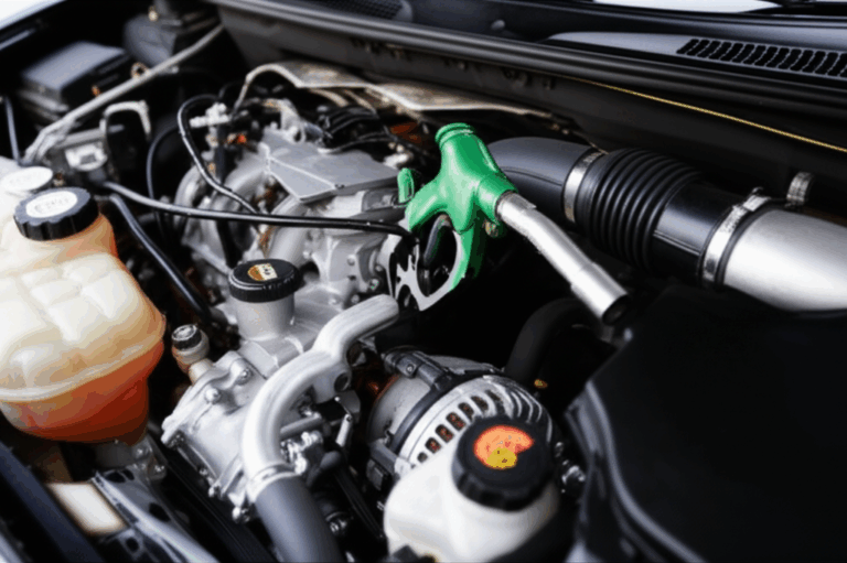
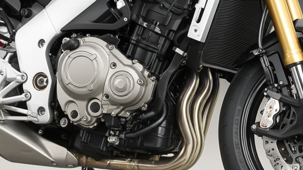
On the vast majority of motorcycles the stator sits inside the engine on the left-hand side when you are sitting on the bike. It is bolted to the inside of a left side engine cover that many people call the stator cover or alternator cover. You can spot the cover from the outside by a rubber grommet and a short wiring harness exiting the cover and heading toward the rectifier/regulator. That harness is your breadcrumb trail.
Why this placement
The stator must sit very close to the flywheel. The flywheel contains strong permanent magnets. The rotor and stator work as a pair. As the engine spins the rotor’s magnets sweep past the stator windings and generate AC current. Most manufacturers place the flywheel on the left end of the crankshaft for packaging and service reasons so the stator lives there too. It sits in engine oil for splash cooling on many models which helps control overheating stator conditions that lead to burnt stator windings.
Exceptions exist. Some scooters and a few models route the alternator to the right side engine cover for packaging or balance. Certain dirt bikes use a smaller magneto motorcycle setup with a simpler source coil and pickup coil under a narrow side cover. Always check the service manual for your model to confirm location, torque specs, and the exact stator wiring diagram.
The Motorcycle Charging System in Plain English
Explain
Let’s demystify the motorcycle electrical system. It is simple compared to a car yet it carries a few twists that matter for design and diagnostics.
- Permanent Magnet Alternator (PMA): Most modern bikes use a permanent magnet alternator. The flywheel (rotor) has fixed magnets. The stator coil stack sits stationary. This PMA generates AC voltage any time the engine spins. There is no field coil to excite.
- Rectifier/Regulator (RR): The RR converts AC to DC and clamps the battery voltage to a safe range. A healthy system will show 13.8 to 14.8 volts DC at the battery at 3,000 to 5,000 RPM. A failing RR can overcharge or undercharge which can cook a stator or leave a battery flat.
- Battery: The battery buffers load and provides cranking current. If your battery is weak a good stator cannot save you at idle. Use a battery load test before blaming the stator.
- Ignition System: On many carbureted dirt bikes or older street bikes a source coil and a pulse generator motorcycle sensor (pickup coil) feed a CDI unit for spark. On fuel injected bikes the ECU/ECM commands spark through a transistorized ignition (TI) module. Weak stator output or a bad pickup coil can cause no spark problems or engine misfire complaints.
How current flows
The stator generates AC current. Those alternating currents leave via three equal wires on a three phase stator or via two wires on a single phase stator. They run to the RR. The RR turns them into the DC current that charges your battery and runs the bike. Any drop on that path due to bad connectors, ground wires, fuses, or relay issues will look like battery charging issues even if the stator is fine.
A quick analogy for engineers who like pictures. Imagine the flywheel magnets as a rotating water wheel and the stator laminations as sluice gates. As magnets sweep past coils they push electrons just like paddles push water. The RR is your spillway. It regulates the level so the pond (the battery) stays full but not flooded.
Inside the Stator: Laminations, Materials, and Core Losses
Explain
Under the cover the stator is not just “copper wire.” The core is a stack of thin insulated electrical steel laminations. These laminations give the magnetic circuit shape and path. They constrain flux so your copper generates power efficiently. Laminations also control losses and heat which directly affect stator lifespan and warranty risk.
- Why laminations: Changing magnetic fields induce eddy currents in steel. Those currents waste energy as heat. Thin insulated laminations break those currents into tiny loops. Smaller loops mean less heat. Think eddy currents like whirlpools in a river. Laminations act like baffles that break big whirlpools into ripples.
- Hysteresis loss: Magnetizing a steel core and then demagnetizing it over and over takes energy. Materials with lower coercivity reduce this hysteresis loss and run cooler at a given frequency.
- Permeability: Materials with higher magnetic permeability guide flux more easily which allows more compact stator designs or higher AC voltage output at the same RPM.
- Thickness: Lamination thickness is a trade-off. Thinner laminations reduce eddy current loss as frequency rises. They can raise cost and can demand tighter tooling or laser programs.
Material choices
For motorcycle alternators that operate in the low to mid kHz range at peak RPM non-oriented silicon steels (M grades) are common. They balance cost and performance. Some high-performance applications favor premium low-loss grades. Rare high-frequency systems and aerospace drives sometimes lean toward cobalt alloys for higher saturation flux density yet cobalt cost drives total cost of ownership.
If you want a quick overview of industry options and specs you can scan the fundamentals of electrical steel laminations. It covers common grades and use cases without vendor hype.
Core construction
The stator core typically uses either interlocking features like tabs, bonding, or welding. Interlocking laminations behave like LEGO bricks. They snap together and build a stiff core without heat input. Welding can distort the B-H curve because heat can change local microstructure. Bonding preserves magnetic properties and improves NVH since it damps vibration but it adds process steps.
For BLDC traction motors the considerations look similar yet geometry and slot design change. If you work on EV motorcycles or e-bikes you will want to compare a traditional PMA stator stack to a dedicated bldc stator core and its slot/pole choices. Geometry drives copper fill factor and torque ripple which shows up as rough idle analogs in combustion bikes or audible whine in EVs.
Variations by Bike Type and Brand
Guide
Even if the engineering stays the same the location and packaging differ by brand and model. Here is how to find the stator and what to expect.
- Sportbikes and naked bikes: Honda CBR, Yamaha R6, Kawasaki Ninja, and Suzuki GSXR models usually carry a prominent alternator cover on the lower-left engine casing. A short wire bundle exits at the rear of the cover and runs to the RR. Honda places the CBR stator on the left in most years. Yamaha R6 stator location sits behind the left alternator cover. Kawasaki Ninja stator hides in the left crankcase cover. Suzuki GSXR stator does the same.
- Cruisers: Harley-Davidson and large Japanese cruisers often integrate the stator behind a round or oval chrome cover on the left. The RR location varies but the harness cue still helps. On many Harleys the stator lives behind the primary cover and bathes in oil which helps heat management at low speed.
- Dirt bikes and off-road: Many use a compact magneto ignition system with a source coil, pickup coil, and lighting coils under a narrow left cover. The system can be single phase. Space is tight and sealing is critical for off-road duty.
- Scooters: Packaging varies with horizontal engines and CVT housings. The stator still sits near the flywheel inside a side cover. Access may require removing body panels.
- Exceptions: A few engines put the alternator on the right side engine cover due to gear train layout. Certain vintage designs mount external generators or run stand-alone magnetos yet modern street motorcycles rarely do.
To confirm location on your exact bike check the service manual and the parts fiche. The service manual stator location diagrams, electrical system diagram, and component layout drawings remove any guesswork. The parts fiche stator page helps you find gasket part numbers and torque specs in one place.
Accessing, Inspecting, and Replacing a Stator
Guide
You found the cover. Now what. Here is a compact and practical path for inspection or DIY stator replacement that respects engineering best practice.
Preparation checklist
- Tools for stator replacement: Socket set, Allen/Hex bits, torque wrench, flywheel puller tool if needed, impact wrench for the flywheel nut if your model requires removal, crank holding tool, plastic scraper for gasket removal, liquid gasket sealant if specified, multimeter, and a load tester for the battery.
- Safety: Disconnect the battery. Keep rags and a catch pan ready.
- Oil: Plan for an oil change stator repair operation. Many covers sit below the oil level. Drain engine oil before you pull the cover unless the service manual says otherwise.
- Workspace: Remove fairings as needed. Photograph routing of the wiring harness for reassembly.
Core steps
1) Disconnect the RR and stator harness connectors. Inspect for heat or corrosion.
2) Remove the left engine cover or alternator cover bolts in a crisscross pattern. Note bolt lengths.
3) Gently pry the cover free. Avoid gouging the crankcase cover mating surface.
4) If your model requires flywheel removal to free the stator use the specified flywheel puller tool. Do not substitute a harmonic balancer puller unless the manual permits it. Use an impact wrench to loosen a stubborn flywheel nut if needed yet protect threads and crank.
5) Remove the stator bolts and lift the stator assembly.
6) Inspect the gasket. Replace it. Stator gasket installation needs a clean surface. Some OEMs specify liquid gasket sealant at certain joints. Follow that.
7) Clean and reassemble. Torque specifications for the stator cover and stator bolts matter. Use a torque wrench and follow the service manual.
Warnings and pro tips
- Do not pinch the wiring harness as you refit the cover.
- Replace O-rings on wire pass-through grommets if they seep.
- If the stator sits in an oil bath use the correct engine oil grade. Oil flow helps cooling which fights overheating stator failures.
DIY or professional
DIY stator replacement is very doable with patience and the right tools. A shop will charge two to five hours of labor. Professional motorcycle repair cost for parts and labor ranges from a few hundred dollars to over a thousand on some sportbikes or exotics. If your time is tight or the model uses press-fit parts hire a mechanic. You will spend money but avoid risk to the crankcase.
Diagnosing Charging Failures with a Multimeter
Guide
Before you spend on parts confirm the diagnosis with electrical troubleshooting. Many battery charging issues trace to a bad RR, bad grounds, or simple connector and fuse faults. Here is a solid path.
Start with the battery
- Battery load test: Verify the battery can hold voltage under load. Clean the battery terminals and check ground wires first. A weak battery causes motorcycle won’t start complaints even with a good stator.
- Parasitic drain motorcycle check: With the bike off measure current draw at the battery. Too much draw hints at a relay or accessory issue.
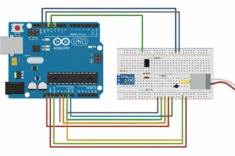
Check system voltage
- Voltmeter testing motorcycle: With the engine running measure DC voltage at the battery at idle and at 3,000 to 5,000 RPM. You want 13.8 to 14.8 VDC at speed. If voltage never rises above 12.8 VDC suspect the stator or RR. If it climbs past 15 VDC suspect the RR.
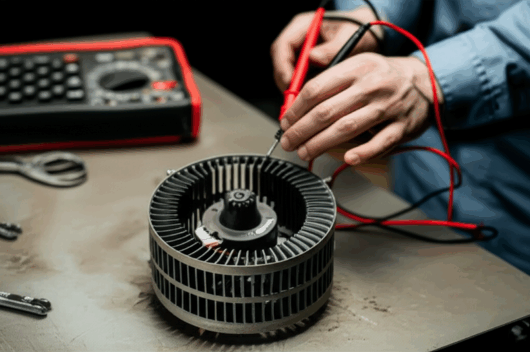
Test the stator directly
- Unplug the stator from the RR. Measure AC voltage across each pair on a three phase stator (A-B, B-C, C-A). At 5,000 RPM a healthy system often shows 40 to 70+ VAC per phase depending on design. Values vary by model so use the service manual.
- Ohm test stator: With the engine off measure resistance values stator phase to phase. You should see low equal resistance across pairs. Measure continuity to ground from each stator lead. You want no continuity to ground. An open circuit or a short circuit to ground flags a bad stator.
- Continuity test stator: Wiggle the harness while measuring. Intermittent opens in a wiring harness can mimic failure on the bench.
- Pickup coil and source coil: If you have no spark test the pickup coil and source coil resistances and AC output while cranking. A weak source coil underdrives the CDI. A dead pickup coil kills engine timing and spark.
Check the RR and wiring
- Voltage regulator rectifier symptoms: Overheating, melted connectors, and uneven DC output. Test the RR’s diode function with an ohmmeter if your manual provides values.
- Inspect fuses motorcycle electrical and perform relay troubleshooting motorcycle when you see odd intermittent faults. Check grounds from engine to chassis and from RR to battery.
Quick sanity checks that often fix the symptom
- Wiring harness inspection for chafed wires.
- Clean up grounds and battery terminals.
- Replace corroded connectors. Hot connectors drop voltage and burn stators over time.
What “good” looks like
When the stator passes AC voltage output tests and the battery sees 14.2 VDC at 4,000 RPM with a solid headlight load you can stop chasing the stator. Focus on the RR and the harness.
Material and Manufacturing Options for Stator Core Laminations
Guide
Now let’s pivot to the design and sourcing questions that engineers and procurement teams care about. The stator is a lamination stack that must balance performance, heat, and cost. You have choices. Here is an impartial overview.
Material considerations
- Non-oriented silicon steels (M grades): The default for most motorcycle charging systems. Good magnetic permeability. Balanced hysteresis and eddy current losses at the operating frequency. Familiar supply chain and consistent quality. If you want a deep dive you can scan typical options for silicon steel laminations.
- Premium low-loss grades: Lower core loss for the same thickness which helps when you push output at lower RPM without adding heat. Price increases. Justify with thermal margin or space savings.
- Cobalt alloys: Higher saturation flux density and good high-temperature performance. Used in aerospace or very high power density machines. Expensive. Use only if the business case demands it.
- Electrical steel coatings: Insulation coatings on each lamination manage interlaminar resistance. Coating class selection matters for bonding compatibility and punchability.
Manufacturing and assembly processes
- Progressive die stamping: Best for high-volume production. Lowest cost per part after tooling. Tooling is expensive and long lead. Edge quality is excellent. Edge burr control protects interlaminar insulation. A stamp shop that holds flatness and slot-to-tooth concentricity helps reduce runout in the completed stator core lamination.
- Laser cutting: Best for prototyping, pre-production, or complex low-volume designs with short lead times. Thermal input increases the heat-affected zone which can raise local loss at edges. Good process control and post-process stress relief mitigate the effect for many geometries.
- Wire EDM: Very accurate edges. Slow and costly. Rare for production yet useful for master proofing.
- Interlocking vs welding vs bonding: Interlocking speeds assembly and avoids heat input. Welding adds rigidity yet can harm magnetic properties. Bonding reduces vibration and creates a rigid core without heat which helps NVH and loss but adds process time and consumables.
- Stack height control: Tight control of stack height and squareness helps air-gap uniformity. It drives consistent AC voltage output at a given RPM.
System integration
- Air gap: The gap between rotor and stator needs consistency. Too tight risks rubbing. Too wide bleeds flux and drops output so you may see dim headlights motorcycle complaints at idle.
- Slot geometry and copper fill: Slot shape affects copper packing factor and resistance. Better fill reduces I²R loss. That is free efficiency and lower heat.
- Heat path: Oil-splash cooling and conduction to the left side engine cover pull heat out. If the stator runs hot at idle consider RR changes or airflow tweaks. Heat management engine decisions save the stator from insulation breakdown.
For a broad view of assemblies and options see motor core laminations. It frames how stacks, coatings, and processes come together in a motor or generator program.
Which Option Fits Your Application
Guide
Let’s match options to use cases in straight talk.
- High-volume motorcycle charging systems: Progressive die stamping of non-oriented silicon steel laminations with interlocking features. Proven path. Lowest cost at volume. Use bonding if NVH or oil-borne vibration calls for it.
- Low-volume or performance variants: Laser cut laminations for quick turns and design iterations. Upgrade to low-loss steel grades if thermal margin runs thin. Shift to interlocking as volumes firm up.
- Small off-road magneto systems: Simplify. Choose robust coatings and conservative slot fills. Off-road dirt and water demand robust potting or varnish on windings. Emphasize sealing and strain relief on the harness.
- High-power accessories or touring bikes: Consider a three phase stator with increased slot fill and a larger rotor with improved airflow. Pair with a quality RR to avoid cooking the system in city traffic.
- BLDC traction drives for EV motorcycles: Different game. Optimize the lamination stack for torque density and minimized core loss. Select a rotor core lamination strategy that matches your magnet topology and mechanical needs. Manage skew and slot/pole combinations to suppress cogging torque which feels like rough idle in an ICE bike.
Honest limitations
- Laser cutting is fantastic for prototypes and complex shapes. It is not your lowest-cost path for 100k units.
- Welding is rugged and simple. It can raise loss if not controlled.
- Bonding wins on performance. It requires a well-controlled process and clean surfaces.
- Premium steel lowers core loss. It raises unit cost. Validate the ROI through cooler operation and longer stator lifespan motorcycle metrics.
Procurement, Reliability, and Cost Considerations
Guide
Engineers design for performance. Procurement must land a reliable supply at the right price and lead time. Both sides want to avoid rework and warranty hits. Here is a checklist you can use together.
Technical checklist
- Target losses: Define max core loss at your operating frequency and flux density. Include hysteresis loss and eddy current loss in the spec.
- Tolerances: Lock down stack height, slot dimensions, circular runout, and air-gap targets.
- Insulation: Define coating class and thermal class for varnish. Oil exposure matters.
- Test methods: Specify acceptance tests. Resistance checks of coils. Hi-pot tests. Impedance targets at frequency. Align with IEC 60034 frameworks when applicable.
- RR pairing: Approve RR options. Many OEMs use Shindengen units. A mismatched RR drives overheating stator failures.
- System validation: Plan thermal testing at idle in hot soak conditions. City traffic kills many systems due to low airflow. Watch for insulation breakdown stator signs.
Supplier checklist
- Process control: Ask for run charts on thickness, burr height, and stack squareness.
- Material traceability: Require heat numbers and coating class documentation. Many teams lean on ASTM and JIS references for electrical steel and coatings.
- Warranty on motorcycle parts: Clarify terms. RR and stator often fail in pairs. Coordinate policies to avoid finger-pointing.
- Logistics: Ensure packaging prevents edge damage. Laminations with chipped coatings create ground paths that lead to premature failure.
Cost snapshot
- Cost of stator replacement parts: OEM units often land between $200 and $600. Exotic bikes can run higher. Aftermarket options range from $80 to $300.
- Reliability of aftermarket stators: Reputable brands such as Rick’s Motorsport Electrics and Electrosport offer solid units with improved potting or upgraded wire enamel. Do your homework. Cheap units often skimp on copper fill or lamination quality.
- Labor: Two to five hours depending on bodywork and flywheel removal steps. Total professional motorcycle repair cost typically lands between $400 and $1,100 all-in.
Preventative maintenance stator
- Keep connectors clean and tight. Replace fried RR connectors.
- Route harnesses away from sharp edges. Tie them down.
- Use fresh engine oil that matches the spec since oil cooled stator setups need flow.
- Monitor battery health. A dying battery stresses charging components.
The Practical Location Guide You Came For
Explain and Guide
Let’s tie the engineering back to the driveway task. Here is the short practical guide to stator location and identification.
- Look left first: Sit on the bike and scan the left side engine cover. The alternator cover often shows a larger circular or teardrop shape with a rubber grommet at the rear where the wiring exits.
- Follow the wire: That harness runs forward or upward to the RR. The RR usually sits in an airflow path under the fairing or along the frame. Rectifier regulator location varies by model yet the harness path makes it easy to spot both components.
- Confirm by brand: Honda CBR, Yamaha R6, Kawasaki Ninja, Suzuki GSXR, and many Triumph and Ducati models keep the stator behind the left cover. Harley-Davidson hides it behind the primary cover on the left. Scooters vary. Check the service manual stator location page or the motorcycle engine diagram in your manual when in doubt.
- Watch for exceptions: A handful of engines place the alternator on the right side engine cover for packaging. The visible harness exit still gives it away.
What it looks like inside
Once you pull the cover you will see a circular stator with many copper windings around a laminated core. The core is the stator core lamination stack. The running flywheel rotor sits opposite with magnets arranged around the inner circumference. Burnt stator windings, dark brown varnish, or a cooked smell point to overheating. Inspect closely at the bottom of the windings where oil tends to sit since that is where hot spots often bloom.
Stator vs Generator vs Alternator: Clearing the Terms
Explain
- Stator vs generator: “Generator” is a generic term for a device that converts mechanical power into electrical power. A stator is the stationary part inside that device. On motorcycles we most often use a stator with a permanent magnet rotor which makes an alternator.
- Stator vs alternator in automotive context: Many cars use wound-field alternators where the rotor has an electromagnet. A regulator controls field current. Motorcycles almost always use a permanent magnet alternator instead. No field wire. Simpler yet less controllable at very low RPM.
Symptoms of a Bad Stator and Related Issues
Guide
You do not open the engine cover for fun. You open it because the bike is unhappy. Here are the most common symptoms and how they map to causes.
Charging system issues
- Battery drain motorcycle or battery not charging questions: Battery voltage never rises above 13 VDC when revved. The bike dies on a long ride at night. Possible stator failure or RR failure or both.
- Dim headlights motorcycle at idle: Normal at very low RPM on some bikes. If it persists at 3,000 RPM check stator AC output and RR.
- Motorcycle won’t start after a ride: Battery discharges while riding due to charging failure.
Performance problems
- Engine sputtering motorcycle or rough idle motorcycle: Weak charging can drag ECU voltage down. On CDI systems a weak source coil can cause misfire.
- Troubleshooting motorcycle no spark: Check pickup coil, source coil, CDI unit, ECM/ECU power, and grounds. The stator can be fine while a failed pickup coil kills spark. On TI systems a dead crank sensor mimics the same symptom.
Visual and olfactory cues
- Burnt smell under the cover.
- Discolored windings or melted potting.
- Charred connectors at the RR or stator leads.
Remember a bad RR can cook a stator. A bad stator can overload an RR. Test the whole charging system as a set. Replace both if in doubt and if the history shows repeated failures.
“What’s Really Going On” with Core Losses: A Short Engineering Sidebar
Explain
At the root of many stator failures sits heat. Heat comes from copper losses and core losses. Copper loss scales with current squared so high load heats copper quickly. Core loss splits into hysteresis and eddy currents.
- Hysteresis: Every time the magnetic field swings up and down the steel expends energy due to its internal magnetic friction. Materials with lower coercivity waste less energy. That is why better grades cost more but run cooler.
- Eddy currents: Changing magnetic fields induce currents inside the steel. Laminations capped with insulation act like dams that block large loops. Thinner laminations break loops into smaller cusps. Less heating.
Engineers counter losses with better electrical steel, thinner laminations, tighter slots that pack more copper, and better cooling through oil flow. Procurement supports the plan with suppliers that can hold burr control and coating integrity. The design pays off when you see steady battery voltage on the voltmeter and no smell of cooked varnish after a traffic jam.
Standards and References You Can Trust
Empower
If you want to go deeper without swimming in jargon here are dependable anchors.
- IEC 60034 series for rotating electrical machines offers methods and definitions that help align test plans across suppliers.
- ASTM and JIS standards for non-oriented electrical steels and coating classes give material control.
- IEEE papers and tutorials on core losses summarize hysteresis and eddy current modeling for designers who want the math.
You do not need to cite chapter and verse on every drawing. You do want common references so vendors interpret the same requirements the same way.
Procurement and Design Collaboration: A Short Playbook
Guide
- Start with the electrical requirement. AC voltage output stator targets at specific RPM and load.
- Translate to geometry. Slot count, tooth width, stack height, and air gap. Use a motor simulation or vendor sizing guide.
- Pick material and thickness. Use loss curves at your frequency to set a lamination thickness. Balance core loss and cost.
- Define manufacturing. Stamping for volume. Laser cutting for speed. Interlock, weld, or bond based on NVH and performance.
- Lock down testing. Resistance values stator, hi-pot, induced voltage, and loaded thermal test. Include an RR performance check.
- Plan for service. Write a clear stator wiring diagram and component layout for the service manual. Publish torque specs and gasket details. Engineers save money when field techs can fix failures quickly.
Frequently Asked Practical Questions
- Why is my motorcycle battery not charging? Start with the battery and RR. Then test stator AC output. Check grounds and connectors. Many “bad stator” claims turn out to be RR or harness faults.
- Internal vs external stator: Modern street bikes use internal stators inside the engine cover for protection and cooling. External setups show up on small engines and some generators.
- Do I need a flywheel puller tool? Many bikes allow stator removal without pulling the flywheel. If the service manual calls for removal use the correct puller. A wrong puller can damage the crank.
- Can I use liquid gasket sealant? Use it only where the manual specifies. Too much squeeze-out can contaminate oil passages.
- Which RR brand is reliable? Many OEMs use Shindengen regulators. Quality aftermarket units exist. Match phase type and current rating to your stator.
- OEM stator vs aftermarket: OEM costs more with consistent quality. Aftermarket can save money. Reputable brands like Rick’s Motorsport Electrics and Electrosport often improve heat tolerance. Avoid mystery units with poor reviews.
When Materials and Process Drive Reliability: One Realistic Scenario
A sportbike rides hard in summer traffic. The RR sits behind a fairing panel with poor airflow. The stator bathes in hot oil. The bike spends twenty minutes at idle after a long highway run. Core loss and copper loss pile up and windings soak. Insulation softens. Varnish cracks over time. The next high RPM blast puts stress on a few turns. A tiny short circuit forms between adjacent coils which increases current in one phase. Heat skyrockets and the rider smells varnish. The bike shows dim lights at idle and the voltmeter reads 12.5 VDC at 4,000 RPM. That is a bad day.
How do you prevent it
- Lower core loss with a better steel grade or thinner laminations.
- Improve airflow to the RR. Move it to cleaner air. Add a heatsink path to frame.
- Reduce harness drop. Clean connectors and grounds.
- Consider a three phase stator if the bike uses single phase.
- Publish a maintenance note that encourages riders to keep oil level correct since oil cooled stators need flow.
Your Engineering Takeaway
Empower
Here is the bottom line distilled into crisp points you can act on.
- Location: The stator sits inside the engine behind a side cover almost always on the left. Follow the harness to the RR to confirm.
- Function: It generates AC which the RR converts to DC. Healthy systems put 13.8 to 14.8 VDC at the battery at speed.
- Diagnostics: Test AC voltage per phase. Check resistance and isolation to ground. Verify RR function and battery health. Inspect connectors, fuses, relays, and grounds.
- Materials: Stator cores are stacks of thin insulated electrical steel laminations. Thinner and better grades reduce losses and heat.
- Manufacturing: Stamp for volume. Laser cut for agility. Interlock or bond cores for performance. Control burrs and stack height for consistent output.
- Application fit: Choose materials and processes based on volume, frequency, and thermal margin. Dirt bikes need robust sealing. Touring bikes need thermal headroom.
- Cost and reliability: Pair stator and RR choices. Use reputable parts. Confirm warranty terms with suppliers.
- Next step: If you need help choosing lamination material, thickness, and assembly for your stator program review options for core lamination stacks and align your spec with a proven supplier. For design trade-offs across stator and rotor stacks study both sides of the magnetic circuit early.
If you want a quick technical review of your stator or alternator concept share your target AC output, space claim, and expected duty cycle. We will map material and process options, estimate core loss and temperature rise, and help you select a balanced solution that keeps riders out of trouble and keeps your warranty line quiet.