Where Is the Stator Located on an ATV? And What That Teaches Us About Stator Core Laminations, Materials, and Manufacturing Choices
Every design engineer faces a similar moment. You need to hit an efficiency target, keep thermal rise in check, and still make the budget work. You also need a product that survives the field. If you work on powersports, robotics, appliances, or industrial drives, you’ve likely stared at a stator core and asked two questions. Where is it, exactly, in the final machine? What lamination decisions will move the needle on performance and cost?
Let’s use a practical hook many engineers search for—where is the stator located on an ATV—to anchor a deeper engineering discussion. The ATV example gives you a clear mental model for how stator core laminations sit in the system, how electromagnetic fundamentals drive losses, and how material plus manufacturing choices shape outcomes. We will answer the location question. Then we will guide you through the “why” and “how” behind stator and rotor lamination design so you can specify with confidence.
In This Article
- Why location matters: the ATV stator and the system view
- The engineering fundamentals: core losses, flux, and lamination thickness
- Materials overview: silicon steels, cobalt alloys, and when to use each
- Manufacturing and assembly: stamping, laser, bonding, interlocks, and quality control
- Best-fit selection by application: frequency, torque density, heat, and cost
- ATV stator location, access, and diagnostics: a practical field guide
- Testing and specs: what to measure and which standards matter
- Procurement playbook: DFM, tolerances, coatings, and total cost
- Your engineering takeaway and next steps
Part 1: Why Location Matters—The ATV Stator and the System View
Problem. You need to locate an ATV stator fast, diagnose charging or spark issues, and decide whether to repair or redesign. You also want to understand how the hidden lamination stack under that engine cover affects output, heat, and reliability.
Here’s the quick answer for the field technician and the design engineer.
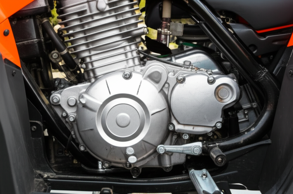
- Where is the stator located on an ATV? It sits inside the engine, almost always on the left side when you’re seated on the quad. It hides under the magneto or flywheel cover, bolted to the engine case. The flywheel or rotor spins around it. You’ll see a bundle of stator output wires (typically 2–5) exiting the engine case through a rubber grommet that runs to the regulator rectifier and the wiring harness.
- Why that location matters to laminations. The stator’s lamination stack lives in a hot, vibrating environment near oil. Material choice, lamination thickness, insulation coating, and assembly method set the table for core loss, temperature, durability, and charging performance. This is not a theoretical choice. It is a real lever on reliability and cost.
If you design BLDC or AC machines for other industries, the lesson holds. The stator core lamination and rotor core lamination choices you make must fit the mounting and thermal realities of the application. Geometry, slot fill, frequency content, and duty cycle combine with the environment to dictate the best material and process.
Before we explore materials and processes, ground yourself in the physics.
Part 2: What’s Really Going On? The Engineering Fundamentals
Think of eddy currents like small, unwanted whirlpools in a river. A changing magnetic field induces circulating currents in conductive materials. Those whirlpools create heat and waste energy. Laminations break the whirlpools into tiny eddies that do less harm. That’s the core idea.
Three pillars drive magnetic core behavior.
- Eddy current loss. Proportional to the square of thickness and frequency squared under classical approximations. Thinner laminations and good interlaminar insulation lower eddy losses. Laser cutting can introduce a heat-affected zone that increases effective conductivity at the edges which raises loss unless you anneal or control settings.
- Hysteresis loss. Driven by the material’s B-H curve and coercivity, which is the material’s resistance to demagnetization. Materials with lower coercivity and optimized microstructure reduce hysteresis loss at a given peak flux density.
- Saturation and permeability. Magnetic permeability tells you how easily flux flows through the core much like a sponge soaks up water. Saturation flux density limits torque or power density before the core tops out and performance flattens or distorts.
How it applies in an ATV magneto or a small alternator:
- The stator is stationary. The flywheel or rotor carries permanent magnets or a magneto assembly. As the rotor spins, it sweeps the stator teeth which induces AC in the coils. The regulator rectifier converts AC to DC and charges the battery. Some ignition systems still use a CDI (capacitor discharge ignition) that can draw power from a dedicated alternator coil or pickup coil on the stator.
- Frequency increases with engine RPM. Higher frequency raises eddy losses. If you want better charging at idle without cooking the stator at high RPM, you must balance lamination thickness, wire gauge, and thermal path.
Put bluntly. The stator core lamination is a quiet workhorse. It shapes flux paths, sets core loss, and backs up copper. Get it right and you hit your system targets with margin.
Part 3: Your Options Explained—Materials and Processes That Move the Needle
Here’s a balanced guide to the materials and manufacturing choices that matter most.
Material considerations
- Nonoriented silicon steel (NOES) M-grades
- Use: General purpose rotating machines and motor core laminations. Common grades include M19, M27, M36, and M47. Higher M numbers are thicker and higher loss. M19 29 gauge (0.36 mm) or thinner grades serve higher frequency and lower loss applications.
- Pros: Widely available, predictable magnetic properties, cost effective, broad supplier base, compatible with stamping or laser.
- Cons: Higher loss than cobalt-iron at high flux density. May need thinner laminations for high frequency which raises cost.
- Grain-oriented silicon steel (GOES)
- Use: Transformer lamination core and EI core or UI lamination core stacks where the flux is aligned with the rolling direction. Not a good fit for most rotating machines due to anisotropy in properties.
- Pros: Very low loss along the rolling direction. Great for transformer cores and CRGO lamination core applications.
- Cons: Poor cross-grain performance. Limited benefit in stators which see multi-directional flux.
- Cobalt-iron alloys (e.g., 49% Co)
- Use: High power density, high temperature, aerospace, and high-frequency machines that push flux density.
- Pros: Higher saturation flux density and lower core loss at elevated frequencies. Strong candidate for compact machines where every gram counts.
- Cons: Expensive and challenging to process. Laser cutting or EDM can work for prototypes. Hard tooling for stamping costs more and demands tight process control.
- Low-loss advanced NOES
- Use: High-efficiency industrial motors, EV traction motors, and BLDC designs that need low iron loss across a wide speed range.
- Pros: Improved loss curves without full cobalt cost. Available with excellent insulation coatings.
- Cons: Price premium over commodity NOES. Longer lead times in tight markets.
- Soft magnetic composites (SMC)
- Use: 3D flux designs and novel topologies. Powder-based with insulating binders to block eddies in three dimensions.
- Pros: Excellent for complex flux paths with low eddy currents. Can simplify manufacturing for certain shapes.
- Cons: Lower permeability and saturation compared to laminated steels. Mechanical properties and thermal conductivity differ from sheet steel stacks.
If you want a refresher on categories and geometry, this overview of electrical steel laminations offers a useful baseline for materials and typical use cases.
Manufacturing and assembly processes
- Stamping vs. laser cutting vs. wire EDM
- Stamping: Best for volume. Low per-part cost after you invest in progressive dies. Control burr height, maintain flatness, and specify grain orientation for GOES parts when relevant. Burr orientation matters because sharp edges raise local loss and risk insulation breakdown.
- Laser cutting: Great for prototypes and small batches. Flexible with no tooling. Watch the heat-affected zone which increases loss. Consider a post-cut stress relief anneal if material and design allow.
- Wire EDM: Excellent precision. No HAZ. Slow and costly for volume but ideal for tight tolerances and difficult materials.
- Stacking and joining methods
- Interlocking: Think LEGO bricks. Tabs and slots lock laminations into a rigid stack without welding which avoids heat that can degrade magnetic properties.
- Bonding: Polymer or inorganic bonding between layers improves rigidity and can raise vibration resistance. It also reduces hum. Bonding can improve stacking factor.
- Riveting, cleating, welding: Mechanical options exist for rotor and stator stacks. Use sparingly in high-performance cores to preserve magnetic properties.
- Insulation coatings and stacking factor
- Coatings: Phosphate inorganic, C-3, C-5, and other classes exist. You want enough dielectric strength to prevent interlaminar eddies without adding too much thickness that hurts stacking factor.
- Stacking factor: Ratio of steel height to stack height. Higher is better for flux carrying steel area. Coating thickness and surface roughness affect it.
- Tolerances that matter
- Slot geometry and tooth tip radius affect localized flux density. Tight slot tolerances optimize copper fill and reduce AC copper losses.
- Skew and step-skew reduce cogging and torque ripple. They need process control in stamping and stacking.
- Burr height control protects insulation and keeps loss in check. A simple rule of thumb is to keep burrs below 10% of lamination thickness unless you have test data that supports more.
If you need a broad look at motor stack design, the primer on motor core laminations can help align requirements across stators and rotors. For rotor design decisions, this quick reference on rotor core lamination is useful when you balance cage design, magnet pockets, and mechanical strength.
Part 4: Which Application Is This For? Matching Choices to Need
- Low-speed high-torque machines
- You can use thicker laminations and save on cost because dominant frequency content is lower. Copper loss and thermal path may matter more than core loss.
- High-frequency or wide-speed-range machines
- Go thinner on laminations. Consider low-loss NOES or cobalt-iron. Watch mechanical resonance and noise when you reduce thickness.
- High temperature environments
- Prioritize insulation class and coating stability. Use materials that keep loss curves predictable at elevated temperature. Consider bonding to improve vibration resistance.
- Compact BLDC outrunners and inrunners
- Tight slot pitch and high pole counts raise frequency at a given RPM. Advanced low-loss NOES or cobalt-iron can justify cost. Tolerances around magnet slots and tooth tips drive cogging and acoustic performance. If you design compact brushless machines, bookmark this resource on bldc stator core.
Laser cutting offers exceptional precision and shines in prototyping or complex low-volume designs. It will not beat stamping cost in high-volume runs with simple geometries. If your team plans to scale, make sure the stamped geometry gives you the same electromagnetic result as the laser prototype. A small change in tooth tip shape can alter flux density and iron loss.
Part 5: ATV Stator Location, Access, and Diagnostics—A Practical Field Guide
You came here for a direct answer. Let’s deliver, then go deeper so engineers, techs, and buyers can share a common language.
The stator’s precise hiding spot
- Under the magneto or flywheel cover. The stator is an internal component. You won’t see it on the exterior. The flywheel spins outside it and induces current.
- Left side of the engine. Most ATVs place the generator or magneto assembly on the left when you’re seated. There are exceptions. The general rule holds across Honda, Yamaha, Polaris, Kawasaki, Suzuki, Can-Am, Arctic Cat, Kymco, and TGB.
- Behind the flywheel. The flywheel bolts to the crankshaft. It rotates around the stator’s stationary coils and the laminated core.
- Wiring connection. Look for a sealed rubber grommet where the stator output wires exit the engine case. Those leads run to the regulator rectifier and the main wiring harness.
Visual cues help. Identify the engine side cover that people call the generator cover or stator cover. You’ll often find it on the lower-front or side of the engine. Find the bundle of 2–5 wires that emerge from a grommet. Those are your stator output wires and pickup coil leads.
Engineers and product designers, note what this means for lamination choices. The environment is oily, hot, and vibratory. The stator core lamination stack must maintain interlaminar integrity and bonding or interlocks must hold under thermal cycling. The insulation system must shrug off oil contact and heat. If you want a concise design perspective on this specific core, this overview of stator core lamination is on point.
If you produce documentation, consider including a diagram that highlights the generator cover, flywheel, and stator behind it. A simple sectioned view with arrows speeds diagnosis on the shop floor.
Why teams look for the stator in the first place
- Battery not charging. The most common complaint. An ATV battery not charging points you toward the charging system. The stator and the regulator rectifier are prime suspects.
- ATV not starting or weak spark. Some systems use the stator to generate ignition power for the CDI box. A bad alternator coil or pickup coil can cause a no spark condition.
- Dim or flickering lights and accessories. Indicates low or inconsistent output.
- General electrical system failure. Use a charging system schematic or an ATV electrical system diagram to map the fault.
Accessing the stator: the quick overview
- Safety. Disconnect the battery. Let the engine cool. Use PPE. Keep a clean bench because you’ll deal with oil and a gasket.
- Drain oil. Some ATV models require an oil drain before you remove the stator side cover. The service manual tells you. Plan to replace oil and the stator gasket.
- Remove the engine side cover. Loosen the cover bolts in a star pattern. Carefully separate the cover. Use plastic or wood to avoid marring surfaces. Watch the magnet pull on the flywheel and the cover alignment dowels.
- Pull the flywheel. You will need a model-specific flywheel puller and sometimes a flywheel holder or stopper tool. Do not pry or hammer. You can damage the crankshaft or the flywheel key.
- Unbolt the stator. Once exposed, the stator will be bolted to the case. Disconnect its output leads and pickup coil connector.
- Reassembly. Replace the gasket or use approved RTV sealant if spec’d. Torque bolts to spec. Route wires through the grommet properly and inspect oil seals.
Always consult the ATV electrical service manual for exact steps, torque specs, and specialty tool requirements. The right tools reduce risk and time. The wrong move can bend a crank or crack a cover.
Testing and troubleshooting (engineers and techs speak the same language here)
You can test a suspected stator with a multimeter. Follow a simple stator voltage test procedure.
- Resistance (ohmmeter) tests. Check stator coil resistance and compare it to the stator resistance specifications in the manual. Open circuit or short to ground indicates failure.
- AC output tests. With the engine running, measure stator output voltage between phases or leads. You’ll see AC voltage rise with RPM. The service manual gives setpoints.
- Continuity. A stator wire continuity test confirms lead integrity through the wiring harness.
- Visual inspection. Discoloration, scorched windings, or melted insulation point to overheating. That aligns with the primary failure mechanism we see in the field.
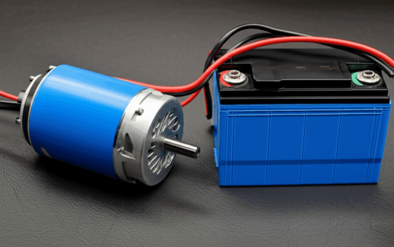
How does the ATV charging system work? The stator generates AC which goes to the regulator rectifier. The rectifier converts AC to DC then regulates it to charge the battery and power loads. The CDI or ECU handles ignition timing. A pickup coil or pulsar coil sends a position signal to the CDI or ECU which fires the ignition coils and spark plug.
If you need to check the rest of the system:
- Find the regulator rectifier location. It is usually mounted near airflow with a heatsink. Follow the stator wires from the grommet to the rectifier. Then trace to the battery.
- Inspect the wiring harness. Look for chafing, shorts to ground, or loose connectors. Map the harness to the ATV charging system components using the schematic.
- Verify the battery. A dead battery can mask issues or cause false conclusions. Load test it. Replace if it fails.
What fails and why
Common failure frequency increases in ATVs over five years old or with high mileage. Heat and vibration degrade insulation. Overheating causes winding insulation breakdown and shorts between turns or phases. You may find scorched or discolored windings. The stator sits next to the engine. It sees oil splash and hot soak. It pays to design with thermal and mechanical margin.
Costs and effort
- Replacement parts. Aftermarket stator kits often range from $75 to $250. OEM stator assemblies can cost $180 to $600 or more depending on brand and model.
- Labor. Professional replacement often takes 2.5 to 5 labor hours. With shop rates between $90 and $160 per hour, labor runs roughly $225 to $800 plus parts.
- Tools. A flywheel puller runs $25 to $70. A flywheel holder runs $20 to $50. You need a torque wrench for reassembly.
- Gasket and fluids. Plan to replace the stator cover gasket and oil. Some models need coolant if the cover carries a water passage. Expect $20 to $70 for consumables.
DIY replacement can save 50% to 75% of the total repair cost. Accurate diagnosis prevents parts darts. Start with simple tests and a service manual.
Model-specific variations and best practices
- Brands. Honda, Yamaha, Polaris, Kawasaki, Suzuki, Can-Am, Arctic Cat, Kymco, and TGB share the same general architecture. The left side cover houses the magneto. Wire colors and connectors vary by manufacturer.
- Design. Some ATVs use a single-phase stator with two output leads. Others use a three-phase stator with three yellow output wires. Identify your stator output phases and stator output leads before testing.
- Tools and specs. A flywheel key and specific puller size are model dependent. Torque specs differ. Read the repair manual. It is not optional if you want a first-time-right outcome.
ATV stator quick-reference FAQs for engineers and techs
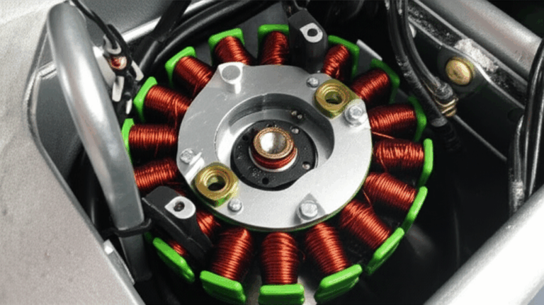
- What is an ATV stator? It is the stationary alternator coil assembly with a laminated core that generates AC power for charging and sometimes ignition.
- Where is the magneto on an ATV? Under the engine side cover around the flywheel which is the magneto assembly.
- Where is the rectifier located on an ATV? Usually near airflow on the frame with cooling fins. Follow the stator output wires to find the regulator rectifier location.
- How to find stator on ATV? Look for the stator side cover on the left. Find the wiring harness exit grommet with 2–5 wires.
- Stator behind flywheel ATV? Yes. The flywheel rotates around the stator which sits bolted to the engine case behind the flywheel.
- ATV engine cover stator and stator side cover ATV? Those terms refer to the left engine cover that hides the stator housing and magneto cover.
- Stator Gasket ATV and RTV sealant? Replace the gasket. Use sealant only if the manual calls for it. Do not overdo RTV which can clog oil passages.
- Magneto cover removal ATV and flywheel removal tools ATV? Use the correct puller and a holder. Do not pry or hammer.
- Stator output voltage ATV and stator coil resistance ATV? Measure with a multimeter. Compare to the ATV electrical service manual specs.
- Symptoms of bad ATV stator? Battery not charging, no spark, dim or flickering lights, or a charging system light if equipped.
- How to test ATV stator and stator testing with multimeter ATV? Perform resistance and AC output tests. Check for shorts to ground.
- Stator wire continuity test? Yes. Verify continuity from stator to regulator and CDI or ECU connections.
- Alternator vs stator ATV? The stator is the stationary part of the alternator. The flywheel or rotor spins around it.
- How does an ATV charging system work? Stator AC feeds the regulator rectifier. The rectifier outputs DC to the battery and loads.
- Where are the ignition coils on an ATV? Usually mounted on the frame. The CDI drives them. The pickup coil on the stator sends timing signals.
- Stator output wires ATV and ATV stator wiring colors? Follow model-specific wiring diagrams. Common three-phase wires are yellow. Grounds and pickups vary.
- Pulsar coil location ATV and pickup coil ATV? Mounted on the stator plate. It reads the flywheel trigger to time spark.
- ATV CDI box location? Typically near the frame under bodywork. Wire bundles from the stator and pickup coil feed it.
- ATV charging system schematic and ATV wiring diagram stator? Use the repair manual or manufacturer’s service info. It shortens diagnostic time.
- Stator output phases ATV, three phase stator ATV, single phase stator ATV? Identify before testing. Three-phase units have three outputs of similar AC voltage. Single-phase units have two leads.
- Stator problems diagnosis ATV and ATV electrical troubleshooting guide? Start with battery and grounds. Then test stator, regulator rectifier, and harness.
- Stator overheating ATV and why ATV stator fails prematurely? Heat, vibration, high RPM, and poor connections raise loss and temperature. Oil contamination on connectors also hurts performance.
- OEM ATV stator vs aftermarket? OEM often fits and lasts. Aftermarket can be cost effective. Match specs and check winding quality and insulation.
- Stator replacement difficulty ATV and tools needed for ATV stator replacement? Moderate difficulty. Needs a flywheel puller, holder, torque wrench, and a multimeter.
- Stator test without engine running? You can measure resistance to check for shorts or opens. You cannot verify AC output without rotation.
- Battery drain ATV stator and ATV dead battery causes? A shorted rectifier can drain the battery. Parasitic loads, weak battery, or short circuits also cause drain.
- How to clean ATV stator? Wipe with lint-free cloth. Do not soak insulation. Avoid solvents that attack varnish or coating.
- Stator rewind ATV? Possible for some models. Weigh time and cost against replacement.
- Generator coil ATV and alternator coil ATV? Same concept. The stator has multiple coils that generate AC.
- Stator housing ATV and engine cover? The cover holds the magneto space and routes the stator wires through a grommet to the wiring harness.
- Flywheel key ATV? Keeps timing alignment. Replace if sheared. A sheared key can cause no spark or misfire.
- What powers the spark plug on an ATV? The ignition coil transforms voltage driven by the CDI or ECU. Power source comes from the stator on many systems or from the battery in DC-CDI systems.
- ATV charging system parts? Stator, flywheel, regulator rectifier, battery, wiring harness, grounds, and sometimes a charging system light.
- How to diagnose a no spark condition ATV? Check kill switch, battery, grounds, pickup coil, CDI, ignition coil, and stator alternator coils.
- ATV electrical system check and electrical system fault finding? Use a methodical approach with a multimeter. Follow the schematic. Confirm grounds and connections.
Engineers and buyers, a note on root causes. The stator’s lamination stack and winding design influence heat and margins. Superior materials and coatings plus a robust assembly process reduce premature failure. You see the result as lower core loss, steadier output at idle, and longer service life.
Part 6: Testing and Specs—What To Measure and Which Standards Matter
When you qualify materials or a new lamination supplier, align on test methods and data formats. Do not rely on marketing numbers without context.
- Core loss and permeability
- Use standardized single-sheet or Epstein frame testing. The IEC 60404 series defines methods for magnetic properties of electrical steels. Ask for loss at your target peak induction and frequency. Get B-H curves not just a single number at 50 or 60 Hz.
- Insulation coatings
- Require coating class, thickness range, dielectric strength, and stacking factor data. Confirm the coating survives your assembly temperature and any post-processing like bonding or annealing.
- Dimensional tolerances
- Specify slot widths, tooth tip radii, OD/ID, burr height, and flatness. Confirm measurement methods and sample frequency.
- Process effects
- If you laser cut prototypes then stamp production, do a correlation study. Quantify loss differences. Decide if you need a stress relief anneal for laser cut parts.
- Environmental and regulatory compliance
- Confirm RoHS and REACH compliance. Request material certifications and traceability. For automotive-grade programs, PPAP or equivalent documentation helps you lock in process control.
If your application crosses into transformer duty, match material to flux direction. GOES for transformer lamination core with EI core or UI lamination core stacks makes sense. For rotating machines, stick with NOES or specialty alloys that handle multi-directional flux.
Part 7: Procurement Playbook—DFM, Tolerances, Coatings, and Total Cost
Here’s how to buy smart without surprises.
- Write a drawing that speaks the language of performance. Include lamination thickness, grade, coating class, slot tolerances, burr limits, and stack height targets. Define inspection methods. If you want a skew, show it clearly.
- Think in systems. A cheaper steel with higher loss can raise winding temperature which shortens insulation life then raises warranty cost. Consider the total cost of ownership.
- Lock in process capability. Ask for Cpk data on critical dimensions. Review control plans for stamping, deburring, coating application, and stacking. Validate stack compression methods for consistency.
- Plan the scale curve. If you prototype with laser then run volume with dies, align geometry early. Bring your supplier into the design loop so you avoid costly die changes.
- Test early with your real waveforms. Your inverter or CDI may add harmonics that change loss. Verify iron loss with test coupons or sample stacks at operating flux density and frequency content.
- Protect supply. Dual-source critical grades if risk is high. Keep a buffer on long-lead specialty steels like cobalt-iron.
When you need a single home page to orient stakeholders across the stack landscape, this quick overview of core lamination stacks helps non-specialists understand the major building blocks fast.
Part 8: How the ATV Lesson Maps Back to Lamination Design
Let’s close the loop. That hidden ATV stator teaches three durable lessons for any motor designer or procurement manager.
- The environment drives the material and process. Oil, heat, and vibration punish weak insulation and loose stacks. Choose coatings and joining methods that hold under real loads.
- Frequency content and RPM shape lamination thickness. Idle charging needs flux at low speed. High-RPM running raises eddy loss. Pick a thickness and grade that balances both.
- Assembly details change performance. Burrs, slot tolerances, skew, and bonding show up as heat, noise, and efficiency. Small decisions add up.
If you build compact brushless machines, you already live in this trade space. Slot geometry, magnet grade, and lamination loss form a triangle. Move one corner and the others move. Document your priorities then choose the steel and process that solve the right problem.
Your Engineering Takeaway
- Stator location on an ATV
- It sits under the magneto or flywheel cover on the left side of the engine behind the flywheel with output wires exiting through a grommet to the regulator rectifier and wiring harness.
- Core fundamentals
- Eddy currents act like electrical whirlpools. Thin, insulated laminations break them up and reduce loss. Hysteresis loss depends on the B-H curve and coercivity. Saturation caps your flux density and torque.
- Materials
- Use nonoriented silicon steel for most rotating machines. Consider low-loss grades or cobalt-iron for high frequency or high power density. Use grain-oriented steel for transformers not for most motors.
- Manufacturing
- Stamp for volume. Laser or EDM for prototypes and complex low-volume parts. Control burrs, coatings, and stacking. Interlocking and bonding can improve rigidity and reduce hum.
- Application fit
- Match lamination thickness and grade to frequency, temperature, and cost targets. Validate with data at your operating points.
- ATV diagnostic essentials
- Test stator coil resistance and AC output. Inspect for shorts and overheating. Use the correct flywheel puller and replace gaskets. Check regulator rectifier, battery, and grounds before you buy parts.
- Procurement
- Specify the drawing details that matter. Use IEC 60404 methods for magnetic properties. Correlate laser prototypes to stamped production. Buy for total cost of ownership not unit cost alone.
Next steps:
- If you’re scoping a new stator or rotor stack, align on your target flux density, frequency, and thermal limits. Pick two candidate steels and thicknesses. Prototype with laser. Measure loss at your waveforms. Then lock in stamping geometry and coatings.
- If you’re troubleshooting an ATV charging issue, confirm battery health, test stator resistance and AC output, verify regulator rectifier function, and inspect the harness. Plan your tool list before you open the cover.
If you want a compact reference for lamination categories and common design choices, keep these on hand:
- A primer on electrical steel laminations
- A design-focused overview of stator core lamination
- A broad look at motor core laminations
- A rotor-centric guide to rotor core lamination
- A targeted view for brushless designs via bldc stator core
You know the problem. You understand the physics. You have a clear path through material and process tradeoffs. You also know exactly where the stator hides on an ATV. Now you can make the call with confidence.