Where Is the Stator Located in a Torque Converter? My Clear, Hands-On Guide
Table of Contents
- Introduction: The quick answer you came for
- The stator’s exact location inside a torque converter
- How I visualize the assembly: a simple mental diagram
- Why the stator matters: torque multiplication and efficiency
- What the stator does at low speed vs high speed
- How the stator interacts with the impeller, turbine, and one-way clutch
- Common issues when the stator or its one-way clutch fails
- Real-world diagnosis: what I check first
- Stator design details: blades, angles, and clutch types
- Performance and application differences: stall speed and vehicle use
- Don’t confuse this stator with electric motor stators
- FAQs I answer all the time
- Quick maintenance and prevention tips
- Final thoughts: location and purpose in one tidy package
Introduction: The quick answer you came for
When people ask me where the stator sits in a torque converter I keep the answer simple. The stator sits in the middle of the converter between the impeller (the pump) and the turbine. It mounts on a fixed support sleeve that sticks out of the transmission’s front pump. A one-way clutch locks it in one direction and lets it freewheel in the other. That’s the whole trick.
Now let me unpack that in plain English. I’ll show you where to “see” it in your head. I’ll explain why its position isn’t random. I’ll also share how I diagnose stator issues in the real world when customers complain about poor acceleration, overheating, or shudder.
The stator’s exact location inside a torque converter
Here’s the clean, direct description I use with new techs.
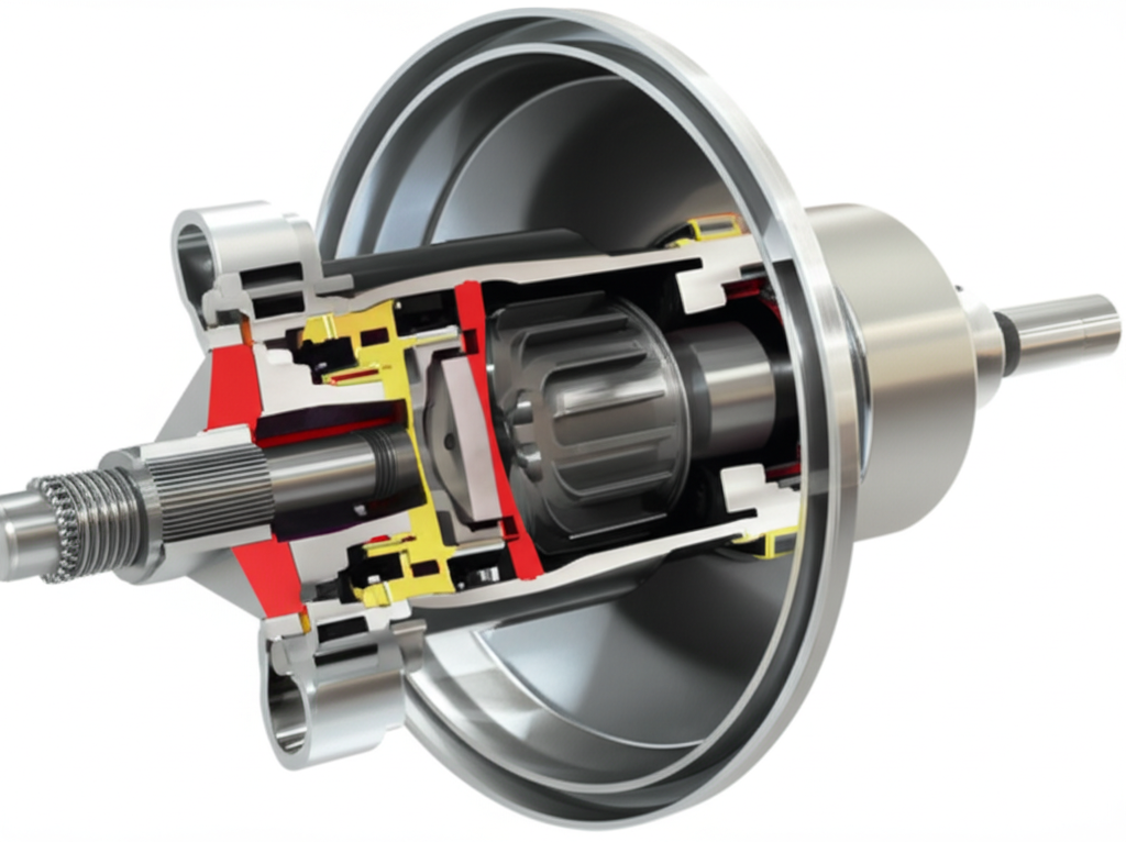
- Physical placement: The stator lives between the impeller and the turbine near the converter’s centerline. Think of it as the middle gatekeeper that manipulates the returning fluid.
- Mounting point: It rides on the stator support sleeve. That sleeve is part of the transmission pump assembly. The sleeve does not rotate with engine speed.
- Connection method: A one-way clutch (sprag or roller) connects the stator to the support. The clutch locks the stator against rotation in one direction during low-speed operation then allows it to freewheel as speeds rise.
- Relationship to the engine and transmission: The impeller is bolted to the converter housing which bolts to the flexplate on the engine crankshaft. The turbine splines to the transmission input shaft. The stator sits between those two and references the stationary transmission case through its support and clutch.
In short, it’s central and fixed on a support. The impeller spins with the engine. The turbine spins with the input shaft. The stator sits between them and plays traffic cop for fluid flow.
How I visualize the assembly: a simple mental diagram
I like a simple mental picture. Hold a donut in your hand. The outer ring is the converter housing with the impeller welded to it. Inside that flows the turbine which catches fluid like a windmill. Now picture a third set of blades in the center on a hub. Those are the stator vanes. They face the turbine on one side and the impeller on the other.
- The stator sits on a fixed hub in the center.
- The impeller slings fluid outward due to centrifugal force.
- The turbine catches that flow and sends torque into the input shaft.
- The fluid then returns toward the center where the stator redirects it.
- At low speed the stator stands its ground. At high speed it spins out of the way.
No drawings needed. That mental diagram gets you 90% of the way there.
Why the stator matters: torque multiplication and efficiency
Location dictates purpose. The stator’s position between the impeller and turbine lets it redirect returning fluid into the impeller in a favorable direction. That redirection pushes on the impeller in the same direction it already wants to spin which multiplies torque at stall. Without the stator the torque converter would act like a simple fluid coupling with no torque multiplication.
Typical torque multiplication lands around 1.8:1 to 2.5:1 at stall for many OEM converters. Performance applications tweak stator design and stall speed to go higher or lower. That’s not marketing fluff. It’s fluid dynamics. Angle the stator vanes differently and you change the flow path which changes torque multiplication and efficiency.
The stator’s central location makes this redirection efficient. It sees the returning fluid at the right moment and at the right angle. Move it away from the center and you break the geometry that makes the converter work.
What the stator does at low speed vs high speed
This is where that one-way clutch earns its keep.
- Low speed or stall: The turbine turns slowly. The stator’s one-way clutch locks it against rotation. The stator vanes kick returning fluid into the impeller in the helpful direction. You get torque multiplication and stronger launch.
- Coupling phase or higher vehicle speeds: Turbine speed rises and approaches impeller speed. Fluid now hits the stator from the other side. The one-way clutch lets the stator freewheel. That prevents the stator from fighting the flow at cruise. Freewheeling reduces fluid shear and heat.
If the converter has a lock-up clutch the transmission will command it on during steady cruise. At that point the impeller and turbine get tied together mechanically through the converter clutch. The stator still freewheels as needed. No torque multiplication then. Just direct drive plus lighter internal fluid motion.
How the stator interacts with the impeller, turbine, and one-way clutch
Let me explain power flow in simple steps.
The one-way clutch is small yet it’s the boss. Sprag or roller types both exist. A failing sprag clutch can cause either continuous locking at cruise or continuous freewheeling at launch. Both are bad for performance and heat management.
Common issues when the stator or its one-way clutch fails
In my experience most stator problems are clutch problems. Here’s what I watch for.
- Overheating transmission: A stator that stays locked at cruise whips the fluid the wrong way and shears it which makes heat. You’ll see rising transmission fluid temperature and possibly boiling ATF or burnt smell.
- Poor acceleration or a “sluggish” feel: If the stator freewheels when it should lock you lose torque multiplication. The car launches like it’s stuck in thick mud. Engine revs climb but the vehicle feels lazy.
- Converter shudder or harshness: Inconsistent fluid redirection can show up as shudder under light throttle or during shifts. Many drivers blame the lock-up clutch for every shudder. The stator can play a role too.
- Reduced fuel economy: A stator that won’t freewheel at cruise adds drag. Engines work harder to maintain speed which costs 1–3 MPG in some cases.
- Noise and vibration: Damaged blades or a failing thrust washer can add vibration issues. Converter balancing problems multiply the effect.
- Codes and warnings: You may see a check engine light. DTCs like P0740 point to the torque converter clutch circuit. That code doesn’t accuse the stator directly. It still shows you the converter is in the neighborhood of the problem.
If I see any of these, I look hard at ATF temperature and lock-up behavior. I also listen for change in noise when the transmission commands the converter clutch.
Real-world diagnosis: what I check first
I keep diagnosis simple and safe. Hydraulics and fluid dynamics can fool you if you jump to conclusions.
- ATF condition: I pull the dipstick if the vehicle has one. I check color, smell, and presence of debris. Burnt fluid tells me the converter has been making heat. Metal flakes hint at internal wear or a failing sprag clutch.
- Temperature: I monitor ATF temperature during a road test. A converter that runs hot at cruise makes me think stator freewheel failure or lock-up clutch issues. An auxiliary transmission cooler often buys time but it won’t fix a bad stator.
- Lock-up behavior: With a scan tool I look for commanded lock-up vs actual slip. I want to see the converter clutch apply at steady speed. If lock-up never applies the stator suffers more fluid shear which multiplies heat and can cloud the symptoms.
- Launch feel: I do gentle launch tests. If the vehicle revs cleanly but doesn’t pull like it should I suspect loss of torque multiplication. That puts the stator’s one-way clutch on the suspect list.
- Noise during coasting or light throttle: A stator that locks or unlocks erratically can change fluid flow and produce a faint rumble or shudder right at the coupling phase.
I don’t recommend extended stall tests on modern transmissions. You can overheat ATF in seconds which risks the converter and the front pump. Use data and your ears. Heat is the enemy. The stator is often the accomplice.
Stator design details: blades, angles, and clutch types
The stator’s job seems simple. Its design is anything but. Three elements matter most.
- Blade geometry: Stator vanes have a specific shape and angle. That geometry sets the torque multiplication ratio and the efficiency curve. Change the angle and you change how aggressively the stator redirects flow.
- One-way clutch design: Sprag clutches use shaped elements that wedge between races. Roller clutches use rollers with a ramp. Both types can wear or seize. Either failure changes how and when the stator locks.
- Materials and build: OEM and aftermarket converters vary. Some stator blades are cast and then machined. Others are stamped and welded. Quality of welds, clearances, internal seals, and thrust washers affects durability. Converter balancing also matters at highway speeds.
Performance converters often combine a more aggressive stator with a higher stall speed. Heavy duty applications tend to favor durability and heat control over maximum multiplication. You choose based on vehicle application, torque curve, and driveline goals.
Performance and application differences: stall speed and vehicle use
I match converters to how the vehicle lives.
- High stall converter: Useful when engine torque comes in higher on the rpm band. Think performance cams or turbo setups. A more aggressive stator design can help launch without bogging the engine.
- Low stall converter: Better for towing or daily driving where you want early coupling and cooler operation.
- Heavy duty vs light duty: Trucks that tow or work hard benefit from conservative stator designs plus an upgraded transmission cooler. City commuters appreciate a design that couples early and saves fuel.
OEMs like General Motors, Ford, Toyota, Honda, Nissan, ZF, Aisin, BorgWarner, and LuK balance emissions control, fuel economy, shift quality, and cost. They optimize stator geometry and lock-up strategy together. The Transmission Control Unit and Engine Control Unit coordinate lock-up scheduling which changes heat load on the stator and ATF.
Don’t confuse this stator with electric motor stators
I hear this often. People mix up torque converter stators with electric motor stators. They share a name yet they work on different physics.
- Torque converter stator: Hydrokinetic device. It redirects fluid flow and relies on a one-way clutch.
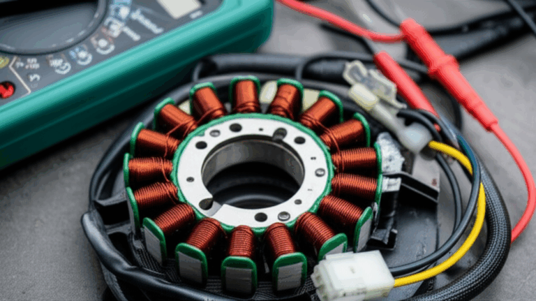
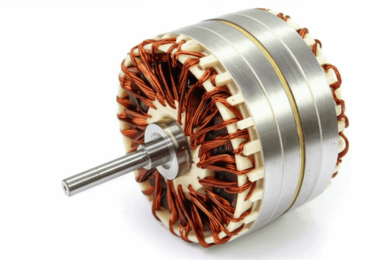
- Electric motor stator: Electromagnetic core built from laminated steel to reduce eddy currents.
If you want to read about laminated stator cores for motors or transformers these guides help. They don’t apply to torque converters directly. They do clarify what an electromagnetic stator looks like which prevents confusion.
- For a deep look at precision stator core lamination
- How manufacturers build and stack motor core laminations
- Materials that go into modern electrical steel laminations
Again this is a quick detour to clear terms. The torque converter’s stator does not use laminations. It uses fluid dynamics plus a one-way clutch.
FAQs I answer all the time
- Where exactly is the stator again?
It sits between the impeller and the turbine on a fixed stator support sleeve. The one-way clutch attaches it to that sleeve. The sleeve is part of the transmission pump which doesn’t spin with the engine.
- Can I see the stator without cutting open the converter?
Not really. The torque converter is a sealed unit inside the transmission bell housing. You can see the converter housing from outside. You can’t see the stator vanes unless the unit is cut open or disassembled during a rebuild.
- What happens if the stator were removed?
You’d lose torque multiplication. The converter would act like a simple fluid coupling. Launch performance would suffer and heat would likely rise under load.
- Is the stator touching the input shaft?
The turbine splines to the input shaft. The stator sits on its own support sleeve which is concentric with the input shaft. They share space but have different jobs and different supports.
- Is P0740 a stator code?
P0740 flags a torque converter clutch circuit malfunction. That’s a lock-up clutch control issue. A bad stator can still cause heat and shudder which confuses the diagnosis. I still treat P0740 as a TCC circuit problem first.
- Does the stator affect fuel economy?
Yes indirectly. If the stator won’t freewheel at cruise you get extra drag and heat. If it won’t lock at low speed you lose torque multiplication which forces the engine to rev more during launch. Both hurt MPG.
- Sprag clutch or roller clutch. Which is better?
Both work when built well. I care more about build quality and application. Performance and heavy duty units often use upgraded sprags or roller designs with better materials and heat treatment.
- How does the lock-up clutch play into this?
The lock-up clutch ties the impeller and turbine together during cruise. That reduces slip and heat which helps fuel economy. The stator keeps doing its thing in the background. It freewheels once coupling stabilizes.
- Can a stator cause noise?
Yes. A damaged sprag or roller clutch can chatter. Bent or broken vanes can cause rumble. Balancing issues can amplify vibrations.
- How long does a torque converter last?
Plenty run 100,000–150,000 miles or more. Many failures trace to the lock-up clutch or the stator’s one-way clutch. Heat and dirty ATF shorten life.
Quick maintenance and prevention tips
You can’t service the stator directly without opening the converter. You can help the system live a long life.
- Keep ATF fresh: Follow the fluid change interval for your vehicle. Severe duty means sooner. Clean ATF manages heat better and improves hydraulic function.
- Add cooling if you tow: A quality transmission cooler helps control ATF temperature on long grades and in hot climates.
- Fix lock-up issues quickly: A converter that never locks at cruise runs hotter. Heat kills the sprag clutch and the friction material.
- Use the right ATF: OEM-specified ATF matters. It sets the friction curve for the converter clutch and influences shear characteristics.
- Address small shudders early: Minor shudder can point to fluid breakdown or early clutch wear. Delaying the fix lets heat and debris cascade into bigger problems.
Bringing it all together: location and purpose in one tidy package
Here’s my short recap.
- Exact location: The stator sits between the impeller and the turbine on a fixed stator support sleeve that’s part of the transmission pump. A one-way clutch connects the stator to that support.
- Purpose: At low speed it locks and redirects fluid to multiply torque. At high speed it freewheels to avoid fighting the flow which protects fuel economy and shift quality.
- Symptoms when things go wrong: Overheating, sluggish launch, shudder, and reduced MPG. Sometimes a check engine light with related converter or TCC codes.
- Why you should care: The stator sets how your automatic transmission launches and how efficiently it cruises. It plays a massive role in heat generation, drivability, and fuel economy.
Once you know where the stator sits you understand why the torque converter works at all. It’s the middle blade pack with a one-way brain. It holds steady when you need a boost then it gets out of the way when you don’t. That’s elegant engineering inside a steel donut.
Extra technical notes for curious readers
I’ll leave you with a few finer points if you enjoy the details.
- Fluid dynamics: The converter operates as a hydrokinetic device. Kinetic energy transfers via controlled fluid motion between the impeller and turbine. The stator modifies that motion to improve energy transfer when the turbine lags the impeller.
- Heat generation: Fluid shear happens anytime impeller and turbine speeds differ. A stator that freewheels at cruise reduces shear. A stator that stays locked when it shouldn’t amplifies it. Heat load goes straight into ATF which affects seals, clutches, and electronics.
- Manufacturing and material properties: Stator vanes need strength to resist fluid forces and fatigue from cyclic loading. Good welds and tight tolerances keep vane shape consistent. Misbuilt stators can buzz or fail early.
- Converter balancing: Any imbalance shows up at highway speed as a vibration. The stator’s mass distribution contributes to balance along with the impeller, turbine, bearings, and thrust washers.
- System interactions: The torque converter lives inside the transmission bell housing. The transmission pump builds line pressure for the valve body and TCU-controlled solenoids. Those control lock-up clutch apply and release which changes heat and therefore stator stress.
If you want one more comparison point the “rotor” in electric machines sits opposite the stator. That’s a magnetic pairing not a fluid one. For a contrasting reference see how a rotor core lamination works in motors. It’s a different world with different goals which makes the torque converter’s hydrokinetic stator look even more unique.
You asked where the stator is. Now you know exactly where it sits and why that spot matters. If you’re chasing a drivability problem think heat, lock-up behavior, and launch feel first. The stator will tell on itself if you listen.