What Motor Does NASCAR Use? And What That Teaches Us About Motor Core Laminations
If you searched “what motor does NASCAR use,” you probably want a straight answer first. NASCAR Cup Series cars run a naturally aspirated, pushrod V8 with 358 cubic inches of displacement (about 5.86 L). These engines use electronic fuel injection, rev to around 9,000 RPM, and produce 670 hp on short tracks and road courses or 510 hp on superspeedways with a tapered spacer. They run on Sunoco E15 and come from builders like Roush Yates Engines (Ford), Hendrick Motorsports Engines (Chevrolet), and Toyota Racing Development (TRD).
Now let’s pivot to what most design engineers, product managers, and procurement teams actually need. If you’re designing electric motors or sourcing motor cores, the NASCAR question is a useful doorway. Why? It highlights how regulations, materials, manufacturing methods, and operating environments shape an engine’s architecture. Electric motors live by the same rules, just with a different physics playbook. Laminations sit at the heart of that playbook.
Below is a practical, engineer-to-engineer guide on motor core laminations. It follows a Problem – Explain – Guide – Empower framework. You’ll get the fundamentals, an unbiased look at options, and the steps to move forward with confidence.
In This Article
- Quick Answer: What Motor Does NASCAR Use?
- Why Lamination Material Choice Is Critical
- Understanding Core Losses: Eddy Currents and Hysteresis
- A Guide to Common Lamination Materials
- Key Manufacturing Processes and Their Impact
- Assembly Methods, Insulation, and Stacking Factor
- Which Application Is This For? Matching Materials and Processes
- Specifying for Procurement: Data, Tolerances, and Supplier Questions
- NASCAR Engines vs. Electric Motor Cores: A Brief Comparison
- Your Engineering Takeaway and Next Steps
Part 1: The Relatable Hook — Is This the Right Approach?
Every motor designer runs into the same fork in the road. You need higher efficiency and cooler operation, yet you have to hit a cost target and a delivery date. You’re weighing lamination thickness, material grade, coating class, tooling options, burr height, and bonding methods. You also have EMI limits, torque ripple targets, and noise caps to respect. It’s a lot.
If you’ve wondered whether you can meet those constraints without overpaying or hurting performance, you’re in the right place. Lamination material choice and manufacturing approach can make or break your design. Get them right early and you save iterative design cycles, dyno time, and field failures.
Part 2: What’s Really Going On? The Engineering Fundamentals
Let’s break the physics down to the essentials.
- Magnetic flux and permeability: Think of magnetic permeability as how easily a material allows magnetic field lines to pass through it. It’s like how a sponge soaks up water. Higher permeability generally helps you build more flux for a given magnetizing force.
- Core losses: When your motor runs, the alternating magnetic field in the stator and rotor core causes two main losses:
- Hysteresis loss: Energy lost because the material’s magnetic domains resist flipping direction every cycle. It depends on frequency and the material’s coercivity, which is its resistance to being demagnetized.
- Eddy current loss: The changing magnetic field induces small circulating currents inside the steel. These act like tiny electrical whirlpools and turn energy into heat. Eddy losses scale strongly with frequency and lamination thickness.
- Why laminations matter: Solid steel would behave like a giant shorted turn. Thin, insulated laminations break those eddy current loops into small pieces. Picture a river full of whirlpools. Now drop in a set of baffles. The whirlpools shrink and weaken. That’s what thin laminations and insulation coatings do for eddy currents.
- Lamination thickness: Thinner laminations cut eddy current losses at higher frequencies. You pay with higher material and manufacturing costs, possible handling difficulty, and sometimes more parts in the stack. Common thicknesses include 0.50 mm, 0.35 mm, 0.30 mm, and down to 0.20 mm or less for high-speed or high-frequency designs.
- Flux density and the B-H curve: The B-H curve tells you how the material magnetizes. Push too hard and you run into saturation. That drives up losses and heat. Materials with good permeability and low coercivity help you hit torque targets without cooking your core.
- Directionality: Grain-oriented steels shine along the rolling direction and underperform in other directions. Motors need multi-directional magnetization as the field rotates, so non-oriented electrical steel is the typical choice for rotating machines.
If you take nothing else from this section, take this: laminations reduce eddy losses, material choice controls hysteresis losses, and geometry plus process controls everything from torque ripple to heat to mechanical integrity.
Part 3: Your Options Explained — The Guide
You have two big levers to pull: material selection and manufacturing/assembly. Let’s walk them one by one.
Material Considerations
- Non-Oriented Electrical Steel (NOES, “M-grades” like M19, M27, etc.):
- Best for most motors since magnetic properties are similar in all directions.
- Thickness options cover a wide range and suit everything from industrial motors to BLDC and high-speed pumps.
- Pros: Balanced cost/performance, good availability, standardized specifications, well understood losses.
- Cons: Not as low-loss as cobalt-iron at extreme frequencies or flux densities.
- Silicon Steel Grades:
- Silicon increases electrical resistivity and reduces eddy current losses.
- Common in motor and transformer laminations. The shorthand “M19,” “M27,” etc. loosely relates to core loss categories and thickness classes defined by standards like ASTM A976, which classifies electrical steels by composition and magnetic properties.
- Pros: Proven, cost-effective, large material ecosystem.
- Cons: Performance trade-offs at high frequency or very high power density.
- Cobalt-Iron Alloys (e.g., 49% Co):
- High saturation flux density and strong mechanical strength at elevated temperatures.
- Pros: Outstanding power density and efficiency at high flux levels. Great for aerospace and compact, high-speed machines.
- Cons: Expensive and harder to source. You need tight process control.
- Nickel-Iron Alloys:
- Very high permeability at low flux densities.
- Pros: Useful for certain sensor or magnetic shielding applications and for low-loss core paths at low to moderate frequencies.
- Cons: Cost and availability can limit use in high-volume motors.
- Amorphous and Nanocrystalline:
- Extremely low core losses at high frequencies thanks to their microstructure.
- Pros: Excellent for transformers and certain specialized high-frequency motors.
- Cons: Brittle, thin ribbon forms, and challenging to stack into complex rotor or stator geometries at scale. Often more suitable for transformers or special topologies.
- Grain-Oriented Electrical Steel (GOES):
- Optimized for one direction of magnetization.
- Pros: The go-to for transformer cores where flux follows the grain.
- Cons: Poor fit for rotating machines since the field rotates and crosses the grain.
- Coatings and Insulations:
- Organic, inorganic, or mixed coatings create interlaminar insulation. They control interlaminar resistance, punchability, weldability, and thermal class.
- Choose coatings based on mechanical handling, bonding method, temperature rating, and dielectric performance.
Manufacturing & Assembly Processes
- Stamping (progressive die or stage tools):
- Best for high volume with consistent geometry and low piece cost once tooling is in place.
- Pros: High speed, controlled burr height, repeatability, and tight tolerances. Great for automotive and appliance volumes.
- Cons: Upfront tooling investment and lead time. Design changes after tool build create cost and delays.
- Laser Cutting:
- Ideal for prototyping and low to mid volumes. Handles intricate shapes.
- Pros: No tooling cost, fast iterations, and flexible geometries.
- Cons: Heat-affected zones can locally degrade magnetic properties if process control is poor. Edge quality and burr must be managed.
- Wire EDM:
- Ultra-precise but slow.
- Pros: Excellent edge quality and tight tolerances for complex or thick stacks.
- Cons: Cost and throughput limit it to prototypes or precision-critical parts.
- Waterjet:
- No heat-affected zone. Works on a wide range of materials.
- Pros: Useful for samples or thicker parts without thermal damage.
- Cons: Edge roughness and slower cycle time can be limiting factors.
- Skewing, Segmenting, and Stack Geometry:
- Skewed rotor or stator teeth can reduce cogging torque and torque ripple. Segmenting the stator can ease winding and improve slot fill.
- These design choices affect manufacturability, assembly complexity, and electromagnetic performance.
- Stack Assembly Methods:
- Interlocking: Tabs and slots form a mechanical joint between laminations. Think LEGO bricks. It’s fast and cost-effective with minimal heat impact.
- Bonding/Glue Laminations: Thin adhesive layers between lamellas create a rigid, quiet stack with excellent interlaminar insulation. Great for NVH and loss reduction.
- Welding: Spot or laser welds secure the stack. Control heat input so you don’t damage magnetic properties near the weld line.
- Riveting/Cleating: Mechanical retention without heat, though it adds hardware and possible stress concentrators.
- Impregnation: Varnish impregnation can stabilize the stack and improve vibration resistance.
- Insulation Management:
- Coating selection drives interlaminar resistance. High resistance reduces circulating currents across layers.
- Mind handling. Scratches or burrs can short laminations and raise core loss.
- Metrology and Testing:
- Measure stacking factor, burr height, flatness, and parallelism. Check dimensions at critical slots and bridges.
- Core loss testing can follow standards in the IEC 60404 series. Suppliers may report Epstein frame or single sheet tester data, along with permeability curves.
If you want the high-level rule of thumb: stamp when volume is high and geometry is stable. Laser or EDM when iterating or handling complex shapes at low volume. Choose interlocking or bonding when you need quiet, rigid stacks. Weld when you need strength and can manage heat input.
Part 4: Which Application Is This For? The Best-Fit Section
Every application tells a different story. Here’s how to map yours to materials and methods without bias.
- Industrial Induction Motors (50/60 Hz base speed with VFD operation):
- Material: NOES silicon steel, typically 0.35–0.50 mm.
- Manufacturing: Progressive die stamping for volume. Interlocking or bonding depending on NVH goals.
- Notes: Focus on efficiency standards, thermal performance, and cost per kW.
- BLDC and PMSM Drives (appliances, HVAC, pumps, robotics):
- Material: NOES silicon steel in 0.20–0.35 mm. Thin gauges reduce eddy losses at higher electrical frequencies.
- Manufacturing: Stamping for production, laser for prototypes. Bonding or interlocking to manage noise and stiffness. Pay attention to skew to reduce cogging.
- Notes: Torque ripple and acoustic performance matter. Keep an eye on magnet temperature and demagnetization.
- High-Speed Motors (turbomachinery, e-compressors):
- Material: Advanced NOES or cobalt-iron if you need high saturation flux density and strength.
- Manufacturing: Tight precision with laser or high-quality stamping. Bonded stacks for rigidity and balance. Strict burr limits.
- Notes: Rotor design dominates safety and performance. Validate burst speeds and rotor containment.
- Traction Motors (EV/HEV):
- Material: Thin-gauge NOES with low core loss. Some designers use advanced alloys in high-end designs.
- Manufacturing: High-volume stamping with fine-feature tools. Segmenting can boost slot fill and winding quality.
- Notes: Efficiency maps matter across a wide speed-load range. NVH is critical inside a cabin.
- Transformers vs. Motors:
- Transformers prefer grain-oriented steel and even amorphous ribbon for very low losses at line frequency. Rotating machines need NOES because the magnetic field rotates.
- Prototyping and Bridge-to-Production:
- Use laser or EDM to iterate quickly. Validate performance on a dynamometer or calorimetry rig. When geometry freezes, switch to stamping to cut unit cost.
Be honest with the limitations. Laser cutting offers exceptional flexibility for prototyping and low volume. Traditional stamping often delivers the best path to scale for simpler geometries and large runs. Bonding offers top-notch NVH and interlaminar resistance. Welding adds strength but needs careful thermal control. There is no single best method. There is only the best fit for your requirement matrix.
Part 5: Assembly Methods, Insulation, and Stacking Factor
You can hit your electromagnetic targets and still lose in the details. Watch these factors.
- Stacking Factor:
- It’s the ratio of steel height to total stack height. Coatings, adhesives, and air gaps reduce the factor. Lower stacking factor means less active material for the same stack height, which can trim torque or raise losses.
- Specify target stacking factor and measure it consistently.
- Burr Management:
- Burrs can short adjacent laminations and spike core loss. They also create assembly headaches.
- Set a burr height spec and audit it. Good tooling and maintenance pay off here.
- Insulation Class:
- Coating choice must match thermal class and process steps. Welding needs compatible coatings. So does bonding.
- Test interlaminar resistance and adhesion as part of incoming inspection.
- Skew and Cogging:
- Light skew reduces cogging torque and acoustic tones. It also spreads slot harmonics. You can skew laminations or skew windings depending on motor topology.
- Rotor Construction:
- Squirrel cage rotors need die casting and tight slot geometry. Interior permanent magnet rotors need bridges and precise magnet pockets. Surface PM rotors need accurate magnet retention and balance.
Part 6: Specifying for Procurement — Data, Tolerances, and Supplier Questions
When you write a lamination RFQ, clarity saves everyone time and money. Use this checklist.
- Drawings and 3D:
- Provide fully dimensioned drawings with GD&T. Call out critical-to-function dimensions. Include slot geometry, bridge thickness, and skew.
- Share a 3D model if you can. It reduces interpretation risk.
- Material Callouts:
- Specify grade, thickness, and coating class. Include target core loss at a defined flux density and frequency, and include the test method or standard (for example, IEC 60404 series). If you need a specific permeability or B-H curve, say so.
- Process Preferences:
- State if you require stamping or if laser is acceptable for prototypes. Note any restrictions on welding or bonding.
- Stack Assembly:
- Choose interlocking, bonding, welding, or a combination. Define stacking factor targets and any NVH requirements.
- Quality and Certifications:
- Ask for material certificates. Clarify ISO 9001 or IATF 16949 requirements for automotive work. Define PPAP levels if applicable.
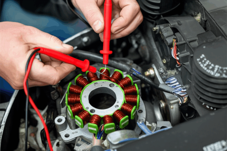
- Testing:
- Request core loss test data at your operating points. Ask for torque ripple or back EMF waveforms if the supplier does motor builds. For laminations, core loss and stacking factor are the essentials.
- Logistics:
- Define lot sizes, packaging to protect edges and coatings, and labeling. Agree on traceability and serialization schemes if needed.
- Commercial:
- Capture tooling cost, amortization options, and change management. Include lead times for both prototype and production.
A good supplier will welcome this level of specificity. It keeps surprises off the shop floor and out of your BOM.
Part 7: NASCAR Engines vs. Electric Motor Cores — A Brief Comparison
Let’s connect back to your original question and fold in key NASCAR terms without the fluff. The NASCAR Cup Series uses a naturally aspirated V8 engine with a pushrod valvetrain and electronic fuel injection. Displacement sits at 358 cubic inches. Horsepower targets depend on the rules package: 670 hp on short tracks and road courses and 510 hp on superspeedways when NASCAR mandates a tapered spacer. Peak RPM approaches 9,000. Torque lands around 530 lb-ft. The engines run Sunoco E15 fuel.
Chevrolet, Ford, and Toyota all supply engines through Hendrick Motorsports Engines, Roush Yates Engines, and Toyota Racing Development. NASCAR’s Next Gen car introduced a common chassis and a rear transaxle, yet the core engine architecture stayed consistent. NASCAR enforces parity with strict engine specifications and technical inspection. Teams validate performance with dyno testing. They watch engine cooling, lubrication, intake and exhaust design, and durability. They also manage engine rebuild intervals measured in hundreds of miles rather than thousands. Historically, restrictor plates limited power on superspeedways. The series now uses tapered spacers to achieve similar goals. You’ll still hear fans talk about the NASCAR engine sound and the engine noise at a race. That signature comes from a big-bore pushrod V8, high RPM, and open exhaust.
Why does this matter to an electric motor designer? Constraints shape architecture. NASCAR engine regulations limit displacement, valve train design, and airflow. Electric motor rules come from physics and materials science. Laminations limit eddy currents. Coatings maintain interlaminar insulation. Manufacturing controls burrs and fit. Both worlds balance performance, reliability, cost, and rules. Engineers in both spaces live by data and testing. Cup Series teams measure horsepower and RPM on the dyno. Motor teams measure core loss, back EMF, torque, and temperature rise. Both iterate and refine.
A quick list of NASCAR engine themes that mirror motor engineering tradeoffs:
- Engine specifications and rules control the design space. So do your lamination grade, thickness, and geometry limits.
- Suppliers matter. Hendrick, Roush Yates, and TRD deliver engines to teams under strict compliance. Your lamination partner must deliver tight tolerances, repeatable stacks, and accurate magnetic properties.
- Performance balancing exists everywhere. NASCAR uses tapered spacers for superspeedways. Motor designers use lamination thickness and material grade to balance efficiency and cost at the target frequency.
- Development never ends. NASCAR engine changes and testing mirror your design cycles and dyno sessions. You tune slot shapes and skew much like they tune camshafts and intake systems.
- Reliability is king. A blown engine ends a race. A shorted lamination stack or poor bonding torpedoes efficiency and life.
You may also see headlines about hybrid NASCAR engine rumors or even electric NASCAR engine speculation. The Cup Series remains pushrod V8 today. If hybrids arrive, laminated cores will move front and center. Motor laminations would then become part of the NASCAR conversation just like they are in every modern EV powertrain.
Part 8: Concrete Examples That Help You Decide
A few real-world scenarios can anchor the tradeoffs.
- Example 1: Appliance BLDC motor at 15–20 kHz electrical frequency
- Problem: The design needs to cut heat and noise while maintaining torque.
- Approach: Move from 0.35 mm to 0.27 mm NOES with a higher-resistivity coating. Switch from interlocking to bonding to stiffen the stator and lower audible buzz. Add a small skew to reduce cogging.
- Outcome: 10–15% core loss reduction in the target speed band with a measurable NVH improvement. Unit cost rises slightly yet total energy cost and warranty risk drop.
- Example 2: Industrial induction motor with VFD
- Problem: Efficiency must meet a regulatory class and hold under variable-speed operation.
- Approach: Keep 0.50 mm laminations for cost reasons but upgrade the grade to a lower-loss silicon steel. Work with the toolmaker to limit burr height and improve slot edge quality. Validate core loss with supplier data at the top two operating frequencies.
- Outcome: Meets efficiency target with minimal CapEx. Production stays on schedule.
- Example 3: High-speed compressor motor
- Problem: Rotor stress and core loss spike at high RPM. The unit runs hot.
- Approach: Consider a cobalt-iron stack for the stator to boost allowable flux and reduce tooth saturation. Move to bonded stacks for mechanical rigidity and better balance. Tighten tolerances on bridge thickness in an IPM rotor.
- Outcome: Higher power density at lower temperature rise. Cost per unit increases, which is acceptable for a premium product.
Part 9: Practical Internal Anatomy — Stator, Rotor, and System Integration
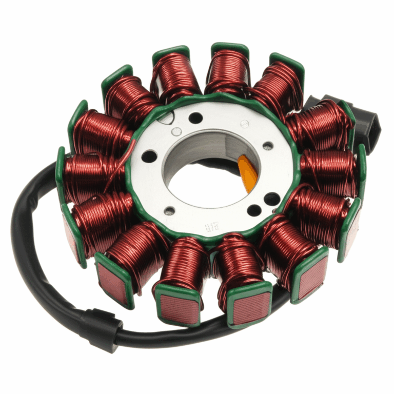
- Stator:
- The stator core lamination defines slot count and shape, tooth geometry, and back-iron thickness. It forms the magnetic return path and influences torque ripple and efficiency.
- Slot liners, wedge design, and impregnation affect thermal paths and partial discharge risk in high-voltage windings.
- Rotor:
- The rotor core lamination shapes magnet placement for PMSM or bar geometry for induction rotors. Bridges, ribs, and slit patterns trade mechanical integrity against leakage and saliency.
- Balance and containment are critical at speed. Validate with overspeed tests and FEA.
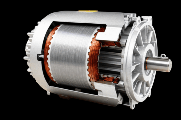
- System:
- The power electronics, cooling approach, and mechanical housing interact with the core’s losses and temperature. Lower core loss eases the cooling burden and can shrink heat sink size.
If you need a broader overview, this page on motor core laminations lays out how stator and rotor parts come together in a stack for different motor types. For upstream material insight, see electrical steel laminations.
Part 10: Common Pitfalls and How to Avoid Them
- Ambiguous specs:
- Don’t say “M19 equivalent” without defining thickness and core loss at a specific flux and frequency. Tie the requirement to a measurable standard and include the test method.
- Overlooking coating compatibility:
- A coating that is great for stamping may not bond well. A weld-friendly coating may not give you the interlaminar resistance you expect. Validate the stack’s actual performance, not just the sheet’s.
- Ignoring burrs and shorts:
- Burrs rise with dull tooling or aggressive feeds. They can short laminations and spike losses. Set a burr spec and audit it.
- Skipping early samples:
- You can’t spot all issues in simulation. Cut a laser or EDM prototype and run it. Check core loss, back EMF, and temperature rise before you commit to tools.
- Underestimating vibration:
- Bonding and impregnation can pay off in quieter operation. NVH problems are cheap to fix on the bench and expensive to fix in the field.
Part 11: Sourcing Confidence — Trust Signals and Standards
You build confidence with data and standards.
- Magnetic property tests:
- IEC 60404 series covers methods for measuring magnetic properties of electrical steels. Suppliers should reference it when reporting core loss and permeability.
- Loss separation approaches based on widely cited models in the literature, including the Bertotti framework, help you interpret frequency and flux trends without guesswork.
- Material classification:
- ASTM A976 provides a classification system for electrical steels by composition and magnetic properties. Use it to anchor your material callouts.
- Quality systems:
- ISO 9001 helps with general quality management. IATF 16949 applies in automotive supply chains.
- PPAP and control plans build traceability and repeatability into production.
- Documentation:
- Ask for B-H curves, core loss versus frequency, and coating type. Confirm thickness tolerance and flatness. Validate stacking factor on production stacks, not just coupons.
Part 12: Frequently Asked Engineer-to-Engineer Questions
- How thin is thin enough?
- If your electrical frequency is below a few hundred Hz, 0.35–0.50 mm may be fine. At several kHz and beyond, thinner gauges like 0.20–0.27 mm often make sense. The exact crossover depends on flux density and duty cycle.
- When do I choose cobalt-iron?
- When you need high saturation flux density or when mechanical strength and temperature performance justify the cost. Aerospace and compact high-speed motors are typical use cases.
- Does welding ruin my stack?
- Not if you control heat input and location. Keep welds away from the most flux-dense regions or use shorter spots. Validate losses on welded coupons.
- Is bonding worth it?
- If you care about NVH and interlaminar resistance, bonding pays off. It can raise material cost and add process steps. You decide based on lifecycle value.
- How do I validate supplier data?
- Request test conditions, standards used, and raw curves. Re-test in-house or at a third party when the program is critical.
Part 13: NASCAR Engine Specs — The Quick Reference You Asked For
Here’s a concise snapshot that captures common NASCAR engine search terms and answers many of the questions people ask.
- Engine type and configuration:
- Naturally aspirated V8 with an overhead valve (OHV) pushrod design. Internal combustion, not turbocharged or supercharged.
- Displacement:
- 358 cubic inches or about 5.86 liters.
- Fuel system and fuel:
- Electronic fuel injection. Sunoco E15, a 15% ethanol blend.
- Horsepower and RPM:
- About 670 hp on short tracks and road courses. About 510 hp at Daytona and Talladega with a tapered spacer. Peak RPM near 9,000.
- Torque:
- Roughly 530 lb-ft with strong mid-range pull.
- Engine suppliers:
- Chevrolet via Hendrick Motorsports Engines. Ford via Roush Yates Engines. Toyota via Toyota Racing Development.
- Next Gen context:
- The Next Gen car introduced in 2022 uses a common chassis and a rear transaxle. The core V8 engine architecture remains similar with strict engine regulations.
- Rules and parity:
- NASCAR enforces engine specifications, conducts technical inspection, and uses dynamometer testing to verify compliance. Engines run different rules packages by track type.
- Superspeedway control:
- Historically restrictor plates. Now tapered spacers limit airflow and manage speeds at Daytona and Talladega.
- Reliability and rebuilds:
- Engines face extreme duty cycles, which is why teams rebuild frequently. They measure lifespan in race distances, not road-car miles.
- Sound and spectacle:
- The pushrod V8 exhaust note is a signature piece of the show. Fans notice engine sound immediately.
- Evolution and future:
- NASCAR engine technology evolves within tight constraints. Hybrid NASCAR engine rumors and electric NASCAR engine speculation appear in the news periodically. The series continues to run pushrod V8s today.
- Comparisons:
- NASCAR engine vs F1 engine and NASCAR engine vs IndyCar engine show very different choices. F1 runs a 1.6 L V6 turbo-hybrid. IndyCar uses turbocharged V6s. NASCAR sticks with a large displacement V8 and a different philosophy on parity and spectacle.
You can call those “NASCAR engine specifications,” “NASCAR engine rules,” “engine output,” “engine performance,” “engine durability,” and so on. The exact terminology varies, yet the facts hold steady. NASCAR tunes horsepower and airflow to track type. Teams optimize within the box, and the series polices the box with inspection and dyno testing.
Your Engineering Takeaway — The Empowering Conclusion
Let’s close with a crisp summary you can act on.
- Laminations control core loss and heat. Thinner, well-insulated laminations reduce eddy currents at higher frequencies.
- Material choice drives hysteresis loss and saturation. NOES silicon steels fit most motors. Cobalt-iron and other advanced alloys serve high-power-density or high-speed designs.
- Manufacturing sets the cost and tolerance stage. Stamp for volume. Laser or EDM for flexibility. Control burrs and edges.
- Assembly methods matter. Interlock for speed. Bond for NVH and insulation. Weld for strength with managed heat.
- Specify like a pro. Tie core loss, thickness, and B-H to recognized standards. Define coating class, stacking factor, and burr limits. Include test methods.
- Validate with data. Ask for curves and test points that match your operating conditions. Build and test early samples.
Action steps you can take this week:
- Define your operating frequency range and target flux density. That gives you a first-pass lamination thickness and material grade.
- Draft a one-page lamination spec that includes grade, thickness, coating class, target core loss and test method, stacking factor, and burr limit.
- Choose your prototype path. If you plan to iterate geometry, start with laser cut stacks. If your design is stable and volumes justify it, open a stamping tool.
- Line up testing. Confirm core loss at your frequency and flux. Check back EMF and torque ripple against your NVH goals.
- Shortlist suppliers. Look for those with ISO or IATF credentials, real test reporting, and a clean track record on burrs, flatness, and stacking factor.
When you’re ready to go deeper on specific subassemblies, review the fundamentals behind motor core laminations and how the stator core lamination interfaces with the rotor core lamination. For upstream material context, this overview of electrical steel laminations is a good primer.
References and standards to consult:
- IEC 60404 series on magnetic materials testing and characterization.
- ASTM A976, classification of electrical steels by composition and magnetic properties.
- IEEE Transactions on Magnetics and related conference proceedings for loss modeling and material behavior.
- G. Bertotti, Hysteresis in Magnetism, for loss separation concepts.
You asked about NASCAR engines. You now have that answer. More importantly, you have a clear path to specify and source the laminations that will make your next motor run cooler, quieter, and more efficiently.