What Is the Hellcat Motor? A Straight Answer, Then the Engineering Guide You Came For: Motor Laminations 101
You searched “what is the Hellcat motor” which usually points to one thing. Dodge’s famous supercharged 6.2-liter HEMI V8. I’ll answer that in one minute. Then I’ll pivot to the motor topic many engineers, product designers, and procurement managers actually need when they land on pages like this. How lamination material and manufacturing choices drive electric motor performance, cost, and reliability.
If you build or buy electric machines, stay with me. You’ll walk away with a clear mental model for core losses, a calm framework for material and process selection, and a short list of practical next steps to de-risk your bill of materials.
Quick answer: the Hellcat “motor” in plain English
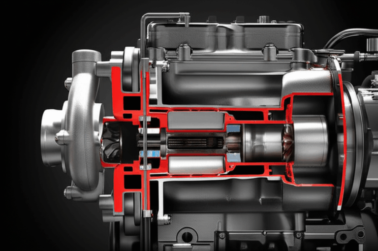
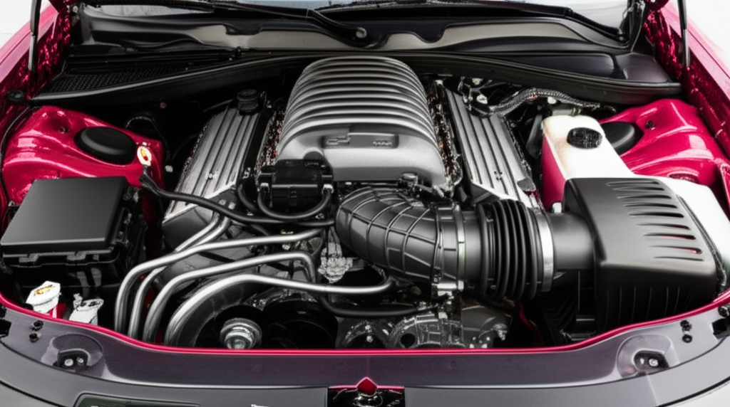
Dodge’s Hellcat engine is a 6.2-liter (370 cu in) supercharged HEMI V8 developed by SRT. It uses a twin-screw IHI supercharger that displaces 2.4 liters in standard Hellcat cars and 2.7 liters in higher output variants. The standard SRT Hellcat makes roughly 707 to 717 horsepower with 650 lb-ft of torque. Factory boost sits near 11.6 psi for the standard tune. The Hellcat Redeye bumps boost and airflow which yields 797 to 807 horsepower. The limited-production Demon went further with fuel and drag-strip calibration which delivered 808 horsepower on premium pump gas and up to 840 horsepower on high octane race fuel. Jeep’s Grand Cherokee Trackhawk uses the 707 horsepower version. Ram’s 1500 TRX gets about 702 horsepower. Dodge’s Durango SRT Hellcat sits near 710 horsepower. Most production models pair to ZF’s 8-speed automatic. A Tremec manual appeared in some Challenger Hellcat years.
Why the fuss? Immense output from a factory car, a distinct supercharger whine, and durable forged internals. It wrote a loud chapter in American muscle. Now let’s talk about motors in the electrical sense because that is where laminations enter the picture.
In This Article
- Why Lamination Material Choice Is Critical
- Understanding Core Losses: Eddy Currents and Hysteresis
- A Guide to Common Lamination Materials
- Manufacturing and Assembly Processes That Matter
- Matching the Right Approach to Your Application
- Quality, Standards, and Validation
- Cost Levers for Procurement
- Rules of Thumb and Quick Checks
- Your Engineering Takeaway
Why Lamination Material Choice Is Critical
Here’s the actual engineering problem on the table. You need higher efficiency and power density without watching your BOM costs run away. You also want lower temperatures, quieter operation, and stable supply. The motor core sits at the center of that trade space. The thickness, grade, insulation, and assembly of your laminations shape magnetic losses which drive heat and efficiency. They also set the mechanical backbone for the rotor and stator. Get them right and you unlock better torque per amp with less waste heat. Miss by a little and you build thermal overhead into the design that you can never tune out later.
Two questions usually start the conversation:
- How does lamination thickness affect losses at my electrical frequency and flux levels?
- Which steel grade and insulation fit my speed, temperature, and cost targets?
You do not need a graduate course in magnetics to answer those. You need to understand two loss mechanisms, a few material families, and how manufacturing touches magnetic properties.
Understanding Core Losses: Eddy Currents and Hysteresis
Let’s translate the physics into practical terms.
- Eddy currents: Picture a river with swirling eddies behind a rock. Changing magnetic fields induce circular electrical currents inside a solid steel core which creates heat. Thinner laminations break big “whirlpools” into small ones which reduces loss. Insulation between laminations blocks current from looping across the stack.
- Hysteresis: Magnetic domains inside the steel flip direction each AC cycle. That flip has a friction-like cost. Materials with lower coercivity, which is the resistance to switching magnetization, reduce this loss.
Both losses scale with frequency and flux density. Eddy current loss rises roughly with the square of lamination thickness and the square of frequency. Hysteresis scales roughly linearly with frequency and with a power of flux density that sits a bit above 1 in many steels. That is why high-speed machines rarely use thick laminations and why designers watch flux swing carefully on the B-H curve.
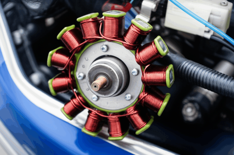
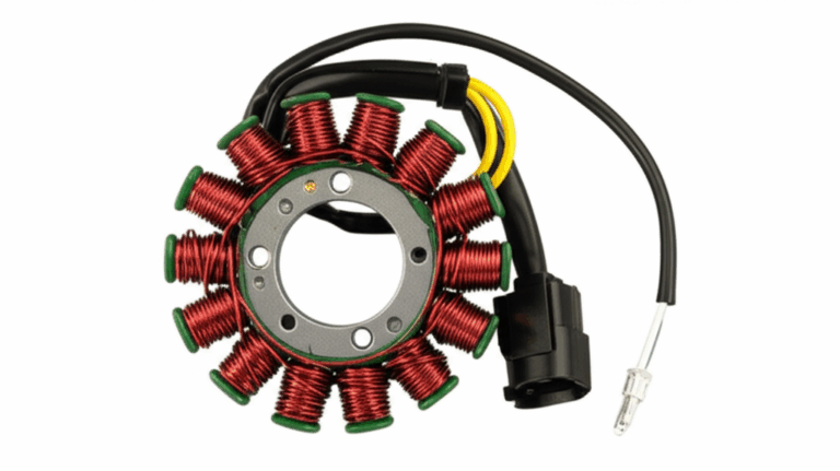
The anatomy of a motor core
- Stator: Laminated teeth and yoke that carry the bulk of the magnetic flux. Winding turns set magnetomotive force and copper loss. The lamination steel sets the magnetic “pipe size” for the flux.
- Rotor: Laminated core with a squirrel-cage in induction machines or buried or surface-mounted magnets in PM motors. The rotor sees high centrifugal loads at speed which means the stack must deliver mechanical integrity without killing magnetic performance.
You want high permeability, low loss, and robust mechanical behavior. You balance those with manufacturability and cost.
Insulation coatings and stacking factor
Each lamination has a thin inorganic or organic coating that adds electrical resistance between layers. That coating reduces eddy currents yet it also reduces “stacking factor,” which is the iron fraction in a stack. Higher coating thickness lowers stacking factor which increases the overall stack height for a target magnetic path length. You tune that balance by frequency, thermal class, and bonding method. Industry uses coating classes defined by standards. The exact class code matters less than understanding temperature rating, interlaminar resistance, and weldability or bondability.
Temperature matters
Loss becomes heat. Heat changes resistivity and magnetic properties. Coatings and adhesives have temperature limits. Mechanical properties shift with heat. Your lamination selection lives inside the motor’s thermal story which includes slot fill, cooling scheme, and duty cycle.
A Guide to Common Lamination Materials
You have four main buckets when you think about electric machines for mobility, industrial drives, appliances, and aerospace. Non-oriented electrical steels, grain-oriented electrical steels, cobalt-iron alloys, and amorphous metals. Each brings a different trade profile.
Non-oriented electrical steel (NOES)
- Use cases: Most rotating machines like induction motors, BLDC, IPM, and SRM across 50 to 400 Hz electrical frequency and up through several kilohertz in specialized designs with thin gauges.
- Why it works: Magnetic properties are near-isotropic in-plane which suits rotating flux paths. Silicon content usually sits near two to three percent which lowers loss and raises resistivity.
- Gauges: Common thicknesses include 0.50 mm, 0.35 mm, 0.30 mm, 0.27 mm, and 0.20 mm with thinner gauges aimed at higher frequency or higher speed machines. Thinner means lower eddy current loss with a cost increase and higher manufacturing difficulty.
- Tradeoffs: As gauge drops, material and processing costs rise. Burr control gets harder. Mechanical stiffness drops which can raise vibration risk if you do not tune stack compression and bonding.
If you want a quick primer on products and forms, scan this overview of electrical steel laminations. It will help you align terminology with your supplier’s quoting language.
Grain-oriented electrical steel (GOES)
- Use cases: Transformers and static magnetic circuits where flux stays along one direction. Rarely used in rotating machines.
- Why it works: Rolling and annealing create a preferred crystal orientation that gives very low loss along the rolling direction.
- Tradeoffs: Great for transformers which live at mains frequency with near-unidirectional flux. Not a fit for rotating machines because off-axis properties degrade.
Cobalt-iron alloys
- Use cases: High power density and high frequency machines like aerospace actuators, high-speed spindles, or compact traction motors where flux density needs to run high.
- Why it works: Higher saturation flux density than silicon steel. That allows greater torque per core cross-section at the same flux density or the same torque at lower flux density which can cut losses.
- Tradeoffs: Material costs climb fast. Machining and stamping get tougher. You need to control heat treatment tightly.
Amorphous and nanocrystalline metals
- Use cases: High-frequency transformers and specialized machines with very low loss needs in the tens of kilohertz and beyond.
- Why it works: Lack of crystalline structure reduces hysteresis loss significantly.
- Tradeoffs: Brittle strips bring handling challenges. Geometries get constrained.
What about coating types
Common electrical steel coatings provide a mix of insulation resistance, weldability, and thermal endurance. You will see thin inorganic coatings that tolerate welding or bonding. You will see “backlack” adhesive coatings that deliver strong interlaminar bonds after baking. The right choice depends on your process route and thermal class. Industry standards categorize coatings by functional properties so ask your supplier for the class designation and test data for interlaminar resistance and temperature rating.
If you need a quick refresher on shapes, stack types, and how they relate to quotes and MOQ, this concise page on motor core laminations will help you align vocabulary across teams.
Manufacturing and Assembly Processes That Matter
Material selection sets the ceiling for performance. Manufacturing decides how close you fly to it.
Cutting methods
- Progressive die stamping: Ideal for high-volume production with stable geometry. Tooling cost is higher up front. Per-part cost falls hard with volume. You get high repeatability with good burr control when dies are sharp and setups stay tuned.
- Compound and fineblanking: Useful for tighter tolerances or thicker sections where edge quality matters.
- Laser cutting: Great for prototyping and low volume. Complex geometries are easy. Watch the heat-affected zone which can raise local losses. Post-cut stress relief anneal can recover properties at a cost.
- Wire EDM and waterjet: Niche methods for extreme precision or special alloys. Slow and costly which fits development or very low volume.
Pick by volume, tolerance, and loss sensitivity. If you plan to move from laser-cut prototypes to stamped production, build a validation step into your program because magnetic losses can shift when you change cutting methods.
Burrs, edge quality, and stress
Burr height and recast layer thickness affect stacking factor, slot fit, and interlaminar shorting risk. Mechanical shearing and thermal cutting induce stress at the edge which raises local hysteresis loss. You can mitigate with sharp tooling, proper clearances, and annealing if the material and coating allow it. Do not skip burr measurement and edge microstructure checks in PPAP for safety critical designs.
Stacking and joining
- Interlocking: Tabs and slots snap laminations together like LEGO bricks. You get a rigid stack with no weld heat. You need to control tab geometry to avoid local stress risers and magnetic leakage.
- Welding: Spot or laser welds deliver strength and speed. They bring local heat that can degrade magnetic properties if not controlled. Use minimal energy and well-placed welds. Validate losses.
- Adhesive bonding: Backlack or applied adhesives provide excellent damping and uniform stack compression. You need bake cycles and clean handling. It performs well thermally if the adhesive fits your class rating.
- Cleats and rivets: Simple and robust. They add local material and can disturb flux if you place them poorly.
Your method sets vibration behavior, noise, and thermal pathways. High-speed rotors benefit from uniform bonding which spreads stress and increases damping. Stators in appliances can use interlocks to lower cost without big acoustic penalties.
Insulation and slot liners
Coatings on laminations control interlaminar resistance. Slot liners and phase separators manage voltage withstand and thermal class. They also influence slot fill and thermal transfer. Early coordination between the lamination team and the winding team pays off because a millimeter wasted in the slot is a millimeter you never get back.
For stator and rotor stack discussions, it can help to ground the conversation with shared references. See stator core lamination for typical forms and constraints. Compare that with rotor core lamination to see how geometry and assembly choices diverge when centrifugal loads enter the picture.
Matching the Right Approach to Your Application
Every application carries its own constraints. Use this section as a sanity check before you lock decisions.
Industrial induction motors (IE3 to IE5 goals)
- Frequency: 50 or 60 Hz fundamental with harmonic content from PWM drives.
- Typical gauges: 0.50 mm down to 0.35 mm for cost-sensitive designs. 0.30 mm or 0.27 mm when premium efficiency targets justify it.
- Material: Non-oriented silicon steel with loss classes that meet your efficiency goal. Focus on low-loss grades with good punchability.
- Joining: Interlock for cost or bonding for noise reduction. Welding stays limited to select cases due to local loss rises.
Why: You chase low total cost of ownership and broad availability. Thinner gauges cut eddy losses but watch cost and slot fill.
BLDC and IPM motors for appliances and e-bikes
- Frequency: Electrical frequency can reach several hundred Hertz under speed. PWM adds high-frequency ripple.
- Gauges: 0.35 mm to 0.27 mm as a baseline. 0.20 mm if noise and efficiency demand it.
- Material: Non-oriented steel with coatings that support adhesive bonding or interlocking. Low loss at higher frequency matters.
- Joining: Bonding helps acoustics and reduces buzz. It also stiffens thin stacks.
Why: Users feel noise and efficiency in daily use. Small gains matter.
Traction motors for EVs and hybrids
- Frequency: Depends on pole count and speed. High-speed designs push into kilohertz ripple zones on the switching side.
- Gauges: 0.27 mm and 0.20 mm in many high-performance designs.
- Material: High-grade NOES or cobalt-iron when you need more headroom in saturation. Validate with inverter spectrum and thermal model.
- Joining: Bonded stacks for both rotor and stator. Tight control of concentricity and dynamic balance.
Why: You need high power density and repeatable thermal behavior under fast transients.
High-speed spindles and aerospace actuators
- Frequency: High fundamental or high ripple makes eddy losses the main enemy.
- Gauges: 0.20 mm and below for extreme cases if supply chain supports it.
- Material: Cobalt-iron for saturation margin. Validate cost and supply risk early.
- Joining: Bonding with high temperature adhesives. Precision machining and balancing become critical.
Why: The mechanical envelope is tight and the stakes are high.
Switched reluctance motors (SRM)
- Frequency: Often high with significant harmonic content due to the nature of excitation.
- Gauges: 0.35 mm to 0.27 mm. Some cases go thinner to control acoustic noise and loss.
- Material: NOES with attention to lamination edge quality because local saturation near salient poles drives hysteresis loss.
- Joining: Bonding helps noise and stiffness.
Why: SRMs trade magnets for control complexity so the steel carries more of the performance burden.
Transformers and chokes
- Frequency: 50 to 60 Hz for mains or much higher for power electronics magnetics.
- Material: GOES for mains transformers. Amorphous or nanocrystalline for high frequency.
- Form factors: EI and UI cores, toroids, and custom stacks. Coatings and anneal schedules drive loss.
Why: Flux stays directional which turns GOES into the efficiency winner at low frequency.
Quality, Standards, and Validation
You want vendors who certify material properties and who can correlate process settings to magnetic performance. Here are the standards and tests that show up most often.
- Material standards: EN 10106 covers fully processed non-oriented electrical steel. EN 10107 covers grain-oriented electrical steel. These are widely used in Europe and many suppliers align to them.
- Coatings: ASTM A976 classifies insulation coatings on electrical steels by properties like insulation resistance and thermal endurance.
- Magnetic testing: IEC 60404 is a family of standards for magnetic materials. The Epstein frame method and single sheet tester are common for loss and B-H curve measurement. Ask for the method used on your certificates.
- Motor efficiency: IEEE Std 112 describes methods for testing polyphase induction motors. Use it to align lab tests during validation.
- Automotive quality: PPAP and APQP practices apply when your motor ships into vehicles. Include stacking factor, burr height, and interlaminar resistance in your control plan. Tie them to loss targets.
Validate early. Prototype with the same gauge and a cutting method that does not mask losses. If you must laser-cut proto parts for speed, plan a stamped pilot run before you freeze performance targets.
Cost Levers for Procurement
Cost lives in the details. You can cut total cost without touching performance if you watch these levers.
- Strip width and nesting: Work with your supplier to match lamination OD to common coil widths. Better nesting raises yield and lowers cost.
- Gauge availability: Some gauges are abundant which shortens lead times and reduces price volatility. Check alternates early.
- Tooling strategy: If your forecast has a long tail at low volume, design your die to cover two or three sizes with shared stations. Modular tooling pays back.
- Coating choice: Backlack or high-grade coatings raise material cost yet they may cut assembly time or weld operations. Price the system not the sheet.
- Anneal options: Stress relief anneal can recover losses for laser-cut parts. It adds cost so use it strategically.
- MOQ and supply risk: Premium grades and ultra-thin gauges can carry long lead times. Qualify a second grade that meets your floor for performance in case allocation hits.
A calm negotiation starts with a shared drawing set that includes gauge, coating class, burr limits, stacking factor targets, and joining method. Ambiguity costs money.
Rules of Thumb and Quick Checks
Use these as a first-pass filter. Then run the detailed numbers with your team.
- Eddy current loss scales with the square of lamination thickness and roughly the square of frequency at constant flux swing. Drop gauge from 0.35 mm to 0.27 mm and you can expect eddy loss to fall by about 40 percent if all else stays equal.
- Hysteresis loss scales roughly linearly with frequency for a given material and flux swing. If your duty cycle includes high-frequency PWM ripple, select materials tested with single sheet methods at those frequencies.
- Electrical frequency equals mechanical speed times pole pairs. A 10-pole machine at 6,000 rpm sees 500 Hz fundamental. Use that to pick gauge and loss class.
- Stacking factor drives torque density. If you move to a thicker coating to enable bonding, adjust stack height to recover iron cross-section and recheck mechanical envelope.
- Bonded stacks damp vibration better than interlocked stacks. If acoustics matter, try bonding before you throw exotic materials at the problem.
- If you switch from laser-cut to stamped parts, test core losses at the same flux density and frequency because cutting method matters.
The honest truth about “best”
Engineers often ask for the “best lamination.” There is no universal champ. There is the best fit for your blend of frequency, flux density, thermal class, speed, noise targets, quantity, and cost. High cobalt content looks heroic on a datasheet yet a high-grade non-oriented silicon steel may deliver the same system efficiency when you factor in inverter switching, copper loss, and cooling options. Start with the system. Land on the stack.
A short clarification on naming
In automotive circles “motor” sometimes means internal combustion engine. In power electronics and electrification “motor” means an electric machine. The Hellcat engine is an ICE and does not use lamination stacks in the way electric motors do. That is why we separated the quick Hellcat answer from the in-depth lamination guide. If your team is working on traction motors for vehicles that once carried Hellcat badges, the lamination guidance above applies directly.
Your Engineering Takeaway
- Lamination decisions drive efficiency, temperature, noise, and cost. You can change the story by picking the right gauge, steel, coating, and joining method.
- Focus on the two core losses you can control. Eddy currents hate thick laminations at high frequency. Hysteresis hates materials with high coercivity and sloppy cutting.
- Choose material by application. NOES suits most rotating machines. GOES fits transformers. Cobalt-iron saves you when saturation headroom limits torque density at the cost of dollars and complexity.
- Match the manufacturing method to volume and sensitivity. Stamping wins on volume and repeatability. Laser cuts are fast for protos yet can inflate loss without anneal.
- Validate with the right tests. Align on standards and test methods. Measure losses at your operating flux density and frequency with the same cutting route you plan for production.
- Control cost with yield, shared tooling, and smart coating choices. Price the entire system not a single sheet.
If you need a quick shared reference during internal reviews, keep these on hand:
- Overview of electrical steel laminations
- Product forms for motor core laminations
- Geometry and assembly considerations for stator core lamination
- Rotor-specific constraints and options for rotor core lamination
Consider these your starting points. Share them with your supplier and use the same vocabulary. That alone cuts quoting cycles.
Actionable next steps
1) Define the operating electrical frequency range including PWM ripple. Convert from rpm and pole count where needed.
2) Set a flux density target in the teeth and yoke that meets torque without pushing saturation.
3) Select two candidate gauges that bracket your loss and cost targets. Get supplier data for those grades at your frequency.
4) Pick a manufacturing path for prototypes that mimics production where possible. If not, plan a stamped pilot before design freeze.
5) Lock a joining method that fits your acoustic and thermal goals. Bonding often pays back in high-speed or noise-sensitive machines.
6) Build the control plan with burr limits, stacking factor checks, and interlaminar resistance tests tied to loss targets.
7) Run cost scenarios with alternate gauges and coating types. Look for system-level savings like shorter bake cycles or reduced machining.
Engineers do not need sales pitches. You need clean data, predictable processes, and partners who speak your language. Use this guide to frame the conversation and make your next lamination decision with confidence.
References and further reading
- IEC 60404 series, Magnetic materials. Test methods for magnetic properties of electrical steel sheets.
- EN 10106, Non-oriented electrical steel sheet and strip delivered fully processed.
- EN 10107, Grain-oriented electrical steel sheet and strip delivered fully processed.
- ASTM A976, Standard Classification of Insulating Coatings by Composition, Relative Insulating Ability, and Application.
- IEEE Std 112, Standard Test Procedure for Polyphase Induction Motors and Generators.
- G. Bertotti, Hysteresis in Magnetism. Academic Press.
- IEEE Transactions on Magnetics. Various papers on core loss modeling and measurement.
Self-check of internal links:
- electrical steel laminations: used once
- motor core laminations: used once
- stator core lamination: used once
- rotor core lamination: used once
Total internal links used: 4. No duplicates.