What is the Function of Stator and Rotor? Unraveling the Core of Electric Machines
Table of Contents
- What is the Function of Stator and Rotor? Unraveling the Core of Electric Machines
- Why this topic matters right now
- What is a stator?
- What is a rotor?
- How do stator and rotor work together?
- How do motors and generators use stators and rotors?
- What kinds of stators and rotors are there?
- Why does the air gap matter so much?
- What losses cut efficiency and how do we fix them?
- How do we cool the stator and rotor?
- Where do we see stators and rotors in daily life?
- What problems cause failure and how do we prevent them?
- What design choices drive cost and power density?
- What materials matter in cores, windings, and frames?
- Quick buyer’s guide: How to pick the right machine
- Optional FAQ
- Summary: Key points to remember
- References
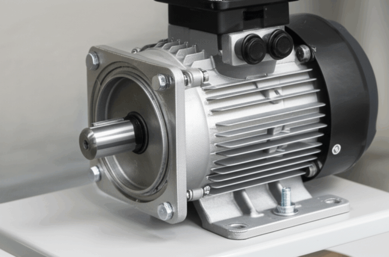
In every electric motor and electric generator you will find two core parts. The stator stays still. The rotor spins on a shaft. Together they turn electrical energy into mechanical energy or do the reverse. You see them in pumps, fans, HVAC systems, electric vehicles, and industrial machinery. Learn how they work. See why design choices matter. Make smarter picks for your projects.
I have spent years explaining complex gear in simple words. I will do that here. I will also show you where many teams stumble. Then I will share how you can fix it fast with the right parts, better design, and smart checks.
Problem: Motors waste power and fail too soon. Agitate: Heat, noise, and poor efficiency drive up cost and downtime. Solution: Understand the function of stator and rotor, pick better cores and windings, and tune the air gap, cooling, and controls.
Why this topic matters right now
Modern life runs on motors and generators. We pump water. We move air. We move people. We make power. The workhorse inside is simple in idea yet tricky in detail. If you get the stator and rotor function right you boost power density and life. You cut losses. You save money.
This article gives you clear answers in plain words. You will see how electromagnetism and magnetic flux density create torque and rotation. You will learn how different types like induction motor, synchronous motor, DC motor, and BLDC motor change the roles. You will also see simple tips you can use today.
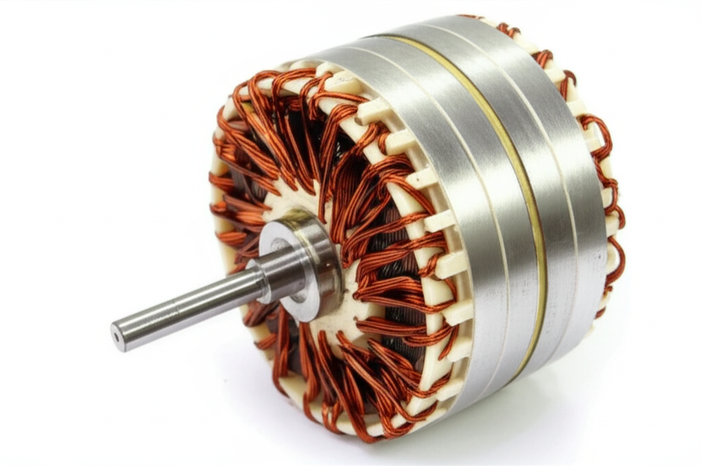
What is a stator?
A stator is the fixed part of a motor or generator. It holds a laminated core, windings, and a frame. The core is made from thin sheets to block eddy currents and cut hysteresis loss. We often use silicon steel for the core. We wind the slots with copper or aluminum. The frame gives structural support and helps heat dissipation.
The primary functions of the stator are simple. It makes the magnetic field that the rotor uses to make torque in a motor. Or it holds the armature windings that pick up voltage generation in a generator. In AC machines, the stator often creates a rotating magnetic field with three-phase power. In DC machines and some synchronous generators, the stator can carry the main power windings while the rotor carries the field winding.
If you design or buy stators you will care about the stator windings role, insulation classes, cooling system for stator, and magnetic poles in stator. You will also care about the quality of the stator core lamination because it shapes losses, noise, and life.
What is a rotor?
A rotor is the part that turns. It has a laminated core, windings or bars, a shaft, bearings, and often a fan. Some rotors include a commutator or slip rings. In motors the rotor interacts with the stator field to produce torque. In generators the rotor cuts flux in the stator to create EMF and current.
The primary functions of the rotor are to:
- Produce mechanical rotation and torque in a motor
- Generate electrical current in a generator by cutting flux
- Carry the armature or the field winding based on the machine type
The mechanical integrity of the rotor matters. So does rotor balancing importance. The rotor sees mechanical stress, thermal stress, and high RPM swings. A good rotor core lamination cuts losses and noise. It also helps the cooling system for rotor do its job.
How do stator and rotor work together?
Two laws explain it. Faraday’s Law of Induction says a changing flux makes voltage in a loop. Lorentz Force says a current in a magnetic field feels a force. Put them together and you get motion or power.
In a motor the stator makes a field. The rotor sees a change in flux linkages. This induces current flow in windings or bars. That current in the rotor meets flux from the stator and feels a force. That force makes torque. The shaft turns. You get mechanical energy at the rotor shaft. That is the principle of operation electric motor.
In a generator the shaft spins the rotor. The rotor’s field sweeps across the stator armature winding. The changing flux makes voltage generation in coil by Faraday’s law. You get electrical energy at the stator. That is how electric generator action works.
How do motors and generators use stators and rotors?
- Induction motors: The induction motor stator makes a rotating field with three-phase power or single-phase power. The induction motor rotor gets induced current. This creates torque. The speed lags the stator field. We call that lag slip in induction motors.
- Synchronous motors and generators: The stator often holds the armature. The rotor holds the field winding or permanent magnet. The rotor locks to the field at synchronous speed. That makes tight control and high power factor improvement stator possible with the right setup.
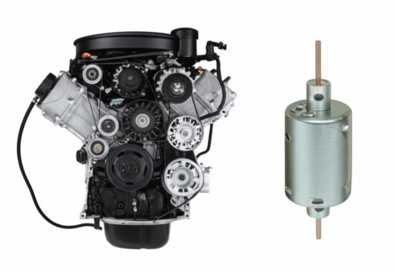
- DC motors: The stator gives a stationary magnetic field using permanent magnets or a field winding. The rotor is the armature and gets current through a commutator. This commutator role DC motor switches current to keep torque in one direction.
- Brushless DC (BLDC) motors: The stator has the windings. The rotor has permanent magnets. Electronic commutation replaces brushes. This gives high motor efficiency stator rotor and low maintenance. For BLDC builds the right bldc stator core helps reduce core losses reduction and noise.
What kinds of stators and rotors are there?
- Types of stators: A wound stator uses coils in slots. A permanent magnet stator uses magnets to set the field. Each has pros and cons. The advantages of wound stator include easy control and no rare earth cost. PM stators can give high power density with simple control in BLDC drives.
- Types of rotors:
- Squirrel cage rotor: Simple bars and end rings. Tough and cheap. Easy to cool. This is common in induction motors. The advantages of squirrel cage rotor include high reliability and low cost.
- Wound rotor: Coils on the rotor with slip rings. You can add external resistance to control starting torque and speed. This wound rotor operation offers soft starts.
- Salient pole rotor: Poles stick out. Used in low to medium speed synchronous machines. Good for generator excitation system and large hydro units.
- Cylindrical rotor: Smooth rotor for high speed synchronous generators like gas or steam turbines.
- Permanent magnet rotor: Used in BLDC and PM synchronous motors. High power density and efficiency.
You also see special forms like linear motor components with a linear stator and rotor. Linear motor stator rotor sets make straight line motion. How stepper motors work follows a related idea with discrete steps.
Why does the air gap matter so much?
The air gap is the small space between stator and rotor. It looks tiny. It matters a lot. A small gap strengthens the magnetic link. That boosts torque. It also raises magnetic flux density in the core. Go too small and you risk rub and heat. Go too big and you lose efficiency and power factor.
A uniform gap also reduces noise reduction motor design issues and vibration reduction motor design needs. If the gap is uneven you can get unbalanced magnetic pull. That hurts bearings and raises sound. Good machining and dynamic rotor balancing protect you.
What losses cut efficiency and how do we fix them?
Losses come from many sources:
- Copper losses windings in stator and rotor rise with current squared
- Eddy current losses stator rotor grow with flux changes and thickness
- Hysteresis losses in core grow with material choice and flux swings
- Mechanical losses come from friction and windage
- Stray load losses pop up under load due to leakage flux
We fight these with thin laminated core stacks, better steels, and smart stator winding configuration. You can also use frequency control motor drives and variable speed drives stator rotor to run at best speed. You tune the air gap. You cool well. You manage saturation point core materials with the right grades.
Here is a simple table that ties function to results.
| Metric/Area | Functional impact | Data and notes |
|---|---|---|
| Energy efficiency | Better laminations and windings reduce core and copper loss | Many industrial motors reach IE3 or IE4 levels per IEC 60034-30-1. Stator and rotor copper and core losses can form a large share of total loss |
| Power density | High grade magnets, compact windings, and tight cooling raise kW/kg | EV drives now hit about 5–10 kW/kg in many designs |
| Thermal management | Heat comes from I²R and core loss. Flow it out fast | Insulation class F is 155°C and H is 180°C. Overheat shortens life |
| Reliability & lifespan | Good insulation, balanced rotors, strong joints | Faults often trace to winding issues and bearing stress |
| Noise & vibration | Even air gap and smooth flux lower noise | ISO vibration limits guide safe levels |
You can also trim back EMF in motors spikes with proper winding layout. That helps drives and power conversion efficiency.
How do we cool the stator and rotor?
Heat kills motors slowly. You see thermal stress on stator and mechanical stress on rotor from heat cycles. Good thermal management keeps temperature in check.
- Cooling system for stator: Fins on the frame, internal ducts, and even liquid cooling for high power builds. Some designs wrap coolant around the stator teeth or the housing.
- Cooling system for rotor: Fans on the shaft, internal channels, and air paths across the core. High speed machines use strong forced flow.
Pick the right insulation class for stator windings. Follow Class F or H limits. Stay below the rating. Every extra 10°C can slash life of insulation. That can turn a small error into a big repair.
Where do we see stators and rotors in daily life?
- HVAC systems: Fans, blowers, and compressors use induction motors. The stator makes the field. The rotor spins the compressor.
- Electric vehicles: Traction drives use BLDC, PM synchronous, or even induction designs. Designers chase power density, efficiency, and quiet rides.
- Industrial machinery: Pumps, gearboxes, and conveyors rely on tough squirrel cage motors.
- Power generation: Synchronous generators with salient pole or cylindrical rotors make the grid go.
Each case pushes different needs. Some want low cost. Others want quiet and cool. Others demand small size with high torque.
What problems cause failure and how do we prevent them?
Common issues:
- Stator winding failures due to heat, spikes, or electrical insulation stator breakdown
- Rotor bar breakage in squirrel cage units due to stress and thermal cycles
- Rotor unbalance that damages bearings
- Dirt, moisture, and poor cooling
Prevention:
- Use reliable insulation classes stator windings
- Balance rotors
- Keep the air gap even
- Watch vibration levels
- Use surge protection and clean power
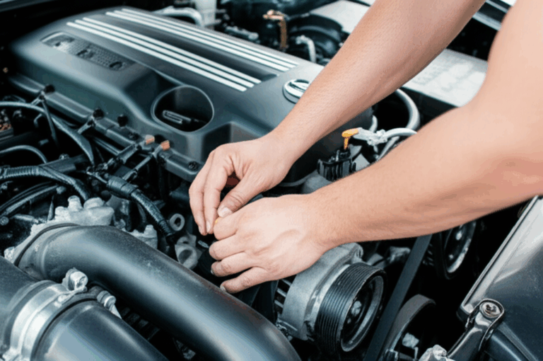
- Plan motor maintenance stator rotor checks with IR tests and vibration checks
If you manage these you cut causes of motor failure stator and causes of motor failure rotor. Your machines run longer. Your power transmission stator role stays solid.
What design choices drive cost and power density?
Cost drivers include:
- Material selection: Copper vs aluminum windings. High grade silicon steel vs standard steel. Permanent magnets for the rotor add cost yet boost power density.
- Winding complexity: Distributed vs concentrated. Hairpin windings vs round wire. Hairpin can pack more copper yet needs special tooling.
- Assembly: Coil insertion, rotor stacking, and balancing steps take time.
You can lower loss and raise output with better laminations. See how electrical steel laminations change the game. Quality stacks reduce core losses reduction and boost power factor. If you need a supplier you can review high grade electrical steel laminations and complete motor core laminations to hit targets fast.
Problem: Your motor runs hot and loud. Agitate: Heat eats insulation and noise scares customers. Solution: Use optimized cores like the stator core lamination and rotor core lamination options that cut eddy currents. Pair that with tighter air gap control and better cooling. You will hear and feel the change.
What materials matter in cores, windings, and frames?
- Core materials: Silicon steel with high magnetic permeability and low loss. Thin gauges. Clean edges. Coatings that insulate sheets. These traits reduce eddy currents and hysteresis loss.
- Windings: Copper gives low resistance and high fill. Aluminum costs less and weighs less. Pick based on budget and duty.
- Magnets: Permanent magnet rotors use high grade rare earth types in PM machines. They bring high power density at a cost.
- Frame and bearings: Strong frames hold things true. Good bearings reduce friction and last longer.
Do not forget transformers in your system. If you plan power electronics you will care about transformer lamination core choices too. EI and UI stacks like ei core and ui cores see wide use. They share the same loss rules you see in motors.
Quick buyer’s guide: How to pick the right machine
- Need simple and tough: Pick a squirrel cage induction motor. Low cost. Easy maintenance.
- Need high power factor and steady speed: Pick a synchronous motor. Use field winding in stator or rotor based on size and controls.
- Need speed control with low upkeep: Pick a BLDC motor with a permanent magnet rotor and an inverter.
- Need DC line and easy torque control: Pick a DC motor with a commutator and simple drives.
Make sure to match:
- Voltage and frequency control motor specs
- Variable speed drives stator rotor features
- Thermal management and insulation class
- Mechanical energy and load type
- Power conversion efficiency targets
Optional FAQ
Q: What is a stator in simple words?
A: The stator is the still part of a motor or generator. It makes or receives the magnetic field.
Q: What is a rotor in simple words?
A: The rotor is the part that spins. It makes torque in a motor or makes power in a generator.
Q: What makes a motor spin?
A: The stator creates a rotating field. The rotor sees the field and a Lorentz force pushes on its bars or coils. That makes torque.
Q: What is the role of the air gap?
A: The air gap lets flux pass from stator to rotor. A small even gap boosts torque and cuts noise.
Q: What is back EMF?
A: Back EMF is the voltage a motor creates as it spins. It rises with speed and opposes the supply. Drives use it to control current.
Q: Do we use slip rings in all machines?
A: No. Slip rings show up in wound rotors and many synchronous generators. Commutators show up in DC motors.
Summary: Key points to remember
- The stator stays still and makes or takes the magnetic field
- The rotor spins and makes torque in motors or voltage in generators
- The air gap size and shape matter for efficiency, noise, and vibration
- Losses come from copper, eddy currents, and hysteresis so use good laminations
- Cool the stator and rotor well to protect insulation and bearings
- Pick the right type: induction, synchronous, DC, or BLDC based on your job
- Use strong materials and tight build for high power density and long life
- For PM and BLDC builds match magnets and cores with care. Review the bldc stator core options if you chase compact power
References
- Chapman, S. J. Electric Machinery Fundamentals. McGraw-Hill.
- Fitzgerald, A. E., Kingsley, C., Umans, S. D. Electric Machinery. McGraw-Hill.
- IEC 60034-30-1 Rotating electrical machines – Efficiency classes of line operated AC motors.
- IEEE Industry Applications Society publications on motor losses, failures, and reliability.
- EPRI reports on motor reliability and maintenance best practices.
Additional Detail Sections
The stator: the stationary powerhouse
The stator is called the stationary powerhouse for a reason. It can house the field winding or the armature based on the machine. In induction motors it creates the rotating field. In many synchronous generators it holds the armature which sends power to the grid. In some designs the field winding in stator makes sense for cooling and access.
Key parts:
- Laminated core made of stacked sheets to limit eddy currents
- Windings made from copper or aluminum
- Frame to support and cool
You can pick a permanent magnet stator or a wound stator. PM stators show up in BLDC and PM synchronous drives. Wound stators are common in AC machines. Your choice depends on cost, control, and power factor needs.
The rotor: the rotating workhorse
The rotor gets the hard work done. It might be a squirrel cage rotor, a wound rotor, or a permanent magnet rotor. Salient pole rotor designs serve slow high torque synchronous machines. Cylindrical rotors handle high speed cases.
The rotor windings purpose depends on type. In induction designs the rotor bars carry induced current. In wound designs the rotor coils get current through slip rings. In DC motors the rotor is the armature that holds the main coils with a commutator. In PM motors magnets on the rotor set the field and the stator holds the power coils.
When you size a rotor watch magnetic poles in rotor, saturation, mechanical integrity, and balance. Good parts and good build reduce vibration and raise life.
The synergy: what happens in the air gap
Energy conversion happens in the air gap. The magnetic field generation stator meets the rotor. Flux linkages stator rotor change in time. That change induces EMF in the rotor or stator based on mode. The Lorentz force motor principle then turns current and flux into torque.
In a motor you can think of the stator as the teacher and the rotor as the student. The stator shows a rotating field lesson. The rotor follows and spins. In a generator the rotor gives the lesson while the stator learns and sends the grade as useful current. Simple story. Deep science.
Controls and speed: how drives help
Modern drives use variable speed drives stator rotor to adjust frequency and voltage. This changes the speed of induction motors and BLDC units. You can tune power factor and lower losses. You can set ramps to protect bearings and limit inrush current.
The drive also watches back EMF and slip. It can keep a synchronous motor locked or adjust induction speed. It helps with power transmission stator efficiency. You get better power conversion efficiency end to end.
A short look at generators
In generators you often see a synchronous machine. The generator excitation system feeds the rotor field winding via slip rings or a brushless exciter. The rotor can be salient pole or cylindrical based on speed. The stator acts as the armature and sends out three-phase power. This is how large power generation plants work.
Small sets can also be permanent magnet based. They use fixed magnets on the rotor. The stator coils pick up voltage when the shaft spins. Simple and robust.
Material science in motor cores
Core sheets use silicon steel laminations that balance magnetic permeability, strength, and low loss. The coating stops sheet-to-sheet currents. Good stacks trim eddy currents and hysteresis loss. For a full system you might also need transformer cores, so get to know ui lamination core and EI stacks as well. You can see more on EI stacks here: ei core laminations.
If you want one place to review options for motors start at the home for motor core laminations. You will find stator and rotor sets built to spec.
Pros and cons across rotor types
- Squirrel cage: Pros are rugged, cheap, low upkeep. Cons are limited start torque control.
- Wound rotor: Pros are adjustable start torque and soft start. Cons are brushes and rings to maintain.
- Salient pole: Pros are good for low speed power generation. Cons are large size.
- Cylindrical rotor: Pros are great for high speed. Cons are tight build and balance needs.
- Permanent magnet: Pros are high efficiency and power density. Cons are magnet cost and demagnet risk if overheated.
A quick word on linear and stepper motors
In a linear motor the stator and rotor stretch out. You get straight motion. In a stepper, teeth on stator and rotor pull into place step by step. Both use the same electromagnetism basics. Both use magnetic flux interaction. They just package it in a new way.
PAS wrap up for buyers and builders
Problem: Confusing choices slow your project. You guess on cores and windings. Your motor runs hot.
Agitate: Heat trips drives. Noise scares users. You miss deadlines.
Solution: Use proven laminations and clear specs. Start with electrical steel laminations. Pick a tight stator core lamination and a matched rotor core lamination. For BLDC consider a tuned bldc stator core. Then size windings, choose insulation class, and lock the air gap. You will hit your targets with less risk.
With the right stator and rotor you turn ideas into motion. You power the modern world with less waste and more value.