What is the Air Gap Between Rotor and Stator? Understanding Its Critical Role in Electric Motors & Generators
Table of Contents
- What is the Air Gap Between Rotor and Stator?
- What Do We Mean by “Air Gap”?
- Why Does the Air Gap Matter so Much?
- How Does the Air Gap Make Power and Torque?
- What Happens if the Air Gap Is Too Large?
- What Happens if the Air Gap Is Too Small?
- How Do You Choose the Right Air Gap Size?
- How Do You Measure and Maintain the Air Gap?
- How Do Speed, Cooling, and Materials Affect the Gap?
- What Do Standards and Testing Say?
- Case Studies and Fast Facts You Can Use
- Simple Science Corner: Fields, Flux, and Maxwell’s Rules
- Design Tools: FEA, CFD, and Smart Monitoring
- Where Does This Matter in Real Life?
- Quick FAQ
- Key Takeaways
The air gap sits between the rotor and the stator. It looks tiny. It drives big results. In this guide I show you what it is, why it matters, and how to get it right. You learn what happens when the gap is off. You also see how to measure it and how to keep it in line. Read on if you want less heat, less noise, more torque, and better efficiency.
What Do We Mean by “Air Gap”?
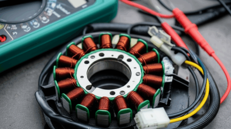
The air gap is the small mechanical clearance between the moving rotor and the fixed stator in an electric motor or generator. Think of a bike wheel in a tight frame. The wheel must spin. It must not rub. That small space lets motion and magnetic flux do their work.
People also call it the magnetic air gap or the electric motor air gap. In a generator air gap, the idea is the same. The gap lets the magnetic field cross from stator to rotor and back. This is how we get energy conversion. The air gap completes the magnetic circuit. It guides flux linkage and sets air gap reluctance and air gap permeability.
As a young engineer I learned this the hard way. I helped start a motor with a gap set too small. It squealed. It rubbed. It failed. Since then I watch the air gap length and air gap design like a hawk.
Why Does the Air Gap Matter so Much?
The gap sets how strong the magnetic pull can be. A tight gap gives stronger magnetic forces and better magnetic field distribution. That boosts torque production and can improve power factor. It can also lower magnetizing current and cut stray losses. That helps motor efficiency.
The gap also keeps parts safe. We need space so the rotor does not hit the stator during rotor dynamics events like shaft whip or bearing wear. We need room for air gap ventilation and air gap cooling. We need room for manufacturing tolerances. A proper rotor stator clearance reduces vibration and noise. It also holds down unbalanced magnetic pull (UMP) from air gap eccentricity.
This small space shapes machine lifespan and motor reliability. It shapes heat, core losses, copper losses, and even saturation effects in the core. Get it right. Your winding stays cool. Your laminations last. Your bearings stay happy. Your efficiency rises.
How Does the Air Gap Make Power and Torque?
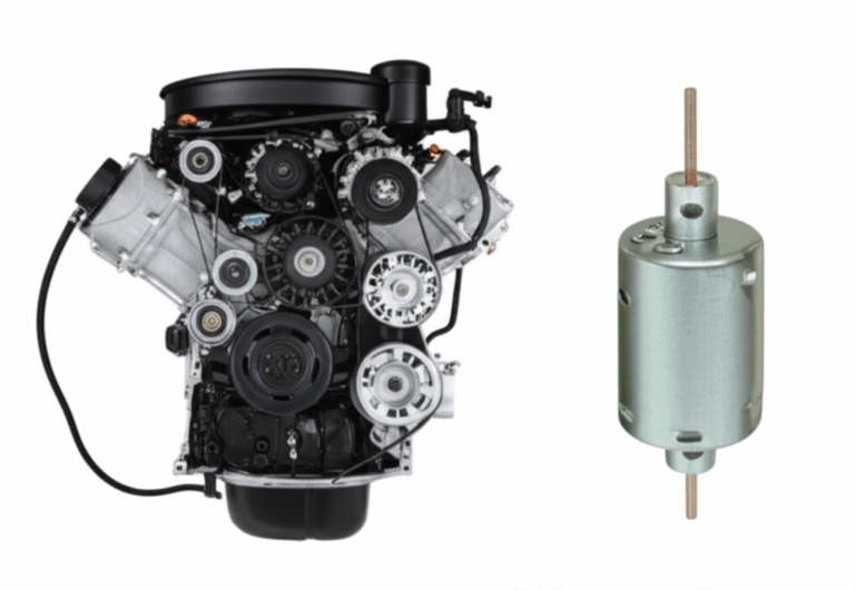
Here is the simple story. A current in the stator makes a magnetic field. That field crosses the gap. It links with the rotor. In an induction motor, that field induces rotor bar current in a rotor cage induction motor or in a wound rotor motor. Force appears. The rotor turns. We get torque.
In a synchronous motor or a permanent magnet motor (PM motor), the rotor has its own field. The gap lets the two fields couple. Strong coupling means strong torque. In a DC motor or BLDC motor you still rely on the gap to pass flux and to set back EMF. You also face cogging torque and ripple torque that the gap can tame.
In a generator, the rotor cuts flux in the stator. The gap sets the open circuit voltage, the short circuit current, and how much inductance variation we see with load. The gap is the doorway for energy flow. Open it too far and you lose power. Pinch it and you risk a crash.
What Happens if the Air Gap Is Too Large?
Problem: A large gap raises air gap reluctance. The field weakens. You need more magnetizing current. Current rises. Heat rises.
Agitate: With a large gap you get lower flux linkage and higher stray losses. Power factor drops. Efficiency drops. In permanent magnet motor air gap design you may push the magnets toward demagnetization risk during faults. Torque falls. The motor may not start heavy loads. It may trip on overcurrent. Your bill goes up. Your uptime goes down.
Solution: Set an optimal air gap. Use good magnetic material properties. Choose tight but safe manufacturing tolerances. Use precision stator slot geometry and rotor bar geometry. Select high quality electrical steel laminations for the stator and rotor cores to hold flux with less loss.
What Happens if the Air Gap Is Too Small?
Problem: A small gap can cause rubs. Heat builds fast from contact. You can get winding insulation breakdown, bearing failure, and even rotor lock.
Agitate: Rubbing makes noise and vibration. It can drive unbalanced magnetic pull higher as the rotor sits off center. Heat generation in motor spikes. Local hot spots can jump 10–50°C. You risk shorted turns and a full stop during peak load. A bad day gets worse when the shaft scores the stator.
Solution: Keep a safe mechanical air gap based on speed, load, and motion. Align the shaft. Watch alignment issues, foundation shifts, and bearing wear. Use condition monitoring and predictive maintenance with air gap sensors to catch air gap variations early. A tiny fix now can save a huge repair and overhaul later.
How Do You Choose the Right Air Gap Size?
You look at the type of electric machine first. Induction motor air gap is often small to limit magnetizing current. Synchronous motor air gap can be a bit larger. Permanent magnet motor air gap is often larger to soften cogging torque and allow flux weakening. DC motor gaps vary with brush gear. Stepper motor air gap and switched reluctance motor (SRM) gaps handle special slot harmonics and end winding effects.
Next you size for power rating and torque requirements. Big machines have larger physical gaps. They often keep smaller relative gaps as a percent of diameter. You also check operating speed and frequency. High speed rotors need more room for growth and whirl. You balance cooling requirements and thermal management. You keep magnetic saturation in check. You weigh cost and manufacturing tolerances. You choose an optimal air gap that serves both electrical and mechanical needs.
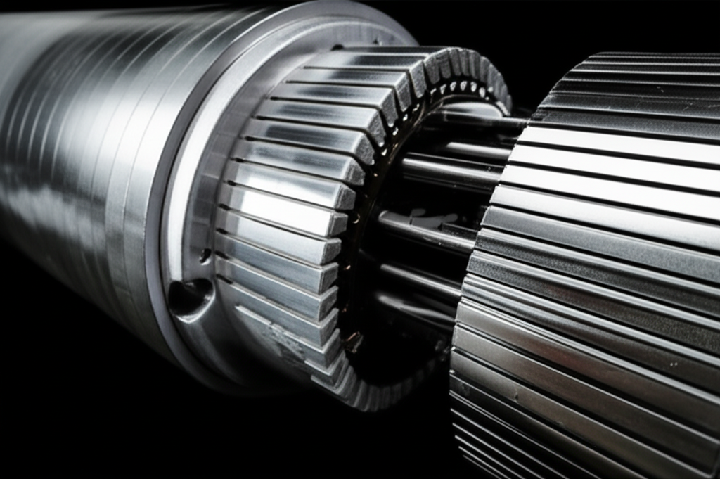
I also look at the build stack. The quality of the stator core lamination and the rotor core lamination will change the loss map and the flux path. Good stacks give you design optimization room. Poor stacks force a larger gap to fight heat and noise.
How Do You Measure and Maintain the Air Gap?
You can use a feeler gauge for a static check during assembly. You can also install air gap sensors for a dynamic air gap measurement while the machine runs. That helps you see air gap eccentricity and rotor-stator interaction under load. It helps you flag unbalanced magnetic pull before it hurts the bearings.
Set a simple plan. Inspect the gap during outages. Check alignment with the coupler in place. Check bearing condition. Track vibration due to air gap changes. Watch noise and air gap trends. Clean inlets to aid air gap ventilation. Use predictive maintenance to trend gaps over time. Replace worn parts before the rotor ever kisses the stator.
How Do Speed, Cooling, and Materials Affect the Gap?
High operating speed and high frequency push you to a slightly larger safe gap. The rotor grows with heat. It moves under load. Rotor dynamics matter at speed. You must allow for mechanical stresses and motion.
Cooling also changes the story. Strong air gap cooling or air gap ventilation helps. Better cooling cuts core losses and copper losses heat. That means less growth. That lets you run a tighter gap with less risk. Materials matter too. High grade electrical steel, silicon steel, copper, and aluminum choices change eddy currents, hysteresis, and saturation. Good steel can allow a tighter gap since losses fall. Smart winding configuration can cut inductance swings and reduce hum.
In some builds you will see axial air gap motors. In others you will see radial air gap motors. The geometry changes the cooling path and the flux path. The same core idea holds. Keep the gap even. Keep it clean. Keep it right.
What Do Standards and Testing Say?
Groups like NEMA, IEC, and IEEE set guides for motor design considerations, test methods, and safety. They do not set one gap for all. They guide manufacturing tolerances, vibration limits, and thermal classes. ISO 10816 sets vibration levels for severity checks. NEMA MG-1 explains insulation classes and gives rules for temperature rise.
We use finite element method (FEM) tools to test a design in software. We run finite element analysis (FEA) for fields. We run computational fluid dynamics (CFD) for cooling. We confirm magnetic circuit analysis and then prototype. We test power factor, efficiency, torque, and back EMF. We check open circuit voltage and short circuit current for a generator. We verify the gap under speed and load. Then we lock specs.
Case Studies and Fast Facts You Can Use
Here are useful ranges and effects. Use them with care. Always follow your data and your spec.
| Metric or Scenario | Typical Range or Value | Impact or Description |
|---|---|---|
| Radial air gap in induction motors | 0.2 mm to 2 mm | Smaller gaps cut magnetizing current. Larger motors use larger gaps in mm yet smaller relative gaps vs diameter. |
| Radial air gap in PM motors | 0.5 mm to 4 mm | Wider gaps reduce cogging torque and allow flux weakening. Useful for high speed and EV traction. |
| 10% air gap increase | 1–3% drop in efficiency | Higher magnetizing current raises copper loss and stray losses. |
| 10% air gap increase | 0.02–0.05 drop in power factor | More reactive power demand due to higher reluctance. |
| Rubbing in the gap | 10–50°C local hot spots | Fast damage to insulation and bearings. |
| 10% eccentricity | ~0.5 mm/s RMS rise in vibration | Higher UMP and faster bearing wear. |
| Overheat of insulation by +10°C | Up to 50% life loss | Heat speeds insulation aging by Arrhenius rule of thumb. |
| Wind turbine generator tweak | -0.1 mm better gap | ~1.5% more annual energy from less loss and better coupling. |
| EV traction motor with tight gap | 0.4 mm gap | 12% higher torque density and 7% lower volume with tight build tolerances. |
These are not strict rules. They show the trend. Keep the gap even and right. Your machine will thank you.
Simple Science Corner: Fields, Flux, and Maxwell’s Rules
We do not need hard math here. Still the electromagnetic theory helps. Maxwell’s equations tell us how magnetic fields and electric fields move and link. When current flows in the stator, it makes a field. That field crosses the gap. The rotor sees it. The rotor makes current or uses magnets. The two fields push on each other. That push makes torque.
The gap sets how easy it is for flux to cross. We call that permeability and reluctance. Air has low permeability. Steel has high permeability. So most flux wants to stay in the core. The air gap is the weak link in the magnetic circuit. If we make the gap bigger, the path gets harder. The motor must “push” with more magnetizing current to get the same flux. If we make the gap too small, parts can hit. We must find the sweet spot.
Design Tools: FEA, CFD, and Smart Monitoring
Modern teams use FEM with FEA to map magnetic field distribution and flux density in the air gap and in the stator and rotor. We look at slot harmonics. We study inductance variation and ripple torque. We then use CFD to model thermal management and the effect of air gap cooling and air gap ventilation. We want cool windings. We want low core losses and eddy currents. We want smooth fields with low hum.
We also use condition monitoring in service. We add air gap sensors. We trend vibration. We log noise. We watch power factor, efficiency, and magnetizing current. We predict motor failure analysis risks. This is predictive maintenance. It helps us avoid trips and plan repair and overhaul at the right time.
If you design or fix motors, take a hard look at your cores. High grade laminations matter. The right stacks carry flux with less heat. If you need help with high precision cores and stacks, review quality options like motor core laminations and specialized BLDC motor core laminations. Tight stacks support tight gaps.
Where Does This Matter in Real Life?
You see the air gap at work across many fields. In electric vehicle motors, a tight but safe gap boosts torque and power density. In wind turbine generators, gap control lifts power generation systems output and uptime. In industrial motor applications, such as pumps and compressors, the right gap saves energy every hour of the day. In HVAC fan motors, a good gap cuts noise and keeps air moving. In power plant machines and generator design, steady gaps mean steady power.
You also see air gaps in transformers at times. A transformer air gap is rare and used in some designs to set inductance or avoid saturation. The physics connects. The gap sets reluctance. It shapes flux. Good cores help in both worlds. That is why core quality is key. Smart builders choose proven electrical steel. They pick strong stacks like stator core lamination built to tight manufacturing tolerances.
Let me add one more note. If you hear new hum or feel new shake, do not ignore it. Vibration due to air gap change often starts small. Unbalanced magnetic pull grows over time. A quick test with a feeler gauge during a stop can catch a problem. A small shim or a new bearing can save a big motor.
Quick FAQ
Q: What is a good air gap for a small induction motor?
A: Many small motors run in the 0.2–0.6 mm range. It depends on size, poles, and build.
Q: Does a larger air gap always hurt?
A: No. It can reduce cogging torque in PM and BLDC drives. Still it often lowers efficiency and power factor.
Q: How do I know if the air gap is uneven?
A: Watch vibration and noise. Use air gap sensors or a careful feeler gauge check around the circle.
Q: Can software pick the best gap?
A: FEA and CFD help a lot. Field test still matters.
Q: Does core quality affect the gap choice?
A: Yes. Better laminations and magnetic material properties let you run tighter gaps with lower loss. See electrical steel laminations for examples of high grade stacks.
References
- NEMA MG-1, Motors and Generators
- IEC standards for rotating electrical machines
- IEEE Transactions on Energy Conversion
- ISO 10816, Mechanical vibration — Evaluation of machine vibration
- Standard electric machinery design textbooks and industrial maintenance guides
Key Takeaways
- The air gap is the small space between rotor and stator. It is vital for electromagnetism and safe spin.
- The gap controls magnetic flux, reluctance, magnetizing current, power factor, and torque.
- Too large a gap raises loss and cuts efficiency. Too small a gap risks rubs, heat, and failure.
- Gap size depends on machine type, size, speed, cooling, materials, and manufacturing tolerances.
- Measure with a feeler gauge or air gap sensors. Use predictive maintenance for condition monitoring.
- Use high quality cores and stacks to support tight, stable gaps. Consider rotor core lamination and stator core lamination when you design or upgrade.
- Apply FEA, CFD, and standards from NEMA, IEC, and IEEE to guide design optimization.
- In EVs, wind turbines, HVAC systems, pumps, compressors, and power generation systems, the right gap lifts uptime and lowers cost.
- Watch for air gap eccentricity and unbalanced magnetic pull. Fix alignment and bearing issues fast.
- Keep it simple. Keep it safe. Keep the air gap right for long machine lifespan and high motor reliability.