What Is an Outboard Motor? The Engineer’s Guide to Motor Laminations, Materials, and Manufacturing
Every design engineer on the water faces the same problem. You need reliable propulsion with high torque at low speeds. You must meet tight emissions or noise targets. You also have to hit cost and lead-time goals that won’t sink the program. Whether you work on a gasoline powerhead mounted to a transom or a next‑gen electric outboard pushing a tender or pontoon boat you run into the same core question behind the scenes. What do motor laminations do for you and how do you specify them without creating risk?
This guide answers that question in plain language. We’ll explain what an outboard motor is from a systems view then go deep on the stator and rotor laminations inside electric drives, starters, alternators, and trolling motors that live on the same boats. We’ll cover electrical steel choices, thickness trade‑offs, manufacturing routes like stamping vs laser cutting, and how assembly methods influence losses, NVH, and durability in harsh saltwater.
You’ll come away with a clear playbook you can use in design reviews and sourcing decisions.
In This Article
- Why This Matters: Efficiency, Heat, and Cost in Marine Motors
- Outboard Motor 101: A Clear, Practical Primer
- Core Physics: Eddy Currents, Hysteresis, and Why Laminations Work
- Material Options for Laminations: NOES, GOES, Cobalt, and More
- Manufacturing and Assembly: Stamping, Laser, Bonding, and Interlocks
- Matching Solutions to Applications: From Trolling Motors to High‑HP Outboards
- Measurements, Specs, and Standards You’ll Lean On
- Sourcing Smart: Cost, Quality, and Risk in Procurement
- FAQs and Common Pitfalls
- The Engineering Takeaway and Next Steps
Why This Matters: Efficiency, Heat, and Cost in Marine Motors
Marine propulsion is unforgiving. You fight corrosion, vibration, and parasitic drag all day. Add the market pressure. According to NMMA reporting for 2022–2023 outboard engines remain the dominant propulsion system in U.S. recreational boating with hundreds of thousands of units sold each year. Four‑stroke engines lead the gasoline segment due to fuel efficiency and noise while electric outboards and high‑thrust trolling motors keep growing on the back of better lithium‑ion battery systems. The demands on every watt and every newton of thrust keep climbing.
For engineers and product designers several things drive lamination choices:
- Efficiency targets and heat. Eddy currents and hysteresis waste energy as heat in the stator and rotor core. You feel that as lower range on a battery pack or higher cooling loads on a compact powerhead frame.
- Power‑to‑weight ratio. Outboards live and die by this number. Laminations influence peak flux density and mechanical stiffness which feed into torque per kilogram.
- NVH. Blade passage harmonics and gear noise grab attention. Torque ripple from the electromagnetic design and lamination skew or segmentation can make the difference between a smooth hum and a harsh buzz.
- Reliability in saltwater. You have to think about coating systems, interlaminar insulation, and crevice corrosion around bonding lines or welds.
- Cost and lead time. Tooling for progressive stamping pays off at volume. Laser cutting wins prototypes or short runs. Your production plan must match the realities of your bill of materials and schedule.
Procurement teams weigh a related set of risks. Material availability for NOES grades. Burr height and flatness control. Cpk on critical OD and ID fits for bearings and seals. Certification to ASTM and IEC test methods. You want a design that performs and a supply chain that holds water.
Outboard Motor 101: A Clear, Practical Primer
Let’s set the scene with a quick definition so we talk the same language. An outboard motor is a self‑contained marine engine with an integrated gearbox and propeller mounted outside the hull on the boat’s transom. That external engine configuration keeps the interior open for people and gear. It also simplifies installation, service, and replacement.
Here’s the working anatomy:
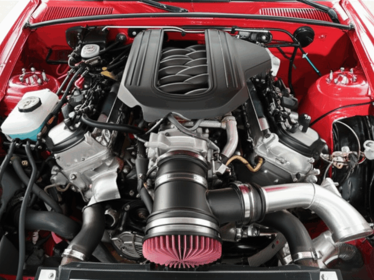
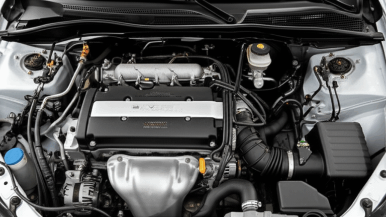
- Powerhead. This is the combustion engine or electric motor on top. In gas outboards you’ll find cylinders, pistons, a crankshaft, a fuel system with EFI or DFI, and an ignition system with spark plugs. In electric outboards you’ll find a high‑efficiency BLDC or PMSM machine driven by a marine‑rated inverter and a lithium‑ion battery pack with a robust BMS.
- Midsection. This connects the powerhead to the lower unit. It houses the vertical driveshaft, exhaust passages, and the cooling water path that routes from the water intake past the thermostat to the jacket then out with the exhaust. The rubber impeller in the water pump is the heart of that cooling system.
- Lower unit. This is your gearbox. Forward, neutral, reverse live here with a gear ratio chosen for the propeller. The propeller shaft exits through the anti‑cavitation plate and skeg region. Many outboards route exhaust through the propeller hub for noise reduction.
- Propeller. It converts engine torque into thrust. Diameter, pitch, and blade count set your acceleration, top speed, and fuel efficiency.
- Controls and steering. Small motors use a tiller handle with throttle and choke or primer bulb for start‑up on carbureted units. Larger engines use remote controls, steering wheels, and electronic throttle. Trim and tilt lift the motor for shallow water drive which helps in rivers or when beaching.
Common types:
- Two‑stroke vs four‑stroke gasoline outboards. Modern four‑strokes are quieter with lower emissions and better fuel efficiency which is why they’ve taken over. Direct‑injection two‑strokes still serve some use cases due to power density.
- Electric outboards. These are quiet and emission‑free at the point of use which fits no‑wake lakes and eco‑sensitive areas. Torque comes in strong from zero RPM which suits fishing boat motors, dinghy engines, and tenders.
- Jet drive outboards. These replace the propeller with an impeller which lets you run in very shallow water with less risk from rocks or debris.
Specs and features:
- Horsepower and torque. From portable outboards at 2–20 HP to high horsepower twins or triples north of 300 HP. Torque at the propeller determines acceleration and holeshot performance.
- Shaft length. Short shaft, long shaft, and extra‑long shaft match hull design and transom height.
- Electronics and integration. NMEA 2000 networks tie in to GPS and sonar. OEM platforms like Mercury SmartCraft or Yamaha Command Link layer diagnostic and control capabilities. Alternators and voltage regulators support marine batteries and onboard loads.
- Safety gear. A kill switch and lanyard are non‑negotiable on any boat.
Brands you know and trust include Mercury Marine, Yamaha Outboards, Honda Marine, Suzuki Marine, Tohatsu, and Torqeedo for electric. Evinrude left the market yet the installed base remains significant. Regulatory bodies like the U.S. Coast Guard, the EPA, and CARB set safety and emissions standards you must honor.
That’s the context. Now let’s zoom into the lamination stack inside the electrical machines that increasingly power outboards or support them with starting, charging, and trolling.
Core Physics: Eddy Currents, Hysteresis, and Why Laminations Work
If changing magnetic fields are a river then eddy currents are the little whirlpools that spin off boulders. They look benign yet they steal energy and churn it into heat. That is exactly what happens inside a solid steel motor core. A rotating magnetic field induces circulating currents in the core which waste power and raise temperature. You limit those losses by breaking the core into thin electrically insulated sheets called laminations. Each sheet blocks current flow across its thickness which shrinks the whirlpools and reduces heat.
Two loss mechanisms matter most:
- Eddy current loss. It scales roughly with the square of lamination thickness and with the square of frequency at a given peak flux density. Halve the lamination thickness and you cut that loss by a factor of four all else equal. Increase your PWM carrier frequency or your mechanical RPM and eddy losses rise fast.
- Hysteresis loss. This is the energy you spend to magnetize and demagnetize the material every cycle. It depends on the area of the B‑H loop which ties to coercivity. Lower coercivity means less loss. Alloy composition and processing set that property.
A few other fundamentals to anchor your mental model:
- Magnetic permeability. Think of it like how easily field lines flow through a material. A sponge soaks up water easily which is what high permeability does for flux. You want high permeability up to your operating flux density which improves torque production and reduces magnetizing current.
- Saturation flux density. Push beyond this and the material stops carrying proportionally more flux which caps torque and spikes copper loss.
- Interlaminar insulation. Each lamination has a thin inorganic or organic coating that adds electrical resistance between sheets. That coating both reduces eddy currents and influences bonding or welding choices.
For rotating machines in outboards and trolling motors you almost always use non‑oriented electrical steel (NOES). Grain oriented electrical steel (GOES) excels in transformers and EI or UI core shapes because it channels flux well in one direction yet it performs poorly when the flux rotates. Save GOES for your onboard transformer or charger where it shines.
If you want a deeper refresh on the fundamentals you can skim IEC 60404 for magnetic test methods and ASTM A677 or A683 for sheet steel specs. IEEE Transactions on Magnetics is the go‑to for application‑level studies.
Material Options for Laminations: NOES, GOES, Cobalt, and More
You have a clear goal. Maximize performance per dollar without creating supply risk. Picking the right grade of electrical steel is the biggest lever.
- Non‑oriented electrical steel (NOES). Your default for rotating machines. It comes in grades with varied silicon content and thickness from about 0.1 to 0.65 mm. Higher silicon cuts eddy currents and hysteresis which reduces loss. It also reduces saturation slightly and can make the material more brittle.
- Typical choices for BLDC or PMSM in electric outboards run 0.2–0.35 mm thick depending on speed and switching strategy. Thinner gauges reduce loss at high frequency harmonics that come from inverter PWM or cogging effects.
- You can review the fundamentals and options here: electrical steel laminations.
- Silicon steel. This is the common shorthand for electrical steel due to the silicon alloying that enables lower loss. For a broad overview of grades and coatings see silicon steel laminations.
- Grain oriented electrical steel (GOES). Ideal for transformers and inductors which see unidirectional flux. You’d choose GOES for an onboard charger, a transformer lamination core, or an EI or UI lamination in power conversion. You would not select it for a rotating motor core in a propulsive outboard.
- Cobalt‑iron alloys. When you chase maximum power density you may consider 49% cobalt alloys which deliver higher saturation flux density and good strength at temperature. They come with much higher raw material cost and more challenging machining or stamping. Aerospace or defense marine applications sometimes justify that trade.
- Amorphous and nanocrystalline metals. Fantastic at very high frequency due to ultra‑low hysteresis and eddy current loss. They are brittle and hard to machine which limits use in traditional motor stacks. You will see them in high‑frequency transformers and some axial flux prototypes.
- Stainless steel. It is corrosion resistant and mechanically tough. It performs poorly magnetically due to low permeability and high losses unless you use specialized magnetic grades which still lag NOES. It belongs in housings, shafts, and fasteners not in the magnetic circuit.
Insulation coatings deserve a spotlight. Inorganic phosphate coatings handle heat and bond well yet they reduce stacking factor slightly. Organic coatings offer good punchability and can enable bonded stacks with film layers. Coating class and thickness matter because they set interlaminar resistance, weldability, and core fill factor.
A note on environmental and regulatory context. EPA and CARB emission rules pushed four‑stroke gasoline engines to higher efficiency with noise reduction. Electric outboards ride similar pressure toward clean operation. Lower core loss means smaller heatsinks or less coolant flow which reduces noise and weight. It also boosts range and cuts total cost of ownership for commercial users.
Manufacturing and Assembly: Stamping, Laser, Bonding, and Interlocks
Your manufacturing route shapes performance, cost, and schedule. There is no one right answer. Match the method to volume, geometry, and tolerance needs.
- Progressive die stamping. The workhorse for volume. Low cost per part once tooled. Excellent repeatability and burr control if your die is well designed and maintained. It supports features like notches for interlocks and stack alignment. You must budget for die cost and lead time and you should plan for die maintenance over the program life.
- Laser cutting. Perfect for prototypes, engineering validation, or low‑volume production with complex geometries. Minimal tooling, quick changes, and good dimensional accuracy. It can add a heat‑affected zone that increases local loss near edges which you can mitigate with process tuning and post‑processing.
- Wire EDM and waterjet. Niche options for very tight tolerance or special alloys where burrs and HAZ must be minimal. Slow cycle times drive cost.
- Fine blanking. Delivers sharper edges and reduced burrs in thicker gauges. Tooling cost is high.
Stacking and joining methods affect magnetic performance, rigidity, corrosion risk, and NVH.
- Interlocking tabs. Think LEGO bricks. Tabs form during stamping and snap together during stacking which yields a rigid core without welding. It preserves magnetic properties since you avoid local heat. It works best on geometries that can accept small tab features without impairing slot fill or winding insertion.
- Bonded stacks. Adhesives or thin organic films create a monolithic core with excellent damping for NVH. They also improve interlaminar insulation and can limit fretting in high‑vibration outboard installations. Adhesives must be compatible with your cooling fluids and saltwater service. Cure temperature must not damage insulation class.
- Riveting and cleating. Simple and robust for larger frames or transformer cores. They add local stress points which can influence noise and loss.
- Welding. Strong and fast. Local heat can degrade insulation and raise loss if not controlled. You may need post‑weld stress relief which has its own risks for coatings.
- Skewing and segmentation. Skewing the rotor or stator teeth reduces cogging torque and torque ripple which lowers acoustic noise. Segmented stators ease winding but add joints that need tight insulation control.
Geometry details matter. Burr direction should point away from flux paths where possible. Tooth tip radius influences local saturation and torque ripple. Rotor lamination runout and stack straightness control air‑gap variation which impacts humming or whining you hear at certain RPM bands.
If you want to see how the parts fit into the full assembly these resources will help:
- Stators and what to watch in stack build and insulation: stator core lamination
- Rotors, skew options, and mechanical fits for shafts and magnets: rotor core lamination
- The complete picture from blank to finished core: motor core laminations
Matching Solutions to Applications: From Trolling Motors to High‑HP Outboards
Different boats and duty cycles drive different lamination choices. Match the stack to the job, not the other way around.
- Trolling motors and auxiliary drives. These low‑noise, low‑speed BLDC motors help anglers hold position silently while the main fishing boat motor idles. You typically prioritize thin NOES gauges around 0.2–0.3 mm to reduce eddy losses at switching frequencies that can sit in the tens of kilohertz. Bonded stator stacks with skewed teeth can cut acoustic tones that spook fish.
- Electric outboards for dinghies, tenders, and small pontoons. Torque at low RPM dominates. You want a robust stator slot design that supports high slot fill with heavy magnet wire or hairpins. Lamination thickness of 0.27–0.35 mm often balances cost and loss well for machines that spin a few thousand RPM with field‑oriented control. If you push higher speed you may go thinner.
- Hybrid or full‑electric center consoles and commercial boats. Reliability and serviceability rule. Consider segmented stators that simplify replacement and field service. Cobalt alloys can help where you chase extreme power density though they raise BOM cost sharply.
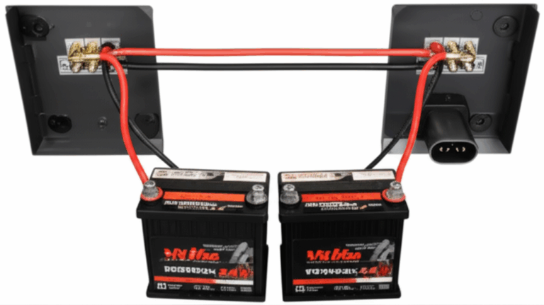
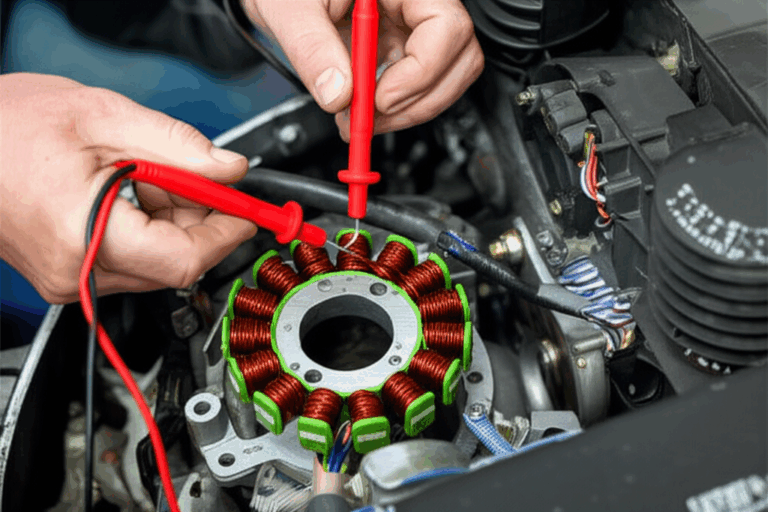
- Gasoline outboards with starter motors and alternators. You still care about lamination choices. Starters want high torque per volume which benefits from high permeability and careful slot geometry. Alternators crave low loss at a range of speeds. Good electrical steel pays dividends in battery charging performance which keeps onboard electronics on NMEA 2000 networks stable.
- Jet drive outboards in shallow water. Impeller load introduces different torque ripple patterns. Skewing the rotor or stator can suppress unwanted vibration which protects housings and seals.
- Multi‑engine setups on center console boats. Synchronization across engines through integrated controls like SmartCraft or Command Link depends on clean electrical power. Good alternator laminations and voltage regulation reduce ripple that can disturb sensitive electronics like sonar and GPS.
For saltwater usage pay attention to corrosion. Zinc anodes protect exposed metal components. Inside the motor cavity coatings on laminations help repel moisture during long idle periods. Freshwater flush procedures after runs in the ocean reduce salt buildup that can creep into housings. You should also consider anti‑fouling measures near water intakes because growth restricts cooling flow and raises motor temperature.
Measurements, Specs, and Standards You’ll Lean On
Data builds trust in design reviews. These are the numbers and methods you’ll use when you compare lamination options.
- Core loss. Suppliers report loss in W/kg across peak flux density and frequency. You may see values like P1.5/50 which means loss at 1.5 Tesla and 50 Hz. For motor duty you care about higher frequency harmonics from PWM and slotting. Ask for curves that extend into your real spectrum not just at 50 or 60 Hz. Epstein frame testing and single sheet testers per IEC 60404 are common references.
- B‑H curve and permeability. Plot magnetization versus field to understand how quickly the material approaches saturation. Lower coercivity reduces hysteresis loss. You can target operating points that sit on the sweet spot of the curve rather than near saturation which drives heat and torque ripple.
- Stacking factor. This is the ratio of steel thickness to total stack thickness. Insulation and bonding reduce it slightly. Accurate stacking factor matters in mass and torque calculations.
- Mechanical tolerances and burrs. Specify maximum burr height and preferred burr direction. Watch OD and ID tolerances for bearing fits and for minimal air‑gap variation. Flatness and parallelism affect assembly and NVH.
- Coating class and compatibility. Call out the insulation coating type per your bonding or welding method and your thermal class. Verify chemical compatibility with oils, coolants, and saltwater.
- Thermal limits. Pair lamination choices with winding insulation class and expected case temperature. Electric outboards often target increased thermal headroom for reliability which favors low‑loss laminations to reduce internal self‑heating.
Standards worth citing on drawings and in supplier contracts include:
- IEC 60404 series for magnetic property measurement
- ASTM A677 and A683 for non‑oriented electrical steel sheet
- ASTM A876 for GOES in transformer use
- ISO 2768 and ISO 286 for general machining and fit tolerances where applicable
- IPC/UL thermal classes for insulation systems
When you integrate stator and rotor designs with electronics also track EMC. Clean switching and proper shielding protect radios, GPS, and fish finders on your NMEA 2000 network.
Sourcing Smart: Cost, Quality, and Risk in Procurement
Let’s talk business. You balance upfront tooling, piece price, schedule, and quality risk. A simple framework helps.
- Volume vs tooling. Progressive stamping wins at scale. You amortize die cost across thousands of pieces which drops your unit price. Laser cutting wins development speed and design agility which pays off early.
- Supplier capability. Ask for prior builds in similar thickness and alloy. Review burr control, deburring methods, and stack joining options. Check that the supplier can certify magnetic properties to your specified standard and that they can provide heat lot traceability.
- Quality controls. Define incoming inspection for lam thickness, insulation integrity, and burr height. Implement Cpk targets for critical dimensions like stator ID and rotor OD. Add audit testing for core loss if the program justifies it.
- Packaging and corrosion control. Laminations ship best in sealed, humidity‑controlled packaging with VCI paper. Store them in dry areas to preserve insulation coatings.
- Regulatory and sustainability. EPA rules and local regulations shape materials and surface treatments. Electrical steels are recyclable which helps your program’s sustainability report. Confirm ROHS and REACH compliance for coatings and adhesives.
When you spec the lamination stack include a drawing note that lists:
- Material grade and thickness with allowed alternatives
- Insulation coating type and thickness range
- Stack height and stacking factor target
- Joining method and any requirements for skew or segmentation
- Maximum burr height and preferred burr direction
- Post‑processing such as stress‑relief anneal if needed
Being precise on paper reduces back‑and‑forth and avoids surprises on the shop floor.
FAQs and Common Pitfalls
- How thin should I go on lamination thickness for a BLDC electric outboard?
- Start with 0.27–0.35 mm for mid‑speed machines that use field‑oriented control with PWM in the 10–20 kHz range. Drop to 0.2–0.25 mm if core loss still dominates your thermal budget. Run the loss model with your actual harmonic spectrum not just the fundamental.
- Can I laser cut production parts for an electric outboard?
- You can if the volumes are modest and if you control HAZ and burrs. Many teams laser cut during DV and PV then move to stamping for SOP once the design stabilizes.
- Do bonded stacks handle saltwater environments?
- Yes with the right adhesive and surface prep. Pick a marine‑compatible adhesive system and validate in salt fog per ASTM B117. Bonded stacks often reduce NVH which is a bonus on boats.
- Should I skew the rotor, the stator, or both?
- Skewing the rotor laminations is common since it avoids slot‑tooth alignment harmonics while keeping winding insertion straightforward. Skew the stator when rotor constraints exist. Either way confirm you meet torque ripple and efficiency targets with your chosen skew angle.
- Where do rotor magnets fit into this lamination conversation?
- In interior permanent magnet designs the rotor lamination geometry sets flux paths and mechanical strength. In surface‑mounted magnet designs lamination slots and bridges hold magnets under high centrifugal loads. Your rotor stack is every bit as critical as the stator stack.
- Do gas outboards benefit from lamination optimization?
- The propulsion comes from the combustion engine and propeller yet the starter motor and alternator do benefit. Lower loss alternators deliver cleaner DC which keeps electronics healthy and batteries happy.
The Engineering Takeaway and Next Steps
Here’s the distilled guidance you can carry into your next design session.
- Define the real operating spectrum. Model losses with your PWM harmonics, slotting harmonics, and mechanical speed, not just the nominal frequency.
- Pick NOES and gauge thickness to meet efficiency and thermal goals. Go thinner as frequency and loss climb since eddy loss scales with thickness squared.
- Choose manufacturing based on volume and geometry. Stamp at scale for cost and repeatability. Laser cut when agility and complexity matter most.
- Lock down stack joining early. Interlocks preserve magnetic properties and cost less. Bonding improves NVH and often helps in boats where vibration is brutal.
- Control burrs, flatness, and stack factor. Small mechanical misses show up as noise and heat on the water.
- Think system. Materials, coatings, and joining must survive saltwater, vibration, and variable loads. Design for service with replaceable segments when possible.
- Align procurement and engineering. Specify standards and test methods. Demand traceable magnetic data. Protect your supply chain with approved alternates.
If you want a compact overview of how all these elements come together in practice take a look at these primers:
- Broad overview of materials and options: electrical steel laminations
- Material family details and trade‑offs: silicon steel laminations
- Stator design and assembly considerations: stator core lamination
- Rotor geometry and joining choices: rotor core lamination
- From blanks to finished stacks in production: motor core laminations
Final thought. Outboards simplify propulsion because they keep everything outside the hull. Laminations simplify power conversion in the same spirit. They turn messy magnetic whirlpools into ordered flow which buys you torque, range, and reliability. Use that to build a motor that runs cool, pushes hard, and keeps your crew smiling.
—
Appendix: Quick Marine Context Checklist for Engineers
If you’re aligning a lamination stack to a specific outboard platform, sanity‑check your spec against these system notes so you avoid surprises later.
- Hull design and transom height influence shaft length which changes propeller loading and load profile on the motor or gearbox.
- Trim and tilt settings change thrust lines which can alter vibration modes and perceived noise. Tie NVH test plans to trim range.
- Cooling system behavior depends on water intake geometry, impeller condition, and thermostat set points. Validate core loss at elevated coolant temperatures which occur with partial blockage or hot saltwater.
- Electronics integration over NMEA 2000 should include EMC checks around the inverter for electric outboards and around alternators on gas outboards.
- Saltwater usage demands freshwater flush and periodic checks of anodes. Plan coatings on laminations and housings for that environment.