What Is an Induction Motor? My Complete Guide to AC Asynchronous Motors
Table of Contents
- Introduction: Why Induction Motors Keep Showing Up in My Life
- What Exactly Is an Induction Motor?
- How an Induction Motor Works
- The Rotating Magnetic Field
- Induction in the Rotor
- Torque Production and Lorentz Force
- Slip and Synchronous Speed
- The Key Components You Should Know
- Stator and Laminations
- Rotors: Squirrel Cage vs Wound Rotor
- Air Gap, Bearings, Frame, and Cooling
- Enclosures and Standards
- Types of Induction Motors
- Three-Phase vs Single-Phase
- Starting Methods: DOL, Star-Delta, Soft Starters
- Special Variants: Shaded Pole, Capacitor-Start/Run, Linear Induction
- Torque-Speed Characteristics, Power Factor, and Efficiency
- Slip, Torque, and Load Behavior
- Core, Copper, and Mechanical Losses
- Power Factor at Light Loads
- Starting and Speed Control
- Soft Starters vs VFDs
- Open-Loop vs Closed-Loop Control
- Harmonics and Power Quality
- Regenerative Braking
- Selecting and Sizing an Induction Motor
- Load Types and Duty Cycle
- Insulation Class, Temperature Rise, and Protection
- NEMA/IEC Frames, MCCs, and Protection Devices
- Maintenance, Reliability, and Troubleshooting
- Predictive Maintenance: Vibration and Thermography
- Common Faults and What I Check First
- Rewinds, Remanufacturing, and When to Replace
- Applications: Where Induction Motors Shine
- Induction Motors vs Other Motors
- DC, BLDC, PMSM, Stepper, and Synchronous
- Servo Motor vs Induction Motor
- Efficiency and the Future
- IE3, IE4, and IE5
- IoT, Smart Grids, and Advanced Materials
- Conclusion: The Enduring Value of the Asynchronous Workhorse
Introduction: Why Induction Motors Keep Showing Up in My Life
I didn’t fall in love with induction motors in a classroom. I learned to respect them in the field. The first time I traced a production line shutdown back to a failed motor bearing I realized something simple. These machines make the modern world move. Pumps, fans, compressors, conveyors, HVAC units, you name it. If it spins in industry there’s a good chance an induction motor sits behind it.
Over the years I’ve sized motors for conveyors, tuned variable frequency drives on pump stations, and opened more terminal boxes than I care to admit. The pattern never changes. Induction motors deliver reliable torque at a fair price and they keep doing it for years. No fuss. No brushes. Minimal maintenance. When people ask me “what is an induction motor” I don’t just give a definition. I show them how it works, why it dominates, and what to watch out for. That’s what you’ll get here.
What Exactly Is an Induction Motor?
An induction motor, also known as an asynchronous motor, is an AC motor where the rotor current comes from electromagnetic induction. The stator creates a rotating magnetic field. That field induces current in the rotor bars or coils. The induced current interacts with the stator’s field and produces torque. No direct electrical connection to the rotor in the common squirrel cage design. No brushes. No commutator.
Three things define it:
- AC powered: It runs on alternating current.
- Induction principle: Rotor current is induced, not wired in.
- Asynchronous behavior: The rotor runs slightly slower than the stator field. That difference is “slip.” Slip makes induction possible.
I like to call it the “workhorse” because it is. In factories, commercial buildings, and homes. Motors consume about 70% of industrial electricity. A huge chunk of that goes to induction motors. That number alone tells you how important they are.
How an Induction Motor Works
When I explain this to new technicians I start with a simple analogy. Imagine a merry-go-round of magnetic poles spinning around inside the stator. The rotor wants to chase it. It never quite catches up. That gap is slip. It’s the secret ingredient.
The Rotating Magnetic Field
Feed a three-phase AC supply into the stator windings and you create a rotating magnetic field (RMF). The windings sit 120 electrical degrees apart. The currents are 120 degrees out of phase. Those two facts combine to produce a magnetic field that rotates at a speed we call synchronous speed.
The formula for synchronous speed is: Ns = 120 × f ÷ P
- Ns in RPM
- f in Hz
- P is the number of poles
At 50 Hz with 4 poles, Ns = 1500 RPM. At 60 Hz with 4 poles, Ns = 1800 RPM.
Induction in the Rotor
At standstill the rotor sees the rotating magnetic field rushing by. Faraday’s law says changing magnetic flux induces voltage. The rotor bars or windings pick up an induced EMF. Since the rotor circuit is shorted, current flows. That current creates its own magnetic field.
Torque Production and Lorentz Force
Here’s where Lenz’s law shows up. The rotor’s induced field opposes the relative motion. In practical terms the rotor pulls into step with the rotating field and starts spinning with it. The Lorentz force on the rotor conductors produces torque. The rotor speeds up as the load allows. It always stays slightly behind the synchronous field so induction can continue.
Slip and Synchronous Speed
Slip s = (Ns − Nr) ÷ Ns. It’s usually a small number under rated load. If the rotor catches up to Ns the relative motion goes to zero. Induction stops, current drops, torque disappears. So the rotor must lag. That lag is slip and it adjusts with load. More load requires more torque, so slip increases a bit to induce more rotor current and deliver that torque.
In my pump applications a 4-pole motor on 50 Hz usually runs near 1470 RPM under rated load. That’s roughly 2% slip. Light loads bump the speed closer to 1490. Heavy loads pull it down to 1450 or so.
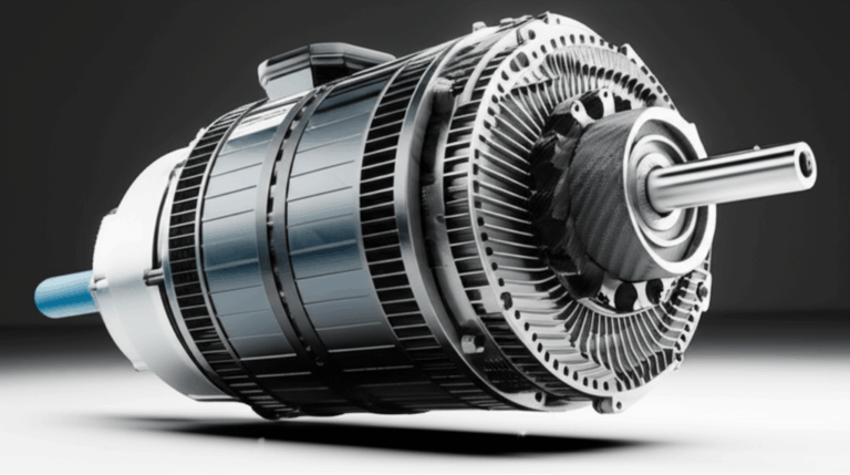
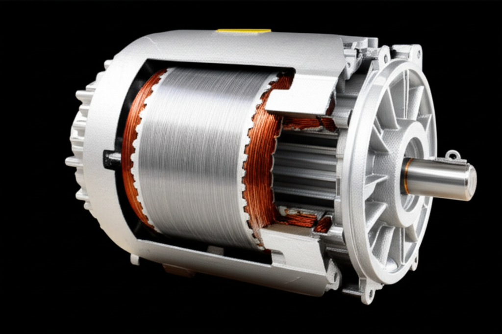
The Key Components You Should Know
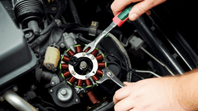
When you open a motor you see steel, copper, and good mechanical bones. The quality of those core parts matters. I pay close attention to laminations, bearings, and cooling paths. Small details often decide whether a motor runs cool and quiet or hot and noisy.
Stator and Laminations
The stator is a laminated steel core with slots that hold copper windings. Those laminations reduce eddy current losses in the core. Better laminations mean lower core losses and better efficiency. I’ve seen quality differences show up as temperature rise on long runs.
If you want the deep dive on stators look at the role of the stator core lamination and how lamination quality impacts loss and magnetics. The short version is simple. Thin, high-grade electrical steel with proper insulation between sheets keeps losses down.
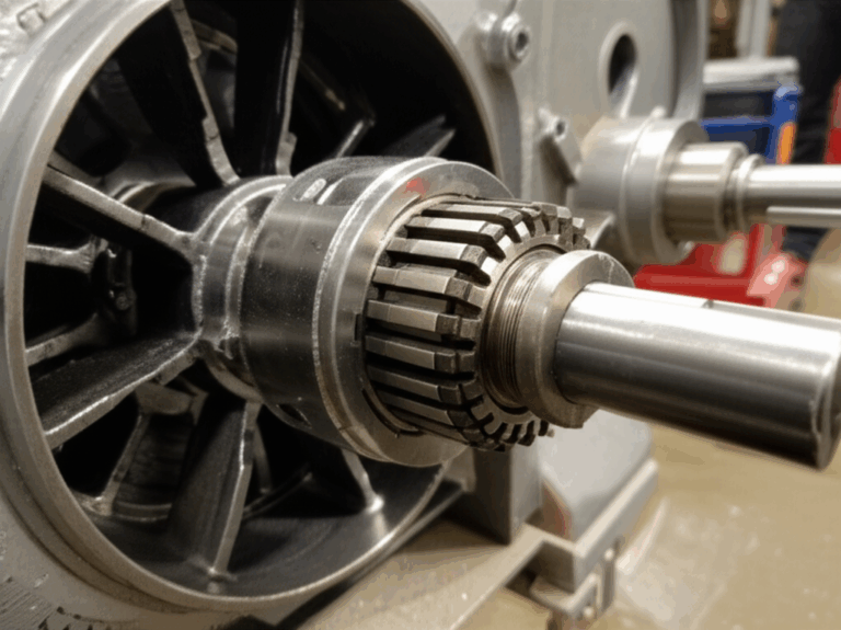
Rotors: Squirrel Cage vs Wound Rotor
- Squirrel cage rotor: The most common. It uses aluminum or copper bars cast or inserted into slots and shorted at both ends by end rings. It’s rugged and maintenance-light. I prefer squirrel cage motors for pumps, fans, and conveyors because they just run.
- Wound rotor: It uses insulated windings on the rotor connected through slip rings and brushes to external resistors. It can deliver high starting torque and offers some speed control via rotor resistance. I’ve used them on heavy-start applications like crushers. They work, though they need more maintenance.
Quality lamination and rotor design matter just as much in the rotor. If you want to see why, check the basics of rotor core lamination. Rotor bar geometry, material, and lamination stack details influence slip, efficiency, and torque ripple.
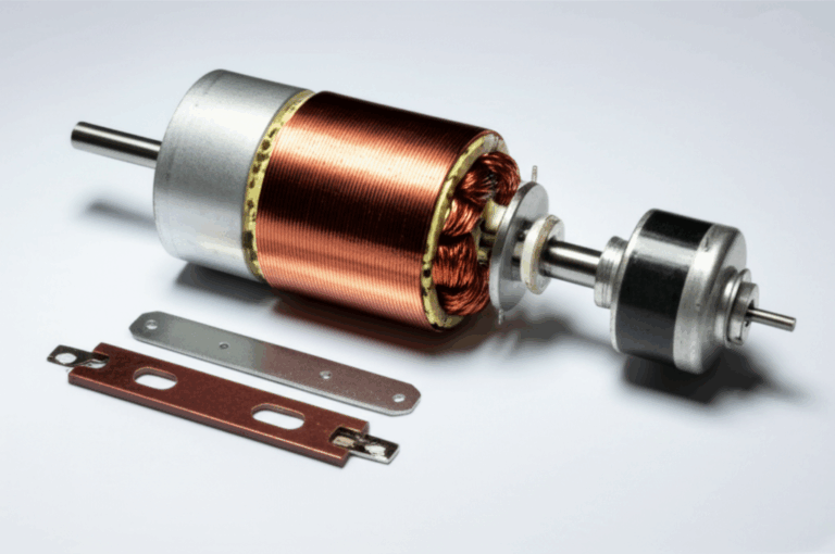
Air Gap, Bearings, Frame, and Cooling
- Air gap: Small gaps improve performance but they tighten tolerances. Too small and you risk rubs if bearings fail. Too large and magnetizing current rises.
- Bearings: Most induction motors use deep-groove ball bearings. Large motors may use roller or sleeve bearings. Grease quality, re-lube intervals, and seals make or break reliability.
- Frame and housing: The frame dissipates heat. Finned housings and a shaft-mounted cooling fan help move hot air away. Good airflow path means lower temperature and longer insulation life.
- Terminal box: I always check for tight lugs and proper strain relief. Loose connections cause heat and arcing.
Enclosures and Standards
Common enclosure types:
- TEFC (Totally Enclosed Fan Cooled): The most common in industry.
- ODP (Open Drip Proof): Cheaper and cooler running in clean, dry spaces.
- TEAO (Totally Enclosed Air Over): Fans and blowers that rely on process air.
- IP ratings under IEC describe ingress protection levels.
You’ll also see:
- NEMA and IEC standards for frames, dimensions, and performance.
- IEEE guides for motor testing and application.
- UL compliance for safety in North America.
Manufacturers like ABB, Siemens, General Electric, WEG, Toshiba, Mitsubishi Electric, Schneider Electric, Rockwell Automation, and others build solid machines. Pick a product that meets NEMA or IEC motor standards and suits your environment.
Types of Induction Motors
I split them two ways: by supply type and by rotor construction.
Three-Phase vs Single-Phase
- Three-phase induction motor: Self-starting and efficient. Industry loves them because they run smoothly, start reliably, and have a good power factor compared with single-phase options.
- Single-phase induction motor: Needs a starting method since single-phase power creates a pulsating field. Common methods include capacitor-start, capacitor-run, and shaded pole. You’ll see these in domestic appliances like washing machines and refrigerators. They can be noisy and less efficient but they get the job done.
Starting Methods: DOL, Star-Delta, Soft Starters
- Direct On-Line (DOL): Simple and common for small motors. It slams full voltage across the windings. You get high inrush current and a strong starting torque.
- Star-Delta starting: Reduces starting current for larger motors. Start in star to lower voltage per phase then switch to delta for run. It’s a classic method for pumps and compressors that do not require high starting torque.
- Soft starters: Ramp voltage to limit inrush and mechanical shock. Great for pumps that can water-hammer if you start them hard. I’ve saved seals and pipes with soft starters.
Special Variants: Shaded Pole, Capacitor-Start/Run, Linear Induction
- Shaded pole: Simple, cheap, low starting torque. Great for tiny fans.
- Capacitor-start and capacitor-run: Better starting torque and running efficiency for single-phase motors. You’ll see them in compressors and laundry machines.
- Linear induction motors: Used where linear motion is required. Think certain railway traction systems or material handling. The stator field moves along a track and the rotor follows with linear force.
Torque-Speed Characteristics, Power Factor, and Efficiency
If there’s one curve that taught me the behavior of induction motors it’s the torque-speed curve. It explains so much. Starting torque, pull-up torque, breakdown torque, and running speed near synchronous.
Slip, Torque, and Load Behavior
At start slip is 1. The motor draws high current and produces starting torque that depends on rotor design and supply voltage. As the motor accelerates slip drops. Near rated load you see a small slip increase as load rises. That’s how it regulates torque.
I often explain it this way. Your conveyor adds product weight and the motor slows just a hair. That increase in slip boosts rotor current, which boosts torque. The motor settles into a new balance point.
Core, Copper, and Mechanical Losses
Losses drive efficiency and temperature:
- Core losses (iron losses): Hysteresis and eddy currents in the stator and rotor cores. Better electrical steel laminations cut these losses. Thin laminations with good insulation make a real difference.
- Copper losses: I²R losses in stator and rotor windings. High-conductivity copper and optimized slot fill reduce them.
- Friction and windage: Bearings and the cooling fan. Clean airflow and good bearings matter.
- Stray load losses: Small but nonzero. They show up in test data.
I’ve run efficiency checks on pump stations where the choice between an IE1 and an IE3 motor looked trivial on paper. Over thousands of hours, the IE3 saved energy and reduced heat. You feel the difference with an IR camera after an hour of full-load run.
Power Factor at Light Loads
Induction motors need magnetizing current to establish flux in the air gap. At light loads that magnetizing current dominates and the power factor drops. It improves as the motor approaches rated load. You can correct system power factor with capacitors or active power factor correction devices on the supply side. Alternatively, you can use VFDs that draw near-unity power factor from the mains while maintaining motor control.
Starting and Speed Control
I’ve lived through the shift from fixed-speed motors to widespread variable speed control. Drives changed the game. Pumps and fans became smarter and far more efficient.
Soft Starters vs VFDs
- Soft starters: They limit inrush and mechanical shock at startup then they hand off full voltage. They do not control speed during normal operation.
- Variable Frequency Drives (VFDs): They change the supply frequency and voltage to control motor speed and torque across the entire operating range. VFDs enable energy savings in pumps, fans, and compressors because you match motor speed to load. Cut speed a bit and power drops fast on centrifugal loads.
I’ve installed VFDs on HVAC fans in big buildings and watched energy bills fall. The payoff comes quickly in variable load applications.
Open-Loop vs Closed-Loop Control
- Open-loop VFD control: Uses volts-per-hertz (V/f) or sensorless vector control. Good enough for many pumps and fans.
- Closed-loop control: Uses an encoder for feedback. Delivers tight speed and torque regulation at low speed and near zero speed. Useful for hoists or tension control on conveyors.
Harmonics and Power Quality
VFDs introduce harmonics back into the supply. Harmonics heat transformers and cables. They can trip protective devices or interfere with sensitive equipment. I mitigate them with line reactors, harmonic filters, or 12-pulse/active front end drives for critical systems. Always check power quality guidelines before you roll out a plant-wide VFD retrofit.
Regenerative Braking
Some applications benefit from regenerative braking. When the load drives the motor you can send power back to the grid with the right drive. Elevators and downhill conveyors often warrant regen-capable systems. I’ve seen regen drives pay for themselves in material handling with frequent deceleration cycles.
Selecting and Sizing an Induction Motor
Right motor. Right job. That’s the mantra. I start with the load type then work forward.
Load Types and Duty Cycle
- Constant torque loads: Conveyors and positive displacement pumps. Choose torque first.
- Variable torque loads: Centrifugal pumps and fans. Power scales with speed cubed. VFDs shine here.
- Constant power loads: Rare but show up in machine tools at high speed.
Duty cycle matters. Motor duty ratings (S1 continuous, S2 short-time, S3 intermittent, and so on) tell you what the motor can withstand thermally. Don’t guess. I’ve solved overheating issues just by matching the duty cycle to the real operating pattern.
Insulation Class, Temperature Rise, and Protection
- Insulation class: Common classes are B, F, and H. Higher class tolerates higher temperature but don’t abuse the thermal margin. Every 10°C you shave off insulation temperature can double life.
- Thermal protection: Embed thermal sensors in the windings or use protection relays that watch current and temperature. Overload protection saves windings.
- Ambient temperature and altitude: They change cooling and reduce motor capacity. Derate as needed.
NEMA/IEC Frames, MCCs, and Protection Devices
- NEMA vs IEC frames: Affect mounting, dimensions, and shaft heights. Match your equipment or adapter kits.
- Motor control centers (MCCs): Consolidate starters, VFDs, protection relays, and breakers in one lineup. Great for maintenance and safety.
- Protection devices: Overload relays, circuit breakers, and fuses protect against faults. Ground fault protection helps detect insulation failures. Motor protection relays add jam detection, phase loss, and unbalance trips.
I always review NEMA and IEC standards for enclosure type, temperature rise, and efficiency ratings. It prevents surprises after installation.
Maintenance, Reliability, and Troubleshooting
The best maintenance program is not glamorous. It’s consistent. Motors fail for repeatable reasons. Bearings, insulation, contamination, or misalignment. Catch those early and you run for years.
Predictive Maintenance: Vibration and Thermography
- Vibration analysis: It flags bearing wear, imbalance, misalignment, and rotor bar issues. I’ve avoided catastrophic failures by trending vibration and scheduling bearing swaps.
- Thermography: IR scans reveal hot windings, blocked cooling paths, loose connections, or overloaded bearings.
- Electrical testing: Insulation resistance and surge tests help you assess winding health.
Pair that with good lubrication practices and you’ll extend motor life dramatically.
Common Faults and What I Check First
- Bearing failure: The top culprit. Listen for noise, check for heat, and look for contamination or over/under lubrication.
- Winding failure: Often starts as hot spots from poor cooling, overloads, or power quality issues. Smell tells on this one. So does discoloration.
- Rotor bar breakage: You’ll hear uneven magnetics under load and see characteristic frequency lines in vibration spectra. Torque pulsates. Severe cases need a rotor re-cast or replacement.
- Stator or rotor core issues: Excess core loss drives heat. High-quality motor core laminations help here.
Rewinds, Remanufacturing, and When to Replace
Rewinding can save costs for large motors. It can also change efficiency and power factor if done poorly. Pick a reputable shop that follows NEMA/IEC guidelines and uses quality silicon steel. For small motors the economics often favor replacement. I weigh energy savings from a premium efficiency upgrade against rewind cost. In many plants an IE3 or IE4 motor pays back quickly on 24/7 loads.
Applications: Where Induction Motors Shine
I’ve applied induction motors in almost every sector:
- Industrial: Pumps, fans, compressors, conveyors, machine tools, crushers, and grinders.
- Commercial: HVAC chillers, air handlers, escalators, and elevators.
- Domestic: Washing machines, dryers, refrigerator compressors, blenders, and vacuum cleaners.
- Specialized: Some EVs used induction motors for robust high-speed performance. Linear induction motors move trains or materials without rotary conversion.
When you need rugged, efficient, and cost-effective rotation you reach for an induction motor.
Induction Motors vs Other Motors
I field this question weekly. Here’s the honest take.
- DC motor vs induction motor: DC offers easy speed control with brushes and commutators or brushless DC (BLDC) with electronics. Induction motors avoid brushes so maintenance drops. With VFDs you get great speed control too.
- Brush vs brushless motor: Squirrel cage induction motors are brushless. Wound rotor induction motors use brushes. Brushless equals less maintenance and no sparking.
- Synchronous motor vs induction motor: Synchronous motors run at synchronous speed without slip and need excitation or permanent magnets. Induction motors use slip and do not need rotor power feeds in the cage design. Synchronous can beat induction on power factor and efficiency in certain large applications.
- BLDC motor vs induction motor: BLDC and permanent magnet synchronous motors (PMSM) offer high efficiency and high torque density. They need rare earth magnets and sophisticated drives. Induction motors skip magnets and maintain strong performance with modern vector control. Choice depends on application and total cost of ownership.
- Stepper motor vs induction motor: Steppers provide precise open-loop positioning at low speeds. They lack the efficiency and power for heavy industrial drives. Not a direct competitor for pumps or fans.
- Servo motor vs induction motor: Servos win when you need precise position and torque control with fast dynamics. Induction motors win for continuous-duty industrial loads that value robustness and efficiency at scale.
Efficiency and the Future
This space keeps evolving. Efficiency standards and smarter controls push designs forward.
- Premium efficiency motors (IE3) and super premium (IE4) reduce losses. Upgrading from IE1 to IE3 can deliver 2–5% energy savings per motor. In a plant with hundreds of motors that adds up.
- IE5 aims even higher with advanced design and materials.
- VFDs cut energy use in variable-load applications. Pumps and fans respond beautifully to speed control. I’ve watched energy dashboards dip right after commissioning.
- IoT and predictive maintenance bring sensors, analytics, and dashboards into the picture. Temperature, current signature, and vibration data flow into CMMS or cloud tools. Unplanned downtime shrinks when you catch faults early.
- Advanced materials and manufacturing: Better laminations, improved conductor alloys, tighter tolerances. If you want to understand the materials that make efficient magnetics possible look at modern silicon steel laminations. They sit at the heart of efficient motors and transformers.
One more point. Induction motors integrate well with smart grids and demand response. Drives can throttle loads in response to utility signals and pricing. That helps plants hit sustainability targets and reduce peak demand.
Practical Tips I Keep Coming Back To
- Size the motor for the real load. An oversized motor runs lightly loaded and drags power factor down.
- Measure. Don’t guess. Use clamp meters, power analyzers, and IR cameras. Confirm voltage balance, current, temperature, and vibration.
- Use VFDs where loads vary. Especially on pumps, fans, and compressors.
- Keep airflow paths clear. Dust and packaging film block fins and fans. Heat kills insulation slowly and silently.
- Check alignment and belts. Misalignment eats bearings. Over-tensioned belts do the same.
- Follow NEMA/IEC guidance for installation and protection. It pays off.
- Document everything. Nameplate data, wiring, overload settings, trends. Your future self will thank you.
A Quick Walkthrough: From Spec to Startup
Here’s how I approach a new pump system in the field:
That routine keeps surprises to a minimum. It also exposes gremlins like misaligned bases or undersized cables before they turn into downtime.
A Note on Materials and Manufacturing
We often forget the materials that make efficient magnetics possible. Electrical steel sits at the center. The right grade and thickness for the lamination stacks cuts core losses and keeps motors cool. When you dive deeper into motor design you’ll see why the supply chain for core steel matters. Engineers and buyers look at stacked factors, insulation coatings, and punch quality. If you want a broader view of the parts themselves see how core lamination stacks and material quality influence performance across motors and transformers.
Conclusion: The Enduring Value of the Asynchronous Workhorse
After years of installs, startups, and post-mortems I still trust induction motors for most rotating jobs. They are robust, efficient, and cost effective. They run pumps, fans, compressors, conveyors, elevators, and appliances day in and day out. They scale from tiny shaded-pole fans to megawatt beasts in heavy industry. Variable frequency drives take their capabilities to the next level. Premium efficiency designs and smart monitoring push performance even further.
If you remember nothing else, keep this short list:
- An induction motor uses electromagnetic induction to produce torque. It always runs with some slip.
- The stator creates a rotating magnetic field. The rotor current is induced and that interaction produces torque.
- Quality laminations and good cooling drive efficiency. Bearings and alignment drive reliability.
- VFDs unlock speed control and energy savings on variable loads.
- Standards and protection matter. NEMA, IEC, IEEE, UL, and practical field checks keep systems safe and reliable.
That’s the heart of what an induction motor is. A simple idea executed with precision. A workhorse that keeps our world moving.
Number of unique internal links used: 4