What Is a Stator Plate? Understanding Its Function, Types, and Importance in Modern Machines
Every design engineer eventually meets the same question from a colleague or a customer. “What exactly is a stator plate and why does it matter so much to our motor or alternator?” You feel the weight of the answer because the stator plate sits at the heart of power generation and torque production. Choose the wrong material or build it poorly and you pay for it in heat, noise, energy loss, and warranty claims. Choose well and you hit your efficiency targets with room to spare.
This guide gives you the practical explanation you can share with your team. We’ll define the stator plate with clarity, explain how it works in motors and generators, highlight construction details that actually move the needle, and help you map the right choices to your application. You’ll see pros and cons. You’ll see materials and processes. You’ll leave with a clean set of next steps.
In This Article
- Why the Stator Plate Matters in Your Design
- What Is a Stator Plate? The Foundational Definition
- How a Stator Plate Works in Generators and Motors
- Inside the Stator Plate: Components and Construction
- Materials and Lamination Choices That Drive Performance
- Manufacturing and Assembly Processes That Shape Outcomes
- Where You’ll Find Stator Plates: Applications and Variations
- Troubleshooting and Reliability: Symptoms, Testing, and Failure Modes
- Sizing, Cooling, and Efficiency Factors You Can’t Ignore
- Which Option Fits Your Application? A Quick Match Guide
- Cost, Sourcing, and Quality: What Procurement Managers Should Watch
- Your Engineering Takeaway
Why the Stator Plate Matters in Your Design
Problem. You need higher motor efficiency, lower operating temperatures, and a reliable charging system. You also need to hit cost targets. The stator plate has a hand in all of it. It defines the electromagnetic backbone of an alternator, generator, or electric motor. It sets the stage for magnetic field generation, torque production, and power output. It also sets the tone for manufacturability and quality control.
Engineers ask:
- How do lamination thickness and grade affect core loss, motor efficiency, and stator heating
- What stator plate material should I pick for high-frequency applications
- Is a brushless motor stator different from an induction motor stator in a way that changes my design rules
- Can I diagnose symptoms of a bad stator without dismantling the whole assembly
Procurement managers ask:
- What drives stator replacement cost and what’s the total cost of ownership
- When should we specify OEM stator parts versus an aftermarket stator or a stator rebuild kit
- Which certification or inspection data proves the laminations meet spec
We’ll answer those. First we’ll align on what a stator plate is and how it works.
What Is a Stator Plate? The Foundational Definition
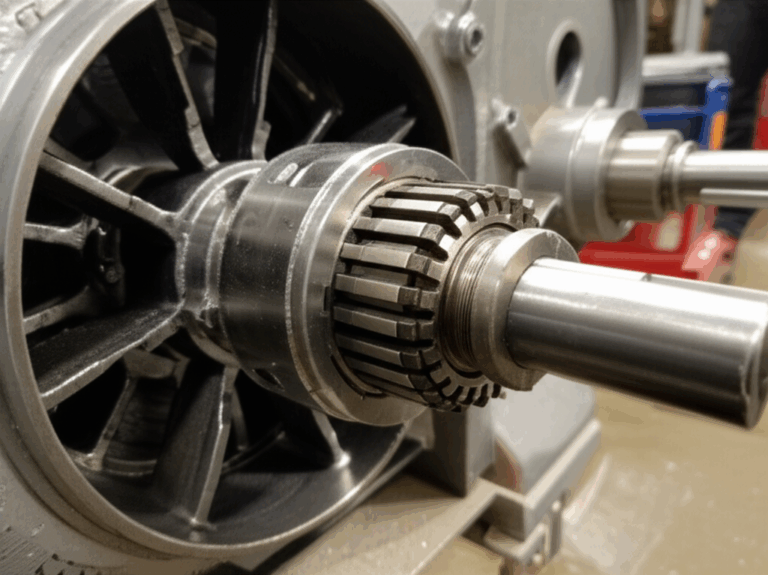
A stator plate is the stationary magnetic core that supports the copper windings in an electromechanical machine. You’ll find it in alternators, generators, and electric motors. While the rotor spins, the stator plate stays put. That’s the defining difference in stator vs rotor.
Physical description:
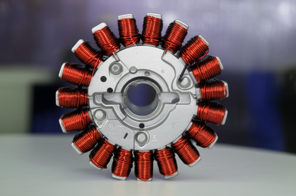
- Geometry. Usually a circular or annular ring in motors and alternators. Some small engines use a semi-circular plate mounted under a flywheel magneto.
- Poles and slots. The core includes poles or slots that hold stator windings. Those copper windings create or capture magnetic fields.
- Laminated construction. Engineers stack thin sheets of silicon steel laminations to build the stator core. Those laminations reduce eddy currents and hysteresis losses which improves efficiency.
- Mounting features. The stator plate mounts to a housing with precise stator dimensions and mounting points to maintain air gap to the rotor.
You might hear adjacent terms like stator coil, stator winding, stator core, stator lamination stack, or stator assembly. In many contexts the “stator plate” refers to the laminated core that the windings sit on. In motorcycle charging systems the term “stator plate” often describes the entire stationary assembly mounted under the flywheel including coils, potting, and harness.
If you need a deep-dive on core geometry and materials see this overview of stator core lamination.
How a Stator Plate Works in Generators and Motors
Let’s simplify the physics. Faraday’s Law of Induction says a changing magnetic field induces a voltage in a conductor. Lenz’s Law says the induced current opposes the change that created it. Everything the stator plate does dances on this stage.
- In alternators and generators. The rotor carries permanent magnets or field windings. As it rotates, the magnetic field sweeps past the stator windings. That changing field induces an AC voltage in the stator coils. Your voltage regulator and rectifier bridge then shape it into usable DC for a battery in a vehicle electrical system. This is how a car alternator stator or motorcycle stator charges a battery through a voltage regulator rectifier.
- In electric motors. The stator plate carries windings that you energize. Controlled currents create a rotating magnetic field. This field interacts with the rotor to produce torque. That’s the core of torque production and power generation in AC induction motors, synchronous motors, BLDC motors, servo motors, and stepper motors.
Analogy. Think of eddy currents like whirlpools in a river. The magnetic field changes with time and frequency which tries to stir circular currents in the solid core. Laminations break the flow into thin sheets which keeps those whirlpools small. Less useless swirl means less heat and higher motor efficiency.
Key variants you’ll encounter:
- Permanent magnet alternator vs wound field alternator. PM alternators use rotor magnets. Wound field alternators energize a rotor field coil. The stator does the same job in both cases. The control strategy and rectifier differ.
- Synchronous motor stator vs asynchronous motor stator. Both use a laminated stator with windings. The current waveforms and rotor design differ which changes slot geometry and insulation needs.
- Single-phase stator vs three-phase stator. Phase count changes slot count, coil grouping, and magneto motive force (MMF) distribution.
Inside the Stator Plate: Components and Construction
Engineers build stator plates to guide magnetic flux efficiently and carry current safely.
- Stator core. A stack of silicon steel laminations forms the magnetic path. The lamination stack reduces eddy current losses. You’ll see grades like M15 to M47 with thickness around 0.35 mm to 0.65 mm for many applications. Thinner sheets help at higher frequencies.
- Slots and slot insulation. Slots hold the copper windings. Slot insulation shields copper from the steel core. Materials include slot liners and wedges with electrical insulation ratings per IEC or NEMA.
- Stator windings. Copper wire wrapped around poles or layered in slots. Winding patterns vary by topology. Hairpin windings boost slot fill factor in EV traction motors which raises power density and improves heat dissipation.
- Insulation system. Varnish coating or epoxy potting protects windings from vibration, moisture, and partial discharge. A robust insulation class improves lifespan especially in high temperature or high voltage stress environments.
- Housing and mounting. The stator plate mounts to an engine case, motor frame, or generator housing. Tight tolerances keep the air gap uniform which stabilizes torque and reduces acoustic noise.
For an overview of electrical steel used in these cores review electrical steel laminations.
Materials and Lamination Choices That Drive Performance
Here’s where design meets physics. The stator plate material and lamination design directly set losses, temperature rise, and efficiency. Clarity beats complexity so let’s break it down.
Core losses have two main parts:
- Hysteresis loss. Energy needed to flip magnetic domains each cycle. It scales with frequency and depends on the steel’s coercivity which is the resistance to being demagnetized.
- Eddy current loss. Currents induced in the core that turn into heat. It grows with the square of lamination thickness and with frequency.
Material choices:
- Silicon steels (M-grades). These are the workhorses. You’ll see M15 to M47 grades and others. Silicon raises resistivity which cuts eddy currents. It also shapes the B-H curve which affects magnetization behavior. Non-oriented silicon steel fits motors and generators where flux rotates. Grain-oriented steels target transformers with one dominant flux direction.
- CRGO vs CRNGO. Cold rolled grain oriented (CRGO) excels in transformers. Cold rolled non-grain oriented (CRNGO) suits motors and alternators where flux rotates with the rotor. Motors need CRNGO for balanced properties in all directions.
- High-silicon or low-loss grades. Higher silicon content and optimized processing reduce core loss. These grades cost more and reward you with lower heat.
- Cobalt alloys. You may choose cobalt-iron alloys for high-power-density or high-temperature aerospace or defense applications. They carry higher cost yet deliver excellent saturation flux density which shrinks core mass.
- Specialty steels for high frequency. Thin-gauge materials and amorphous or nanocrystalline alloys can shine at very high frequencies. You pay a premium and gain lower eddy current losses.
Lamination thickness:
- Thinner laminations reduce eddy currents which improves efficiency especially at high frequency. You see thicknesses in the 0.35 mm to 0.65 mm range for many industrial motors. Some high-frequency machines run thinner.
- Insulation between laminations breaks conductive paths. Coatings matter. They must survive punching or laser cutting without flaking.
Design knobs that move performance:
- Slot fill factor. More copper in the slot means lower copper loss and higher power density. Hairpin windings improve fill and thermal path.
- Stator lamination stack height and pole count. These control flux density and torque ripple. More poles can improve low-speed torque. They can increase frequency at a given mechanical speed which raises core losses if you don’t manage lamination thickness and material.
- Magnetic permeability. Picture it like a sponge soaking up water. High permeability lets magnetic field lines flow easily which lowers magnetizing current. Balance it with saturation limits.
If you need a primer on grades and sourcing see this guide to silicon steel laminations.
Standards to consult when you write specs:
- IEC 60034 for rotating electrical machines
- IEC 60404 series for magnetic materials testing
- NEMA MG 1 for motors and generators
- ASTM standards for electrical steel sheet and coating types
Manufacturing and Assembly Processes That Shape Outcomes
The stator plate earns or loses efficiency on the factory floor. Your process choice affects lamination edge burrs, insulation integrity, and residual stress in the steel. Here’s a balanced view.
Blanking and cutting:
- Progressive stamping. Ideal for high-volume production with repeatability and low cost per piece. It demands good die design and maintenance to keep burrs low and lamination edges clean.
- Laser cutting. Great for prototypes, small runs, or complex geometries. It avoids tooling cost. Heat-affected zones can raise local loss if not controlled.
- Wire EDM and waterjet. Useful for special geometries or material trials. Slower and more expensive but very precise.
Stacking and bonding:
- Interlocking laminations. Think LEGO bricks snapping together. Tabs lock the stack without external fasteners. It’s fast and avoids welding heat. It may change local magnetic paths if tabs sit in high-flux areas.
- Riveting or cleating. Simple and reliable. It adds mechanical hardware and potential local stress.
- Welding. Strong mechanical joints but heat can degrade magnetic properties. Keep welds short and away from high-flux paths.
- Adhesive bonding or core bonding varnish. Provides uniform stiffness and damping which reduces audible noise and vibration. It also seals against moisture.
Coil insertion and impregnation:
- Random wound vs form wound vs hairpin. Choose based on slot geometry, voltage stress, and fill factor goals.
- Varnish coating stator. Vacuum pressure impregnation (VPI) pulls varnish into the windings for moisture resistance and better heat transfer.
- Epoxy potting stator. Common in motorcycle stators and small engine alternators. Potting encapsulates coils and improves vibration robustness. It can limit repairability.
Quality gates:
- Dimensional checks on OD, ID, and stack height to control air gap.
- Electrical tests for stator resistance and phase balance.
- Insulation resistance and hipot tests per IEC or IEEE guidance.
- Core loss testing on lamination material batches.
For a broad look at processes and how they tie together explore motor core laminations.
Where You’ll Find Stator Plates: Applications and Variations
You’ll see stator plates across the automotive industry, industrial machinery, renewable energy, and marine industry. A few common cases:
- Vehicle alternators. The alternator stator supplies AC that the rectifier turns into DC. The voltage regulator holds system voltage. Symptoms of a bad stator or alternator include a “battery” light, dimming lights, or a car battery not charging. Brands like Bosch or Denso supply many OEM alternators.
- Motorcycle and ATV charging systems. A flywheel magneto spins over a potted stator. The rectifier regulator controls charging. Motorcycle no charge issues often trace back to stator output voltage dropping under load, shorted stator coils, or open circuit stator windings. ATV charging system problems show similar signs.
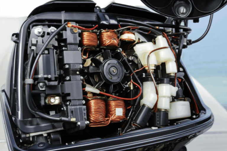
- Outboard and marine engine stators. Marine stators face moisture and corrosion so potting, sealants, and quality slot insulation matter.
- Electric motors. Induction motor stators, synchronous motor stators, and brushless DC motor stators power fans, pumps, conveyors, machine tools, and EVs. Servo motor stators and stepper motor stators deliver precise motion control.
- Wind turbine generator stators. Power conversion happens at scale. Thermal management and insulation life drive total cost of ownership.
- Home generator stators and industrial generator stators. Design targets vary from low-cost standby units to high-duty cycle industrial power.
When you compare stator vs armature or field coils vs stator coils remember vocabulary shifts by machine type. In DC machines, the armature rotates. In AC motors and alternators the stator holds the armature windings in many textbooks. Use context to reduce confusion.
Troubleshooting and Reliability: Symptoms, Testing, and Failure Modes
A bad stator can sideline a production line or leave a rider stranded. Here’s a compact guide to find trouble fast.
Common symptoms:
- Alternators and generators. Dimming lights, weak battery, warning lights, difficulty starting, or complete electrical failure. You may smell burning insulation from overheating windings.
- Electric motors. Reduced torque, motor not starting, tripping circuit breakers, excess heat, or unusual noise.
- Thermal signals. Overheating stator coils cause varnish odor and discoloration.
Frequent failure modes:
- Overheating. The leading cause in many failure studies. Excessive load, poor cooling, high ambient temperatures, or shorted turns drive temperature rise.
- Insulation breakdown. Aging, moisture ingress, or voltage spikes degrade insulation. Partial discharge at high voltage can accelerate damage.
- Shorted stator. Turn-to-turn shorts or phase-to-phase faults reduce output and raise localized heating.
- Open circuit stator. A broken lead or coil results in loss of phase and rough operation.
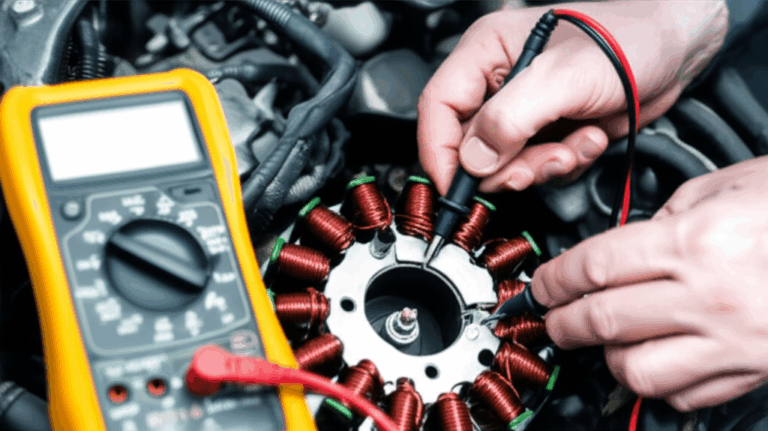
Testing a stator:
- Basic resistance checks. Use a multimeter to measure stator resistance phase-to-phase and compare across phases. Look for balance.
- Continuity to ground. Check for shorts to the core. Any continuity to the lamination stack signals insulation failure.
- Insulation resistance testing. A megohmmeter test at the appropriate voltage gives a reading on moisture and insulation health.
- AC output testing on PM magnetos. With the engine at known RPM measure stator output voltage before the regulator. Compare to service manual specs or wiring diagram stator references.
- Advanced tests. Surge tests and partial discharge tests appear in higher voltage settings. Follow IEEE and IEC practices for safety.
Maintenance tips:
- Keep cooling paths clean for fan cooled stators. If the design uses liquid cooled stators maintain coolant quality and flow.
- Avoid overloads and voltage spikes. Use proper fusing and surge suppression.
- Inspect connectors and harnesses. Many charging system components fail at connectors not just in the coils.
A note on lifespan:
- Automotive alternators often run 7 to 10 years in normal service.
- Industrial motors can reach decades with proper preventative maintenance.
- Condition monitoring for temperature and insulation resistance predicts failure and reduces downtime.
Sizing, Cooling, and Efficiency Factors You Can’t Ignore
You don’t pick a stator plate in isolation. You size it with your rotor, power electronics, and duty cycle.
- Rotor pairing. Stator vs rotor design must match. Induction machines depend on a carefully tuned air gap and slot geometry. PM machines depend on magnet grade and placement. If you want a primer on the rotor side scan this summary on rotor core lamination.
- Frequency and pole count. Pole count defines electrical frequency for a given mechanical RPM. Higher frequency raises core loss which pushes you toward thinner laminations and low-loss materials.
- Cooling. You can go with fan cooled stators or liquid cooled stators. EV traction motors rely on direct oil cooling or jacket cooling to keep temperatures in check. Better cooling allows higher current density and higher continuous power output.
- Slot fill and thermal path. Higher slot fill factor reduces copper loss. It can make winding insertion harder. Plan for production and repair.
- Efficiency targets. A single percentage point in motor efficiency can translate to major energy savings in industrial settings or extended range in electric vehicles. That’s why you’ll see optimized winding insulation systems, improved stator current density balancing, and advanced varnish impregnation techniques.
- Noise and vibration. Bonded core laminations and balanced magnetic loading reduce acoustic noise. Winding choices can shape torque ripple.
- Standards and test plans. IEC 60034 and IEEE test methods bring apples-to-apples numbers for core loss and efficiency.
Which Option Fits Your Application? A Quick Match Guide
- High-frequency machines. Go thinner on laminations. Use low-loss silicon steel or advanced alloys. Keep cutting processes gentle on edges to avoid extra loss.
- EV traction motors. Focus on low-loss CRNGO silicon steel with optimized hairpin windings and robust liquid cooling. Pay attention to slot insulation and partial discharge resistance because inverter PWM puts stress on windings.
- Industrial induction motors. Non-oriented silicon steel with balanced cost and performance. Progressive stamping shines in volume. VPI varnish improves longevity.
- Small engine magnetos for motorcycles and ATVs. Permanent magnet alternator stators with epoxy potting stand up to vibration and oil mist. The rectifier regulator handles AC to DC conversion. Watch for overheating around exhaust paths.
- Wind turbine generators. Design for thermal stability and long life. Moisture protection and insulation class upgrades matter.
- Servo and robotics applications. High torque density solutions benefit from cobalt alloys in select cases. Count the cost carefully and weigh manufacturing complexity.
Be honest about constraints:
- Laser cutting delivers speed and flexibility for prototypes. Stamping wins on volume cost if your geometry suits it.
- Adhesive bonding reduces noise and improves structural damping. It adds process steps and cure time.
- CRGO shines in transformers where flux flows in one direction. CRNGO fits rotating machines.
Cost, Sourcing, and Quality: What Procurement Managers Should Watch
Choices that look small on paper show up in your warranty budget later. Here’s the short list to manage.
- Part cost vs total cost. Stator replacement cost for a motorcycle sits around the low hundreds for parts. Alternators for cars can run higher because you often replace the entire unit. A failed industrial motor stator can cost thousands to rewind. Downtime can cost much more than the part.
- OEM stator vs aftermarket stator vs stator rebuild kit. OEM parts bring fit and performance consistency with a price premium. Aftermarket stators can deliver savings if the supplier proves material grade, slot insulation quality, and winding integrity. Rebuild kits can work when you have skilled technicians and known-good cores.
- Quality control on laminations. Demand material certificates. Verify lamination grade, thickness, coating class, and core loss values. Consider PPAP or similar documentation for automotive programs.
- Inspection and incoming tests. Randomly sample stack height, OD, ID, burr height, and flatness. Verify insulation resistance on sample stator assemblies. Confirm that varnish or epoxy meets flame and thermal ratings as specified.
- Standards alignment. Specify IEC, IEEE, and NEMA references. Clarify insulation class and duty cycles.
If you’re exploring options across categories, this single-page hub on core lamination stacks can help you compare families at a glance.
Your Engineering Takeaway
Let’s pull it together with the Expert Consultant model.
Problem
- You need a stator plate that delivers efficiency, reliability, and cost control in your alternator, generator, or electric motor.
- Material and process choices drive eddy current loss, heat dissipation, torque production, and lifespan.
Explain
- A stator plate is the stationary laminated core with slots for copper windings. It channels magnetic flux and either creates a rotating magnetic field in motors or captures it in generators.
- Core losses split into hysteresis and eddy current losses. Thinner, insulated laminations and low-loss silicon steel grades reduce those losses.
- Cooling, slot fill factor, and insulation systems shape performance just as much as material choice.
Guide
- Use CRNGO silicon steel for most motors. Consider cobalt alloys only when you need extreme power density and accept higher cost.
- Choose progressive stamping for volume and laser cutting for prototyping or complex small runs.
- Bonded and interlocked stacks give robust cores. Keep welds minimal and out of high-flux zones.
- For high-frequency machines pick thinner laminations. For harsh vibration environments consider epoxy potting.
Empower: Actionable next steps
- Define your electrical frequency, duty cycle, and efficiency target. That pins down lamination thickness and grade.
- Specify lamination material with acceptable M-grades and core loss limits at your operating frequency. Reference IEC 60404 test methods.
- Lock the winding approach and slot fill factor early because they set copper loss and cooling paths.
- Plan your cooling strategy. Fan cooled for general duty or liquid cooled for high-power density.
- Build a test plan. Include stator resistance matching, insulation resistance, hipot as needed, and core loss checks on incoming material.
- When you brief suppliers share your rotor details, air gap, frequency, and duty cycle. Ask for past performance in similar machines. For background see this overview of electrical steel laminations.
Final thought. The stator plate looks simple at first glance. It’s a stack of steel with slots. Yet it decides whether your machine sips energy or wastes it as heat. Design it with care, validate it with the right tests, and partner with a lamination supplier who can hit your specifications without cutting corners. That’s how you move from “good enough” to genuinely efficient machines.
If you need a quick refresher on how stators and rotors fit together in different machine types take five minutes to skim motor core laminations. It’s a fast way to align your team before you finalize the spec.