What is a Stator on a Motorcycle? Your Complete Guide to This Essential Power Component
Every engineer who has chased a stubborn charging fault knows the feeling. The battery looks fine. The wiring checks out. Yet the bike still dies on the ride home. Nine times out of ten the trail leads to the stator. If you design or source these components you face a different challenge. You balance efficiency, thermal headroom, and manufacturability while holding the line on cost. Either way you need a clear picture of what a motorcycle stator is, how it works, why it fails, and how lamination choices make or break performance and life.
That is what this guide delivers. We speak to the full audience. Riders who need practical diagnostics. Engineers and procurement managers who want material and process clarity. We start with the problem. Then we explain the fundamentals. We guide you through options. Finally we empower you with checklists and next steps you can take today.
Table of Contents
I. Introduction: The Heart of Your Motorcycle’s Electrical System
- What is a stator? The stator is the stationary set of copper windings around an iron core inside your engine. It works with a spinning rotor packed with magnets to generate electricity. Engineers call this assembly a permanent magnet generator or PMG. Many riders call the whole thing a magneto. Strictly speaking the magneto also includes a self-contained ignition generator. On modern motorcycles the stator is a generator. It feeds AC power to a rectifier and a voltage regulator. The reg/rec converts AC to DC and holds voltage within safe limits.
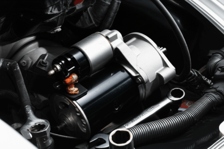
- Why is it important? The stator charges the battery and powers everything on the bike. Headlights, tail lights, EFI, ECU, CDI on carbureted machines, spark plugs, dashboard, ABS, heated grips, and the starter motor’s recharge after cranking. If the stator stops pulling its weight the battery drains. Then the engine misfires or dies. At night your lights dim. Bad day.
- Where is it? Typically behind a side engine cover. It often runs in engine oil for cooling. Some designs mount it dry. You will see a round flywheel or rotor on the crankshaft side and the stator bolted to the case.
Quick definition you can use in a design brief A motorcycle stator is a laminated iron core wound with copper coils that, when exposed to a rotating magnetic field from a flywheel, generates AC power for conversion to regulated DC. It sits inside the engine and forms the core of the charging system.
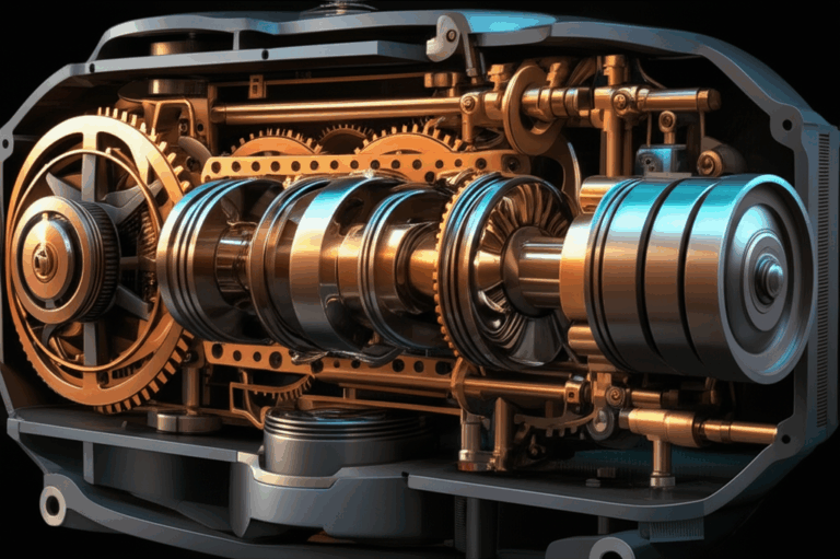
II. How a Motorcycle Stator Works: The Science of On-Board Power Generation
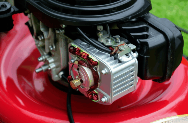
Stator components
- Core: A stack of thin electrical steel laminations with slots. The stack provides a low-reluctance path for magnetic flux while keeping eddy currents low.
- Windings: Copper wire wound into poles or teeth. Engineers care about conductor fill, slot geometry, and thermal class of insulation.
- Leads: Stator output wires typically three yellow wires on three-phase PMGs.
Role of the flywheel and magnets
- Rotating magnets on the flywheel attach to the crankshaft. As the engine turns so does the rotor.
- Stationary coils remain fixed. The rotor sweeps magnetic flux past the teeth of the stator.
Electromagnetic induction explained
Faraday’s law in plain English. A changing magnetic field induces voltage in a conductor. The rotor magnets swing past the stator teeth which changes the flux in the iron. That changing flux induces an AC current in the windings. Engine RPM and stator output rise together. Double the speed and you roughly double the generated voltage at open circuit.
From AC to DC: rectifier and regulator
The stator makes AC. Your battery and electronics need DC. The rectifier converts AC to DC with diodes or MOSFET bridges. The voltage regulator holds system voltage near a setpoint which is usually 14.0 to 14.6 V for 12 V systems. Two common regulator types show up on motorcycles.
- Shunt regulators dump excess power as heat when the bike draws less than the stator can produce. Many bikes use MOSFET shunt units from brands like Shindengen since MOSFETs run cooler and switch faster than old silicon diodes.
- Series regulators restrict current from the stator under low load conditions which reduces heating in the stator. They cost more yet extend stator life in high-heat applications.
III. The Stator’s Crucial Role in the Motorcycle Charging System
Your charging system is simple at the block level.
- Stator and rotor generate AC. This is the alternator motorcycle owners talk about.
- Rectifier and voltage regulator convert and control. Engineers often bundle them as a reg/rec.
- Battery stores energy and stabilizes voltage for cranking and transient loads.
- Wiring harness, fuses, and relays distribute power.
Powering on-board electronics
Once converted to DC the system powers:
- Headlights and tail lights
- EFI injectors and fuel pump
- ECU or CDI ignition
- Sensors including crankshaft position sensor and pickup coil on some stators
- ABS, dashboard, and accessories such as heated grips and auxiliary LED lights
Charging and maintaining the battery
The stator must supply enough current to cover electrical load and charge the battery. Typical stator amperage on mid-size bikes ranges from 15 to 40 A at cruising speed. Big touring bikes can exceed 50 A. Undercharging leads to sulfation on lead-acid batteries. Overcharging cooks electrolyte and swells lithium packs. A stable reg/rec protects both.
Synergy matters
Stator vs rectifier vs regulator is not a versus fight. They work as a team. A weak reg/rec forces the stator to run hot. A shorted battery strains the regulator. A corroded ground raises system voltage drop. Design and troubleshooting should treat the charging system as a whole.
IV. Symptoms of a Failing Motorcycle Stator: Early Warning Signs
Electrical system issues
- Battery not charging motorcycle. You ride to work then discover a dead battery. Most common symptom.
- Dimming or flickering headlights, taillights, or dash lights. Bright at idle then dim when you rev or vice versa.
- Engine misfires, stalling, or poor performance. EFI gets noisy DC or low voltage. CDI loses spark at higher RPM.
- Difficulty starting the motorcycle. The starter motor pulls the battery down and the battery never recovers.
Physical and sensory signs
- Burnt electrical smell around the side cover. That often means heat damage to windings or insulation breakdown.
- Discolored, melted, or brittle wires or connectors near the stator or reg/rec. Look for browned plastics or cracked insulation.
- Unusual whining or growling noises. Less common but possible if the rotor rubs or bearings fail and the rotor kisses the stator.
V. Common Causes of Stator Failure
- Overheating. The number one killer. High engine RPM and high accessory load drive copper and core temperatures up. A failing shunt regulator makes it worse because it forces the stator to deliver full current nearly all the time.
- Insulation breakdown. Age, heat, vibration, and oil chemical attack degrade varnish and slot insulation.
- Shorted stator coil or open circuit stator. Thermal cycling cracks solder joints or breaks leads. A nicked wire in a slot shorts to the core and burns a phase.
- Oil contamination or sludge in oil-cooled stator cavities. Wrong oil can harm varnish on some designs. Dirty oil slows heat transfer.
- Physical damage. Impact during service, rotor contact from a loose flywheel, or a failed gasket that lets coolant or debris in.
- Grounding issues on the motorcycle. A poor frame ground raises currents in strange places. The stator can overheat while the reg/rec fights voltage drop.
- Charging system failure upstream or downstream. A dying battery draws heavy current and stays undercharged which stresses the stator. Overcharging motorcycle battery conditions from a faulty regulator overheat windings and boil batteries.
Design note for engineers Thermal headroom defines stator lifespan. If your steady-state copper temperature sits near the insulation class limit you will see early failures. Derate for high ambient conditions. Oil-bathed stators often get better heat rejection than dry stators. Liquid-cooled alternators exist on a few models yet most bikes rely on oil splashing and conduction.
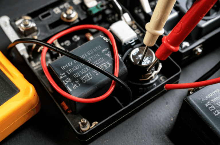
VI. How to Test a Motorcycle Stator: DIY Diagnostic Steps
Tools needed
- Digital multimeter. Use a quality true RMS meter if you can.
- Service manual. It lists stator resistance test values and stator test values for AC voltage output.
- Backprobe pins, small picks, and contact cleaner.
- Visual inspection kit. Flashlight and mirror.
Step-by-step testing procedure
- Visual inspection
- Remove the stator cover if needed or inspect connectors and grommets first. Look for burnt stator windings, melted plugs, oil leaks at the stator cover gasket, and chafed stator output wires.
- Check the rectifier connection to stator. Three yellow wires enter the reg/rec on most three phase stator motorcycle systems. Inspect pins for corrosion.
- Inspect the regulator connection to battery and grounds. Clean and tighten. Confirm fuses and relays are healthy.
- Resistance test (ohm reading)
- With the engine off and the stator unplugged from the reg/rec measure resistance phase to phase. Example for three-phase stators: measure A-B, B-C, and C-A. You want continuity and similar values on all pairs. Typical numbers are very low 0.1 to 1.0 Ohm depending on design. Refer to your stator resistance chart in the manual for exact values.
- Perform a continuity test stator to confirm no open circuit stator. Any infinite reading phase to phase points to a broken wire or connection.
- Ground fault test
- Measure between each stator lead and engine ground. You should see open circuit or very high resistance. Any measurable continuity indicates a shorted stator coil to the core.
- AC voltage output test
- Leave the stator unplugged from the reg/rec. Start the engine. Measure AC voltage between pairs at idle and at 3 to 5k RPM. You should see roughly 18 to 25 Volt AC per 1,000 RPM per phase though models vary. Consult the manual.
- Readings should be balanced across phases. A low leg points to a partial short or bad winding.
- Voltage drop test procedure on the DC side
- Reconnect the stator to the reg/rec. Start the engine. With the multimeter on DC measure battery voltage at idle and at 3 to 5k RPM with lights on. You want 13.8 to 14.6 Volt DC on most 12 V systems. If you see undercharging or overcharging investigate the reg/rec and grounds.
- To confirm grounds and harness integrity perform a motorcycle voltage drop test. Measure from the reg/rec positive output to the battery positive while the system carries load. Anything over 0.2 Volt hints at a harness issue. Do the same on the ground side.
Interpreting results
- Good stator: low and equal phase-to-phase resistance, no ground faults, strong and balanced AC output that scales with RPM.
- Bad stator: any ground fault, any open phase, any unbalanced AC output. Replace or rewind.
- Good reg/rec: holds DC system voltage in spec across RPM and load. No spikes. MOSFET units often run cooler.
- Bad reg/rec: overcharging or undercharging with a good stator. Replace it before it cooks the new stator.
VII. Stator Replacement: When and How to Address a Failed Component
When to replace
- Replace after conclusive testing. If your stator has a ground fault or a dead phase it is done. If only connectors melted you can replace the plug and re-test.
OEM vs aftermarket stators
- OEM stator vs aftermarket. OEM usually fits perfectly and meets original thermal targets. It costs more. Aftermarket ranges from budget to premium. Quality aftermarket stators from vendors like Rick’s Motorsport Electrics, Electrosport, and Cycle Electric often upgrade varnish, slot insulation, and lead wires. They can include a stator repair kit or improved grommets. Choose carefully. Ask for test data and copper fill specs. Warranty matters.
Replacement process overview
- Drain oil if the stator resides in an oil bath.
- Remove the engine cover. Keep track of bolt lengths and dowels. Replace the stator cover gasket.
- Unbolt the stator. Route the new harness along factory clamps. Torque bolts to spec. Clean mating surfaces. Use the correct sealant if the manual calls for it.
- Refill with the correct engine oil. Many riders ask what oil for stator. The answer is simple. Use the factory oil grade and spec. It protects the engine and carries heat away from the stator on oil-cooled designs.
DIY vs professional
- Some bikes make this job easy. Others require exhaust or swingarm removal. If you do not own a torque wrench or a rotor puller or you do not feel comfortable resealing the case use a shop.
Cost ranges you can expect
- Parts cost stator: Aftermarket 80 to 300 USD. OEM 200 to 600+ USD depending on brand.
- Labor cost stator replacement: 150 to 450 USD based on 1.5 to 4 hours at common rates.
- Total replacement cost at a shop: 250 to 1,000+ USD. DIY saves labor. It trades time and risk.
Brand notes riders ask about
- Harley-Davidson touring models see heat-related stator failures in stop-and-go traffic. Aftermarket MOSFET reg/recs help.
- Honda VFR and certain Yamaha, Suzuki, Kawasaki, Triumph, and BMW Motorrad models have well-known reg/rec or stator issues in specific years. Check for a stator recall motorcycle bulletin.
- Ducati, Indian Motorcycle, KTM, Aprilia, and Royal Enfield each have models with different alternator configurations. Field coil alternator systems exist on some large-displacement bikes. PMG dominates on most modern machines.
VIII. Maintenance Tips to Prolong Stator Life
- Regular battery and charging system checks. Test resting voltage. Load test the battery. Yuasa publishes good guidance for AGM batteries. Lithium iron phosphate needs specific chargers and a compatible regulator.
- Monitor charging voltage. Install a small voltmeter on the dash. Keep it between 13.8 and 14.6 V at cruise. Over time you will learn your bike’s signature.
- Avoid excessive electrical loads. Heated gear, halogens, and high-wattage accessories add up. LED lights and stator friendly accessories cut load while raising brightness.
- Upgrade weak links. A quality MOSFET reg/rec or a series regulator reduces stator heat. Shindengen units have a strong reputation.
- Keep oil fresh on oil-bathed stators. Fresh oil carries heat away better than sludge.
- Inspect connectors and grounds every season. Clean and re-tension. Replace browned plugs.
- Balance accessory power. Wire direct to the battery via fused relays. Do not piggyback on factory harness lines with unknown current headroom.
IX. Engineering Deep Dive: Laminations, Materials, and Manufacturing Choices That Shape Stator Performance
Problem
Motorcycle stators fail early when thermal design and manufacturing choices do not match the duty cycle. High RPM cruising and low-speed hot traffic put different stress on the core and windings. Eddy currents waste energy as heat in the core. Poor lamination steel or thick laminations raise core loss. Burrs and shorted laminations undo the whole point of stacking insulated sheets. Procurement teams often face a price delta that looks tempting. Then warranty costs wipe out the savings.
Explain
What is really going on inside the core
- Eddy currents: Picture small whirlpools in a river. Changing flux induces circulating currents in the iron. They make heat. Thin, insulated laminations break big whirlpools into tiny ones which reduces loss.
- Hysteresis loss: The material resists changing magnetization. Each cycle burns a little energy. A narrow B-H curve means lower hysteresis. Lower coercivity helps.
- Magnetic permeability: Think of permeability like how easily a sponge soaks up water. Higher permeability draws magnetic flux into the teeth with less magnetizing current.
- Frequency matters: Stator frequency equals poles times RPM divided by 120 for three-phase machines. As frequency rises eddy current loss increases with the square of frequency. That is why lamination thickness matters more on high-revving engines.
Guide
Material considerations
- Non-oriented silicon steels. The workhorse choice. CRNGO (cold-rolled non-grain-oriented) grades provide balanced properties in all directions which suits radial flux machines with multiple pole directions. Look for ASTM A677 or IEC 60404 grade data. Lower core loss grades cost more yet save heat.
- Grain-oriented silicon steel (CRGO). Great for transformers with unidirectional flux. Not a fit for typical radial flux stators due to directional properties and slotting losses.
- High silicon content steels. Improve resistivity which lowers eddy currents. They can embrittle which affects stamping limits.
- Cobalt alloys. Deliver high saturation flux density and high temperature strength. You see them in aerospace or racing where power density and thermal limits justify cost.
- Insulation coatings. Organic or inorganic coatings like C-5, C-6, or phosphate provide interlaminar insulation. Good coatings survive oil, heat, and slot insertion without cracking.
Manufacturing and assembly processes
- Stamping. Best for volume. Tooling cost is high yet part cost is low. Control burr height and edge quality since burrs can short laminations. Post-stamp stress relief annealing helps recover magnetic properties.
- Laser cutting. Ideal for prototypes and complex low-volume geometries. Heat-affected zones can raise loss unless you control parameters and follow with annealing.
- Waterjet. No thermal damage. Edge taper and surface finish need attention.
- Interlocking and bonding. Interlocking laminations work like LEGO bricks. Mechanical tabs lock the stack without welding which preserves magnetic properties. Bonding with adhesives can reduce noise and improve stiffness. Riveting introduces local stress. Welding damages local magnetic properties unless you isolate the weld zone.
- Slot geometry and fill. Tooth width, slot opening, and wedge design affect flux density and leakage. High copper fill raises I2R loss capacity. Beware hot spots near the slot opening.
Oil vs dry stators
- Oil-cooled stator designs allow higher allowable copper loss since oil carries heat away. Pay attention to varnish chemistry. Pick materials that do not soften in hot oil. Seal the harness to prevent wicking.
- Dry stator designs need better convective paths and sometimes rely on housing fins. Material choice shows up quickly in core temperature.
Specifications that matter to procurement
- Core loss at operating frequency and flux density. Ask for watts per kilogram at your use point not just at 50 or 60 Hz.
- Permeability and B-H curve data across temperature.
- Coating class and interlaminar insulation test results.
- Burr height limits, stack factor, and thickness tolerance.
- Post-processing steps like annealing and deburring.
- Traceability and lot-to-lot consistency. ISO 9001 is table stakes. PPAP can help on automotive-grade programs.
Application crossovers
Many modern scooters and e-motorcycles use BLDC motors for traction. Their stators obey the same lamination rules as charging stators. If you work on traction motors you may want to review bldc stator core best practices and material options.
Where to learn more or benchmark options
- For a broad view of material and stack options review electrical steel laminations to understand coatings, grades, and thickness ranges.
- If you need a component-level view of generator cores explore stator core lamination and rotor core lamination to see slot patterns and stack construction strategies.
- For an overview of how manufacturers integrate these choices into finished components check motor core laminations to see stack methods and assembly options.
Which Application Is This For? Matching Solutions to Your Use Case
- Three phase stator motorcycle with PMG. This is the most common charging setup on mid to large bikes. Choose non-oriented silicon steel with a high temperature insulation coating. Target low loss at the electrical frequency seen at cruise RPM. Use a MOSFET or series regulator if the bike sees long highway runs and low accessory load. It keeps stator heat down.
- Single phase stator motorcycle. Common on small bikes, dirt bikes, and older scooters. Lower output and simpler wiring. The same lamination rules apply. Pay extra attention to pickup coil stator integration and ignition timing stator features if the pickup resides on the same plate.
- Field coil alternator. Some big bikes and cruisers use automotive-style alternators. Instead of permanent magnets you excite a field coil. The rotor is an electromagnet. It lets the regulator control field current which reduces stator heating at low load. The tradeoff is complexity and packaging.
- High-load accessory builds. Touring bikes with heated gear, extra lights, and audio need margin. Consider a stator with higher slot fill and improved cooling. Match it with a robust reg/rec and heavy-gauge wiring harness upgrades.
- Off-road and dirt bike stator. These often blend ignition generation for CDI with lighting coils. Vibration and contamination drive design choices. Potting and robust strain relief become more important than raw efficiency.
Practical design targets and rules of thumb
- Aim for lamination thickness between 0.2 and 0.35 mm for high RPM PMG stators. Thinner reduces eddy loss at the cost of stack factor and manufacturing complexity.
- Keep flux density in teeth below saturation at peak RPM and voltage. A little margin prevents overheating in desert heat or traffic.
- Control burrs to less than 10% of lamination thickness. Lower is better.
- Specify slot liners with thermal class that exceeds the winding varnish. Do not let a liner become the weak link.
- Validate with thermal testing at worst-case RPM and load. Use thermocouples on the end turns and the tooth root.
Real-world considerations for brands and platforms
- Harley-Davidson touring platforms generate serious heat near the primary. Oil circulation patterns matter. Upgraded series regulators reduce stator temperature.
- Sport bikes from Honda, Yamaha, Suzuki, and Kawasaki run high RPM which raises electrical frequency and core loss. Thin laminations and clean slot geometry pay off.
- European bikes from BMW Motorrad, Ducati, Triumph, KTM, and Aprilia vary widely in alternator placement. Some use sophisticated MOSFET reg/rec units from the factory. Check part numbers and thermal ratings.
- Royal Enfield and Indian Motorcycle platforms show a mix of single and three-phase designs. Procurement teams should confirm supplier coating compatibility with the oil package.
Troubleshooting Edge Cases Engineers See
- Rotor vs stator mismatch. Aftermarket rotors with stronger magnets can saturate a stator designed for lower flux. That raises temperature. It also risks overvoltage if the regulator lacks headroom.
- Ground loops. Powder-coated frames and rubber mounts complicate return paths. Confirm bonding straps and star grounds near the reg/rec.
- Connector aging. Heat cycling collapses spring force in terminals. Replace terminals not just housings. It prevents recurring voltage drop.
- EMI vs sensors. Poorly filtered rectifiers can introduce noise on EFI and ECU sensors including the crankshaft position sensor. Good harness layout and shielding help.
Common Questions We Hear
- “Why is my motorcycle battery dead after a ride?” The battery acts as the canary. If the stator or reg/rec undercharges you run on reserve until it goes flat. Test AC output and the regulator next.
- “What are typical stator output voltage numbers?” Expect roughly 18 to 25 VAC per 1,000 RPM per phase at open circuit on many three-phase PMGs. Always check the manual.
- “Magneto vs stator. What is the difference?” A magneto generates power for ignition without a battery. A stator in a PMG generates AC for conversion to DC to charge a battery and run the bike.
- “Can LED lights and stator upgrades fix dimming?” LEDs cut load which gives the stator an easier job. They do not fix a bad stator. They can extend life by lowering heat.
- “Do heated grips and stator loads kill stators?” Not if the system has margin. Large continuous loads raise average stator temperature. They shorten life if you run at the limit.
Entities and components in context at a glance
- Stator, rotor, flywheel, magnets, and crankshaft inside the engine
- Rectifier, voltage regulator, reg/rec module with MOSFET
- Battery from brands like Yuasa
- Wiring harness, fuses, relays, and connectors
- Multimeter for diagnostics with readings in volt, ampere, ohm
- AC generation and DC conversion path sometimes labeled alternating current generator and direct current converter in documents
Procurement Checklist for Stators and Laminations
- Electrical steel grade: core loss at operating frequency and flux. Permeability targets.
- Lamination thickness and coating: verified insulation resistance and chemical compatibility.
- Manufacturing process: stamping with burr control, annealing plan, or laser cut with HAZ management.
- Stack assembly: interlock, bond, rivet. Noise and rigidity targets.
- Winding specification: copper fill factor, insulation class, impregnation varnish, and bake parameters.
- Validation data: temperature rise vs load at defined ambient and oil temps. Endurance tests that reflect real duty cycles.
- Supplier process control: ISO certs, PPAP when needed, traceability. Ask for capability data on critical dimensions.
X. Your Engineering Takeaway
If you only remember one thing remember this. A motorcycle stator is a laminated iron core with copper windings that turns rotor motion into AC power. It lives or dies by heat. Materials, lamination thickness, winding design, and regulator choice set temperature and life.
Key points
- Symptoms that scream charging trouble: draining battery, flickering lights, poor starting, burnt smells, melted plugs.
- Tests that pin it down: phase resistance, ground fault, AC output per phase, and DC charging voltage under load. Use a multimeter and your manual’s stator test values.
- Causes you can prevent: overheating from high loads and weak shunt regulators, bad grounds, dirty oil on oil-cooled stators, and poor connectors.
- Replacement choices: OEM for drop-in confidence. Aftermarket from reputable brands like Rick’s Motorsport Electrics, Electrosport, and Cycle Electric when you need upgrades or better value.
- Design levers for engineers: choose low-loss CRNGO electrical steels, thin laminations, robust coatings, and clean stamping or laser processes. Validate thermal performance at real duty cycles. Do not ignore the reg/rec. A MOSFET or series regulator can save your stator.
- Application fit: three-phase PMGs dominate modern bikes. Single phase shows up on small or older models. Field coil alternators appear on some large platforms. Match materials and cooling to the use case.
Next steps you can take today
- If you are troubleshooting: run the quick tests above. Confirm stator health before throwing parts at the bike. Replace weak connectors and grounds along the way.
- If you are designing or sourcing: align lamination thickness and grade to your electrical frequency and flux. Set burr and coating specs in your drawings. Audit annealing and bonding steps. Validate temperature rise at the worst case. Consider a higher performance regulator if heat margin is thin.
- If you want a deeper look at stack options and material tradeoffs: review motor core laminations and compare slot and stack strategies. For component-level insight see stator core lamination and rotor core lamination. For material background start with electrical steel laminations to weigh grade and coating options. If your program includes traction motors on scooters or EV platforms study bldc stator core guidance to ensure thermal and acoustic performance.
A final word
Clarity beats complexity. When you tame losses in the laminations and you keep the regulator honest you lower temperature. Lower temperature extends insulation life. That puts warranty issues in the rearview and keeps riders rolling.
Sources and standards to consult
- IEC 60034 series for rotating electrical machines
- IEC 60404 and ASTM A677 for electrical steel properties and test methods
- OEM service manuals for stator test values and wiring diagrams
If you want a second opinion or a sanity check on specifications send your lamination stack drawing and duty cycle summary to your supplier’s engineering team. Ask for loss modeling at your frequency and flux targets. You will get a faster quote and a better part.