What is a Stator in a Generator? Understanding Its Core Role in Electricity Generation
You want to know how a generator makes power. You want clear words. You want the big picture. This guide gives it to you. I show you the stator. I show how it works with the rotor. I explain parts, tests, and care. I also share ways to keep your generator safe and strong.
I have worked with engineers and plant teams. I have seen what goes right. I have seen what goes wrong. I know the problem. I know how to fix it. You will walk away with real steps you can use today.
Table of Contents
What you will learn in this guide
- You get the stator definition and the stator function.
- You see how a stator makes AC current generation using Electromagnetic Induction.
- You meet the parts of a stator and the materials for stator windings.
- You learn stator vs rotor and why they need each other.
- You see common stator faults and stator failure symptoms.
- You learn testing a generator stator and how to diagnose stator problems.
- You get a stator replacement guide and tips on stator repair vs replacement.
- You see how good laminations cut stator core losses and boost generator efficiency and stator life.
Problem. Generators fail when the stator gets weak. Agitate. A shutdown hurts your power and your wallet. Solution. Build with strong core laminations and copper windings in generator designs. Keep up smart maintenance and testing.
What is the stator definition in simple words?
The stator is the stationary part of generator machines. It does not spin. It stays fixed inside the housing. That is why we call it the stator. The word comes from “stationary.”
The stator holds the windings or coils. These are the stationary coils generator designers place in slots. The rotor moves near them and makes a changing magnetic field. That change induces Voltage in the stator windings. We call this Electromagnetic Induction. It is the heart of the generator operating principle.
I like simple pictures. Think of a wheel that spins near a fence. The fence stays still. The wheel makes wind. The wind moves across the fence. The fence feels it. The rotor is the wheel. The stator is the fence. The changing wind is the magnetic flux.
How does a stator work to make electricity?
Faraday’s Law of induction says a changing magnetic field makes Voltage in a coil. Lenz’s Law says that the new Current will oppose the change. These rules guide every Generator and Alternator on earth.
Here is how it works. The Rotor spins at some RPM or Revolutions Per Minute. Field Windings on the rotor or permanent magnets create a Magnetic Field. The field cuts across the stator flux lines in the Core. That change in magnetic flux links with the windings. It makes Voltage generation in stator coils. Load flows and the Current in stator windings delivers Power to Output Terminals.
This dance of magnetic flux generator physics gives you AC or Alternating Current. The Frequency of generator output depends on RPM and the number of poles. This is power generation principles in action. You do not see it. Yet you use it every day.
What are the parts of a stator?
You can break the stator into three main parts. Let me walk you through generator components explained in plain talk.
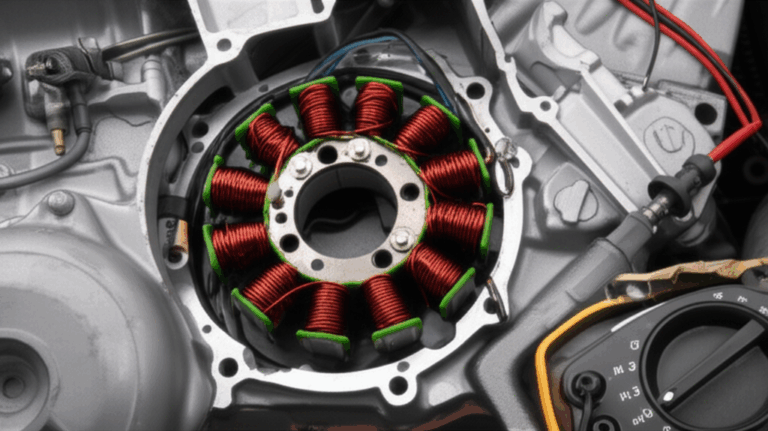
- Stator Core. This is a stack of thin Laminations made of Electrical Steel or Silicon Steel. Builders call this stator lamination construction. The core channels the Magnetic Field and cuts eddy currents in stator and hysteresis losses stator. The core sits inside the Housing or Frame. It gives shape and strength. The core laminations purpose is to guide flux and reduce heat.
- Stator Windings or Coils. These are copper windings in generator slots. Materials for stator windings use Copper Wire with strong Insulation. You see stator end turns where coils bend outside the slots. The stator slot design sets how coils fit and how they cool. The stator winding types can be concentrated winding stator or distributed winding stator. You also see lap winding stator and wave winding stator in some designs.
- Stator Frame Construction. The frame or Housing holds the core and windings. It ties to the Cooling System. It mounts Bearings and aligns the Rotor path. It also keeps dirt out and helps Thermal Management.
In short the stator is the stationary part of generator machines that holds the coils. It stands strong so the moving rotor can do its job.
Stator vs rotor: what is the difference?
The Stator stays fixed. The Rotor spins. That is the clean split. The rotor makes the changing Magnetic Field. The stator turns that change into Electricity.
You will see a rotating field design in most units. The rotor field uses Field Windings with DC or Direct Current from an Exciter. Some machines use a brushless generator stator and a rotating diode bridge on the shaft. Others use slip rings commutator generator parts to feed the rotor. The stator then acts as the armature in AC machines. In many DC Generator designs the stator holds the field and the armature rotates.
Both parts need the right laminations. Stators need tight stator core lamination. Rotors need balanced rotor core lamination. Good steel and good fit raise efficiency and cut noise and heat.
Which types of generators use a stator?
You can find a stator in an Alternator or AC Generator. You can find one in a DC generator too. The details change yet the idea holds.
- Synchronous generator stator. This sits in big Power Plant units. The rotor field locks to grid Frequency. The stator sends Power to the Grid or Electrical Grid. It runs with Turbine drives from Steam, Gas, or Hydroelectric Power.
- Induction generator stator. You see these in Wind Turbine and some small systems. The rotor does not lock to the stator field. It slips a bit. It can feed Renewable Energy to the grid with simple gear.
- Permanent magnet generator stator. These use magnets on the rotor. No field current is needed. You see them in small wind or portable sets.
- Stator in a DC generator. In classic DC machines the stator holds the Field Windings. The armature rotates with a commutator.
You also meet types by phase and service. Single phase generator stator serves small loads. Three phase generator stator serves big loads. You find a small generator stator in a home set. An industrial generator stator lives in a plant with a Diesel Engine or a Turbine. You see an alternator stator in a truck or a ship.
Why does stator design matter for power and efficiency?
Design sets the stakes. The importance of stator design sits in the numbers. When you pick the right steel and the right slot and the right coil you change loss and life.
Stator core losses can be a big slice of total loss. Eddy currents in stator and hysteresis losses stator waste heat. Better Electrical Steel cuts that waste. I like to see high grade electrical steel laminations with grain control. Builders also choose tight silicon steel laminations to trim loss. You win with lower heat and better generator efficiency and stator life.
Stator impedance and stator resistance measurement matter too. They shape voltage drop and heating. The stator magnetic field path in the core must be smooth. The stator slot design shapes leakage and vibration. Good design means better voltage generation in stator and better generator output voltage regulation. It also boosts generator reliability stator performance under shock, dirt, and heat.
Problem. Low grade laminations and poor coils run hot. Agitate. Heat cooks the Insulation. Failures rise and costs jump. Solution. Use quality laminations and sound winding plans with strong Insulation class choices.
How do we test a stator and diagnose problems?
You can spot trouble early. Testing a generator stator saves time and money. Here are the big checks.
- Insulation resistance test stator. This is the classic megohm test. It checks winding Insulation health. It ties to IEEE and IEC guides.
- High potential test stator. People call it the Hipot. It stresses the Insulation to prove it can hold Voltage without flashover.
- Surge test stator. This checks turn to turn strength. It finds weak spots in coils and helps avoid stator coil failure.
- Partial discharge test stator. This looks for tiny sparks inside Insulation. It points to aging before big faults show.
- Open circuit stator test. You run the unit with no load and check Voltage, Current, and Frequency. You can catch balance and core issues.
- Short circuit stator test. You test at low Voltage with blocked rotor in lab or you check short behavior under control. It shows impedance and loss.
How to diagnose stator problems in the field. Look and listen. Use smell and heat maps. Check vibration. Vibration Analysis can find loose stator core or end winding movement. Measure stator resistance. Check stator impedance by phase. Look for stator failure symptoms like low Voltage, high heat, noise, or trips. Use Diagnostics tools and Failure Analysis to plan the fix.
How do cooling and insulation protect the stator?
Heat kills Insulation. The effect of temperature on stator life is huge. Every 10°C up can cut life in half. That is why Thermal Management and the Cooling System matter so much.
Stator cooling methods include air cooling, hydrogen cooling in big units, and direct water cooling in hollow copper conductors. Water can pull 10 times more heat than air in the same space. That lets you pack more Power in the same frame. You also must keep the air or water clean. Dirt and salts attack Insulation.
Pick the right stator insulation class. Class F and Class H are common. Use mica, epoxy, aramid paper, and other layers. Seal end turns. Tie them to stop motion from short circuit forces. Use Quality Control to make sure cure and fit meet the spec. Good Insulation and cooling add years to your machine.
Which winding types do stators use?
You have a few choices. Each one fits a job.
- Concentrated winding stator. Coils sit compact on each tooth. Good for small motors and some permanent magnet generators. Easy to make.
- Distributed winding stator. Coils spread over many slots. Good for smooth Voltage and low ripple in big Alternators.
- Lap winding stator. Many parallel paths. It handles high Current at low Voltage.
- Wave winding stator. Fewer paths. It suits high Voltage at lower Current.
Series wound generator stator, shunt wound generator stator, and compound wound generator stator are terms from DC world. They set how field and armature connect. In AC world we still use the ideas to explain how excitation and load interact.
I look at the job first. Then I pick the winding plan. This simple habit saves time and boosts performance.
How do voltage, current, and frequency stay steady?
You want clean power. So you watch Voltage, Current, and Frequency. You also watch regulation. The generator design considerations and the role of stator in power generation set the limits.
Frequency of generator output depends on RPM and pole count. Keep the prime mover speed steady. Use a governor. Voltage generation in stator depends on field strength and stator impedance. You control it with an exciter and an automatic Voltage regulator. The exciter generator stator may sit on the same shaft or stand alone. It feeds field on the rotor through diodes or slip rings. Good control gives you tight generator output voltage regulation.
What makes a generator work well day to day. A straight core. Solid windings. Clean bearings. Right cooling. Clean Output Terminals and a healthy Circuit Breaker and controls. When these parts work together the power stays steady.
Maintenance choices: stator repair vs replacement
Things wear out. You will face the choice of stator repair vs replacement. Use facts not fear.
Start with a full check. Look at core condition. Measure core loss. Check for hot spots. If the core is sound you can rewind. Stator rewinding cost can be half to two thirds of new. That is a big save for a large unit. If the core is loose or burnt you may need full replacement.
Generator maintenance stator plans should include cleaning, baking, winding resistance checks, and periodic high potential tests. Add partial discharge and surge tests for form wound coils. Keep a log. This is how you raise generator reliability stator performance over the long run.
Problem. Delayed maintenance leads to sudden trips. Agitate. You lose days or weeks and pay rush fees. Solution. Plan the work and work the plan with routine checks.
Size and use: small to industrial stators
Not all stators are the same size. You find a small generator stator in a portable set. It may use simple air cooling. It may be single phase. It can power a home.
You also find an industrial generator stator in a large plant. It can be high voltage generator stator with water cooled bars. It can run at many megawatts in a Nuclear Power or Fossil Fuels Power Plant. You see long end turns and tight bracing. You see strong frame welds. You see smart Thermal Management in every detail.
You also see special cases. A wind turbine stator sits high in a nacelle. A hydroelectric generator stator can be very wide with many slots. A diesel generator stator lives near a Diesel Engine and must handle vibration and soot. Each case has its own needs and its own care.
What is next for stator technology and the environment?
We live in a time of change. Renewable Energy climbs. Grids grow smarter. The future of generator stator technology focuses on better steel, better Insulation, and better cooling.
New Electrical Steel grades cut core loss. Tighter laminations reduce noise. Better resins fight partial discharge. Direct water cooling grows in larger frames. We also see better Diagnostics with online monitors. All of this helps the environmental impact of generator stators. Less loss means less fuel and lower CO2. It helps Wind Turbine and Hydroelectric systems feed clean power too.
You also see smart links to the Grid. Better control helps match load and source. That means safer power for homes and plants. It is good engineering and good for the planet.
A short buying guide on core materials and laminations
If you build or buy a stator you must care about the core. The Core or Stator Core uses Laminations of steel. Thin sheets cut eddy currents and lower heat. The grade and the cut matter.
Pick proven electrical steel laminations with the right silicon mix. Use tight stacks with clean edges. For a stator pick a vendor with solid stator core lamination solutions. Match with precision rotor core lamination sets for balance and low loss. If your design calls for a special silicon content you can review high grade silicon steel laminations for better magnetic path control.
A strong core starts with strong steel. Good steel plus good coils gives you a stator that lasts for years. This is how you meet your power goals with less waste and more uptime.
References
- IEEE Std 43. IEEE Recommended Practice for Testing Insulation Resistance of Rotating Machinery.
- IEEE Std 95. IEEE Recommended Practice for Insulation Testing of AC Electric Machinery.
- IEC 60034. Rotating electrical machines.
- EPRI. Generator Stator Winding Reference Book.
- EASA. Guide to Diagnostic Testing of Rotating Machines.
- P. C. Sen. Principles of Electrical Machines and Power Electronics.
FAQ
Q: Why is the stator fixed and the rotor moving
A: The stator stays fixed for strength and cooling. The rotor spins to make the changing Magnetic Field. This setup is simple and safe.
Q: What causes stator burnout
A: Heat, dirt, vibration, and poor cooling. Overload and short circuit stress also hurt coils. Bad Insulation or loose Laminations can lead to hot spots.
Q: How electricity is generated in a stator
A: A changing Magnetic Field from the rotor cuts across the coils. Faraday’s Law says this makes Voltage. Load flows and you get Current and Power.
Q: What is an armature in a generator
A: In AC machines the armature is the stator. In DC machines the armature is the rotating part with the commutator.
Q: How to build a generator stator the right way
A: Use clean Electrical Steel Laminations. Pack the core tight. Use copper with strong Insulation. Set end turn support. Seal and cure well. Test with surge, Hipot, and partial discharge checks.
Key takeaways
- The stator is the stationary part of generator machines. It holds the coils that make power.
- The rotor makes a changing Magnetic Field. The stator turns that change into Electricity by Electromagnetic Induction.
- Good core Laminations cut stator core losses from eddy currents and hysteresis. This boosts generator efficiency and stator life.
- Use strong Insulation class and smart stator cooling methods. Heat kills coils so keep it cool.
- Test often. Use insulation resistance, high potential, surge, partial discharge, open circuit, and short circuit tests.
- Pick the right stator winding types and slot design for your job. This helps regulation and lowers heat.
- Plan maintenance. Log data. Act early on stator failure symptoms.
- For core quality use trusted suppliers of laminations for stator and rotor. This choice prevents problems and protects your uptime.
Extra detail for learners and pros
Below is a simple table to tie materials, losses, and tests to what you see in the field.
| Topic | What it is | Why it matters |
|---|---|---|
| Stator core material | Electrical Steel with silicon content as needed | Guides flux and reduces loss |
| Laminations | Thin sheets stacked in the Core | Cuts eddy currents and lowers heat |
| Stator winding copper | High purity Copper Wire or hollow bars | Lowers I²R loss and helps cooling |
| Insulation class | Class F or Class H with mica and epoxy | Sets max safe temperature |
| Core losses | Eddy and hysteresis losses | Reduce them to raise efficiency |
| Stator cooling methods | Air, hydrogen, direct water | Protects Insulation and power output |
| Tests | IR, Hipot, Surge, PD, open and short circuit | Finds faults early |
| Control | Exciter and AVR | Keeps Voltage steady |
| Design | Slot design and winding plan | Shapes impedance and performance |
And here is a quick list of related systems you will run into. Use it as a mental map when you review generator components list or when you need understanding generator parts in the plant.
- Alternator in cars and trucks.
- Synchronous Generator in a Power Plant.
- Induction Generator in a Wind Turbine.
- Hydroelectric Power units in dams.
- Diesel Engine driven sets for backup.
- Transformers that step Voltage up or down before the Grid.
- Circuit Breaker gear that protects your Output Terminals.
Along the way you will see Electrical Engineering and Mechanical Engineering teams work as one. They check Vibration Analysis and Thermal Management. They perform Maintenance and Diagnostics with care. They run Quality Control on parts before install. They do Failure Analysis when something trips. This teamwork is what makes a generator work day in and day out.