What Is a Stator Core? Understanding the Essential Heart of Electric Machines
Table of contents
- Introduction: How I Learned to Respect the Stator Core
- The Stator Core in Plain English
- Key Components and Structure
- Laminations
- Stator Slots
- Stator Teeth
- Back Iron (Yoke)
- Stator Windings at a Glance
- The Materials That Make It Work
- Electrical Steel and Silicon Steel
- Grain-Oriented vs Non-Grain-Oriented Steel
- How a Stator Core Works in Motors, Generators, and Transformers
- Why the Stator Core Matters: Efficiency, Performance, and Reliability
- Common Applications You See Every Day
- From Sheet to Machine: How Stator Cores Are Made
- Practical Lessons From the Shop Floor
- Design Choices That Change Everything
- Thermal Management, Noise, and Vibration
- Measuring and Reducing Core Loss
- What’s Next: Materials and Manufacturing Innovations
- Quick Answers to Common Questions
- Conclusion: The Silent Backbone of Electric Machines
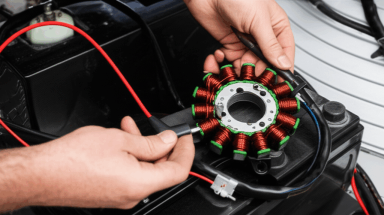
Introduction: How I Learned to Respect the Stator Core
I still remember the first time a “simple” stator core humbled me. I was helping a team diagnose a pump motor that kept overheating. We swapped bearings. We checked the drive. We even replaced the windings. The motor still ran hot. The culprit hid in plain sight. A few laminations in the stator had shorted together due to a tiny scrape during assembly. That short created higher eddy currents. Losses spiked. Heat followed. Once we fixed the lamination stack and re-varnished it, the motor ran cool and quiet.
That day cemented something for me. The stator core looks like a stack of steel rings with slots. It behaves like the brain and backbone of an electric machine. When you get it right, motors and generators sing. When you get it wrong, they whine, they vibrate, and they waste energy.
The Stator Core in Plain English
A stator core is the stationary magnetic circuit in an electric machine. Think electric motors, generators, and even transformers. It guides magnetic flux, provides a low resistance path for that flux, and supports the stator windings mechanically. In motors the stator core helps create a rotating magnetic field. In generators it receives magnetic flux from the rotor and lets the windings “catch” that change as voltage. In transformers the core channels flux from the primary winding to the secondary winding.
I like to call it the machine’s “stationary brain.” It doesn’t move yet it decides how efficiently energy moves. It also carries the structure and helps shed heat. Without a good stator core, you can forget about high efficiency, stable torque, and long life.
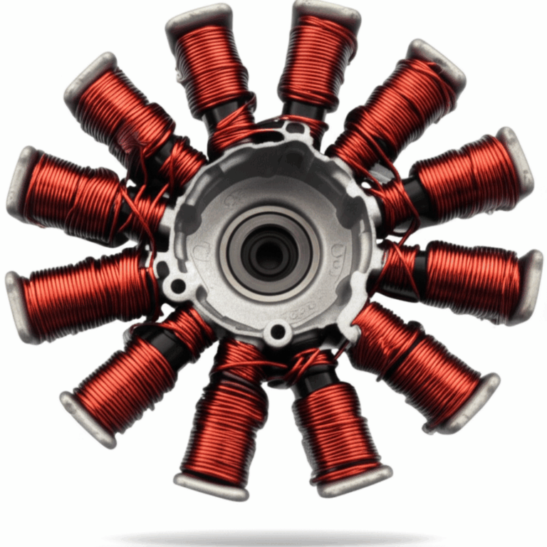
Key Components and Structure
When I break down a stator core for a new engineer, I point out five parts first.
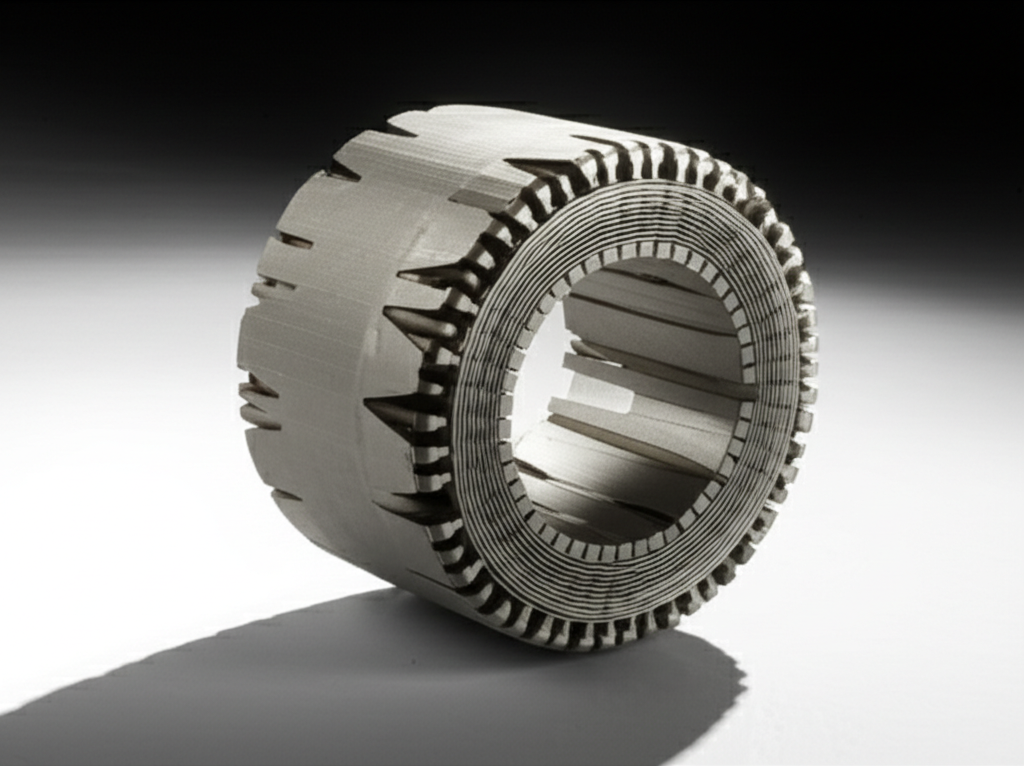
Laminations
The stator core isn’t one big chunk of metal. It’s a stack of thin electrical steel sheets called laminations. We stack them to reduce eddy currents. Eddy currents are loops of current that form in solid metal when the magnetic field changes. They waste energy as heat. Thinner laminations restrict those loops. That’s why a 0.2 mm sheet beats a 0.5 mm sheet for high-frequency applications.
If you want the quick version. Laminations cut eddy currents. Lower eddy currents reduce losses. Lower losses mean a cooler core and better motor efficiency. The details get more interesting. The steel composition, insulation coating between laminations, and the stacking factor all matter. A small stacking error can change the magnetic path length and the flux density which throws performance off more than you’d expect.
If you need a deeper dive into the manufacturing side, this overview of stator core lamination lays out the essentials clearly.
Stator Slots
Slots are the grooves in the laminations that hold the stator windings. Slot shape changes performance. Open slots make winding insertion easy yet can increase noise and cause more flux leakage. Semi-closed and closed slots help with quieter operation and better magnetic performance yet they can be tougher to wind. Slot geometry also affects cogging torque in permanent magnet motors which can make a motor feel jerky at low speeds.
Stator Teeth
Teeth are the parts between the slots. They concentrate magnetic flux and carry it from the back iron into the air gap where the rotor lives. Tooth width and shape impact flux density, iron losses, and torque ripple. In synchronous motors and BLDC designs I tune tooth shape to manage cogging torque and limit acoustic noise.
Back Iron (Yoke)
The back iron forms the outer ring of the laminations. It closes the magnetic circuit and adds mechanical strength. I treat it as the quiet hero. Too thin and it saturates at high load which starves the air gap of flux. Too thick and you add unnecessary mass which raises cost and slows heat flow to the frame.
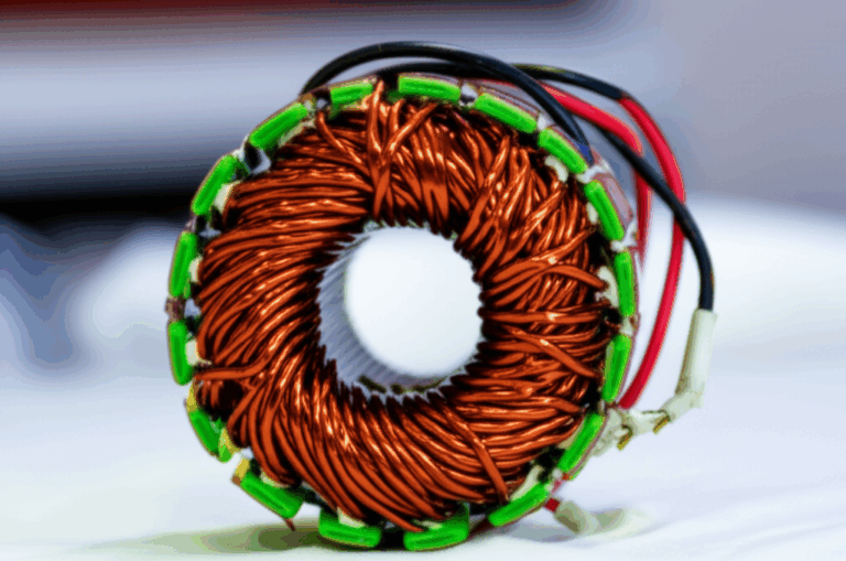
Stator Windings at a Glance
Windings aren’t part of the core material yet they complete the magnetic circuit. Copper or aluminum windings in the slots create the magnetic field in motors or pick it up in generators. Winding layout and slot fill change everything from torque production to heat buildup.
The Materials That Make It Work
Electrical Steel and Silicon Steel
Most stator cores use electrical steel sometimes called silicon steel. The silicon (often between 0.5% and 3.5% in rotating machines) increases resistivity and reduces hysteresis losses. You’ll see terms like “soft magnetic materials” and “magnetic permeability.” Here’s the short of it. The material wants to magnetize easily and reverse magnetization without wasting energy.
I’ve specified grades where the trade-off between cost and performance felt tight. Premium Non-Grain-Oriented Electrical Steel (NGOES) can reduce specific core losses by 15% to 25% at typical flux density. That price jump looks scary until you calculate lifetime energy savings for a motor that runs nonstop in an industrial setting. Then it often pays for itself.
If you’re reviewing your options, this page on electrical steel laminations explains common grades and where they fit.
Grain-Oriented vs Non-Grain-Oriented Steel
- Non-Grain-Oriented (NGOES): It’s isotropic. That means the magnetic properties are similar in all directions. Rotating machines like induction motors, synchronous motors, and BLDC motors use NGOES because the flux rotates.
- Grain-Oriented (GOES): It’s anisotropic. That means it shines in one direction. Transformers love GOES because the flux direction stays fixed through the core limbs. GOES reduces losses in that single direction so it’s perfect for transformer lamination cores.
How a Stator Core Works in Motors, Generators, and Transformers
Motors
Feed AC current to the stator windings and you get a rotating magnetic field. The stator core guides that field into the air gap and across the rotor. The rotor sees that field and responds. In an induction motor the rotor currents appear because of electromagnetic induction. In a synchronous motor or BLDC machine the rotor has permanent magnets or DC-excited windings that lock to the stator’s rotating field. Torque appears as the fields chase alignment. More flux and proper timing mean more torque.
Generators
Flip the story. Spin the rotor so its magnetic field sweeps past the stator windings. That changing flux induces an electromotive force in the windings per Faraday’s Law and Lenz’s Law. The stator core makes the magnetic path efficient so the voltage holds steady and losses stay low.
Transformers
You won’t find a rotor here yet the principle stays the same. The core channels flux from the primary winding to the secondary winding. GOES material shines in this job. The core limits leakage flux and minimizes both hysteresis and eddy losses.
Why the Stator Core Matters: Efficiency, Performance, and Reliability
I’ve never seen a high-efficiency motor with a sloppy core. Core losses often account for 20% to 30% of total losses in a standard AC induction motor. Those losses break down into hysteresis and eddy currents. Pick better electrical steel and you cut hysteresis loss. Use thinner laminations with good insulation and you cut eddy currents. Design the magnetic circuit wisely and you avoid saturation which wastes energy and heats things up.
Here are the benefits you feel in the field:
- Efficiency: Lower core losses mean less heat and higher efficiency. Drives run cooler. Bearings live longer. Energy bills drop.
- Performance: A well-designed stator core produces smooth torque. Torque ripple falls. Power factor improves in many designs because the magnetic circuit behaves predictably.
- Magnetic Circuit Integrity: The core sets the path. Stable flux paths bring stable performance.
- Structural Support: The core takes mechanical loads from winding installation, vibration, and thermal expansion. Good back iron design prevents distortion.
- Heat Management: The core spreads and sheds heat to the frame or cooling system. Better heat paths keep insulation within its class rating.
Common Applications You See Every Day
Once you know what you’re looking at, you see stator cores everywhere:
- Electric vehicles and hybrid electric vehicles use high-efficiency traction motors with dense stator cores. Power density in modern EV traction motors often lands between 3 and 5 kW/kg which demands excellent core materials and cooling.
- Industrial motors run pumps, fans, compressors, and conveyor drives. These include induction motors, synchronous motors, and servo motors.
- Home appliances rely on compact motors in washing machines, refrigerators, and HVAC systems.
- Wind turbines use generator stators to turn mechanical rotation into grid power.
- Alternators in vehicles and distributed generation systems use stator cores to generate steady voltage.
- Transformers in power transmission and electronics use laminated cores to manage flux with low losses.
From Sheet to Machine: How Stator Cores Are Made
I’ll walk you through the path I’ve watched in plants and pilot lines.
1) Stamping or Punching
We cut laminations from electrical steel sheets with precision dies. Laser cutting works for prototypes or specialty shapes. Stamping rules at scale. The edges need care. Burrs increase local flux density and cause hotspots. Die maintenance pays off.
2) Insulation Coating
Each lamination carries a thin insulating coating to block inter-laminar eddy currents. The type and thickness of the coating change with operating temperature and environment.
3) Stacking and Interlocking
We stack laminations into a core. Interlocking tabs or welding points hold stacks together. The stacking factor matters because small changes alter the effective magnetic path. I once saw a 0.5% stacking factor deviation drive a measurable flux density variation which nudged efficiency and torque ripple in a servo motor.
For a broader picture that spans stators and other parts, I like this overview of motor core laminations since it shows how stators and rotors share similar constraints.
4) Annealing
We heat treat the stacks to relieve residual stresses from punching and to restore magnetic properties. Skip this or do it poorly and losses rise.
5) Varnish and Impregnation
We varnish the core to stabilize the stack and enhance insulation. Vacuum pressure impregnation helps in high-performance machines.
6) Winding Insertion
We insert windings into the slots. Slot liners and wedges protect wires and keep them in place. Careful winding geometry controls leakage inductance and heat.
7) Assembly Into Frame and Final Processes
The core fits into a stator frame or housing which has cooling paths and mounting provisions. In high-power designs we integrate cooling jackets or channels near the core back iron to pull heat out quickly.
Practical Lessons From the Shop Floor
Anecdotes stick better than theory, so here are a few lessons I’ve learned the hard way.
- Don’t ignore lamination burrs. I pushed a prototype into testing with only a visual burr check. Iron losses came in 10% higher than the model predicted. A quick pass with better die maintenance and a light deburr brought losses back in line.
- Thin laminations pay off at high frequency. When we dropped lamination thickness from 0.5 mm to 0.2 mm in a high-speed BLDC motor, eddy losses dropped massively at the same flux density. Manufacturing costs went up. The thermal budget thanked us.
- Stator slot shape changes noise and feel. A semi-closed design with skewed slots transformed a jerky low-speed startup into a smooth ramp in a permanent magnet motor. Cogging torque fell and NVH improved.
- Set realistic thermal expectations. Industrial motors often run between 120 C and 180 C in tough duty. Don’t wish that heat away. Build cooling into the core and frame.
Design Choices That Change Everything
Core Geometry and Flux Path
Core geometry sets the magnetic circuit. Tooth width, slot pitch, stack height, and back iron thickness determine flux distribution. Push flux density too high and you hit saturation which explodes losses and wrecks efficiency. Keep it too low and you leave torque on the table. I often aim for a sweet spot around typical operating flux densities like 1.4 to 1.7 Tesla in many industrial motors though exact values depend on the material and application.
Slot and Winding Choices
- Distributed windings vs concentrated windings: Distributed windings can give smoother torque and lower harmonic content. Concentrated windings help with compact designs and can reduce copper length.
- Skew: Skewing slots or rotor bars helps cut cogging torque and torque ripple. It can reduce acoustic noise at the cost of some manufacturing complexity.
- Slot fill factor: High slot fill improves copper utilization and lowers copper loss. It also raises thermal challenges. You need space for cooling and insulation.
Materials and Core Losses
- Electrical steel grade: Premium NGOES reduces hysteresis loss which matters as frequency rises.
- Lamination thickness: Thinner sheets reduce eddy current loss which grows with the square of frequency. High-speed machines benefit from 0.2 to 0.35 mm laminations vs the 0.5 mm that many older designs used.
- Coatings and varnish: Good insulation between laminations stops inter-laminar currents and stabilizes the stack.
Rotor vs Stator
Some engineers ask why stator care seems to take more attention than rotor care. Both matter. The rotor core lamination stack faces its own eddy and hysteresis challenges especially in induction rotors or salient pole synchronous machines. If you want the other half of the story, this primer on rotor core lamination covers how rotor materials and geometry complement stator design.
Thermal Management, Noise, and Vibration
Heat
Heat kills motors slowly. It bakes winding insulation and ages varnish. I work backward from the thermal limit set by insulation class and expected ambient. Then I size cooling paths and contact surfaces so the core can shed heat. The back iron serves as a heat spreader which is why I treat it as both a magnetic and a thermal part.
Noise and Vibration
Noise, vibration, and harshness (NVH) come from electromagnetic forces and mechanical resonances. Slotting and tooth geometry shape the electromagnetic force spectrum. Frame stiffness and damping either amplify or tame it. Skew helps. So does a thicker back iron in some cases. Precision in stacking and assembly reduces uneven forces that create buzz or hum.
Measuring and Reducing Core Loss
You can model core loss with finite element analysis. You should still measure it. I use two approaches.
- Epstein frame or single sheet tester for material samples. These give specific loss numbers at given flux density and frequency.
- Back-to-back tests or calorimetric methods on assembled cores and prototypes. Real geometry sometimes surprises you.
Typical findings from my projects and industry handbooks:
- Core losses often land around 20% to 30% of total losses in standard AC induction motors.
- Upgrading from a mid-grade NGOES to a premium grade can cut core losses by 15% to 25% at the same flux density.
- Halving lamination thickness can drop eddy current loss dramatically which shows up in high-speed designs.
- Small stacking factor deviations cause bigger-than-expected flux swings and inconsistency between units.
- Electrical steel costs often make up about 10% to 15% of the motor’s material cost. You still choose it carefully because it drives lifetime energy cost.
What’s Next: Materials and Manufacturing Innovations
I’ve watched three promising trends gather steam.
- Advanced materials: Amorphous and nanocrystalline alloys can slash losses at certain frequencies. They show up more in transformers today. Some motor designs experiment with them where frequency and efficiency targets justify the cost.
- Soft magnetic composites (SMC): These allow 3D magnetic paths. They enable shapes that laminations can’t achieve easily. SMC parts can reduce assembly steps in some custom actuators and high-frequency machines.
- Additive manufacturing: 3D printing opens the door to integrated cooling channels and novel core geometries. We’re not at mass adoption for large motors yet. Prototypes and special applications show what’s possible.
- Better thermal integration: More motors integrate cooling jackets around the stator back iron. Some designs even add direct cooling channels that sit close to stator teeth to pull heat from the hotspot region fast.
Quick Answers to Common Questions
What is a stator core made of
Mostly electrical steel with a silicon content that improves magnetic properties. The laminations stack up with insulation between sheets to reduce eddy currents. The core interfaces with copper windings and a steel frame.
Why do we use laminated sheets instead of a solid core
Laminations limit eddy currents which waste energy as heat. Thinner sheets yield lower eddy losses at higher frequency.
Does GOES belong in motors
Not usually. GOES behaves best when the flux direction stays fixed which is the case in transformers. Non-grain-oriented steel fits rotating machines better because the flux rotates.
How hot can a stator core get
Industrial and traction motors often see operating temperatures in the 120 C to 180 C range depending on insulation class and cooling. You want to keep the core and windings within their ratings to avoid rapid aging.
What about BLDC motors
BLDC stators follow the same rules. Good laminations, smart slot and tooth geometry, and tight control of cogging torque define how smooth and efficient they feel.
Where do EVs push the envelope
Power density and thermal management. Traction motors target 3 to 5 kW/kg which demands thin laminations, premium steel, and aggressive cooling near the stator back iron and teeth.
How do I pick a lamination supplier
I look at material grade options, coating types, stamping precision, burr control, and annealing capability. A supplier who lives and breathes lamination quality can save you money over a motor’s lifetime. If you’re scanning options at a high level, this site on stator core lamination gives you a sense of the range and typical specs. If your work spans multiple core types, you may also find it helpful to review general motor core laminations or catalog pages so you can compare stacks and coatings across families.
Conclusion: The Silent Backbone of Electric Machines
When someone asks me what a stator core is, I tell them it’s the silent backbone of electric machines. It doesn’t move. It doesn’t sparkle. Yet it shapes the magnetic field that turns electricity into motion or motion into electricity. The core’s laminations fight eddy currents. Its steel composition reduces hysteresis loss. Its geometry focuses flux where it counts.
Get the stator core right and everything else gets easier. Efficiency climbs. Torque smooths out. Heat drops. Reliability improves. That’s true in induction motors, synchronous machines, BLDC motors, alternators, and generators. It’s true in transformer cores too although transformers lean on grain-oriented steel and fixed flux paths.
If you’re designing or buying, pay attention to electrical steel grade, lamination thickness, slot and tooth geometry, and the quality of stacking and annealing. Treat the stator as both a magnetic circuit and a thermal structure. You’ll end up with a cooler, quieter, more efficient machine.
If you want to explore related components while keeping your focus on core quality, these resources are a good next step:
- A deeper look at stator core lamination
- A broad view of motor core laminations
- Materials background on electrical steel laminations
- The complementary view with rotor core lamination
I’ve built and troubleshot enough machines to know this. The stator core may be stationary yet it’s where your machine’s story begins.