What Is a Stator? Understanding the Stationary Heart of Electric Motors and Generators
Introduction: The first time a stator clicked for me
I still remember the smell of warm varnish the first time I walked past a motor rewind shop. Coils baked to a glossy finish sat next to a stack of thin steel sheets. I asked the technician what those sheets were for. He tapped a stack with his knuckles and said, “That’s your stator core. Without it your motor is a pretty paperweight.”
That moment stuck with me. I had learned equations for electromagnetic induction in class. I knew about magnetic flux and EMF. Yet I hadn’t connected those tidy formulas to the physical guts of a machine. The stator became real for me that day. Since then I’ve spent time selecting stator core material, tracing slot and tooth design, troubleshooting winding failures, and even speccing cooling for high power density motors. I’ll share what I learned in plain English so you can build a solid mental model without slogging through a textbook.
Table of Contents
Quick definition: What is a stator
A stator is the stationary part of an electromechanical rotating machine. That includes an electric motor, generator, or alternator. It holds the core and the windings that either create a magnetic field for a rotor to chase or receive induced current when a rotor’s field sweeps past. In short the stator is the fixed half of a duo that turns electrical energy into mechanical energy in motors or mechanical energy into electrical energy in generators.
Why stators matter everywhere
Once you start looking you see stators everywhere. In an electric vehicle traction motor. In a wind turbine generator. In your washing machine. In a hospital’s backup alternator. In drones, industrial pumps, HVAC fans, machine tools, and robotics. Every electric machine that produces torque or power has a stator. The details change across AC motors, DC motors, induction machines, synchronous machines, brushless DC (BLDC) motors, and switched reluctance motors. The stator stays central in all of them.
How a stator drives energy conversion
Electromagnetism 101 and magnetic fields
The stator’s job rides on a simple truth. When current flows through a winding it creates a magnetic field. The field strength depends on current, turns, and the magnetic circuit’s reluctance. Put that winding on a laminated iron core and you guide magnetic flux through a low-reluctance path. That boosts field strength where it matters.
Magnetic fields and motion give you electromotive force. Faraday’s law says a changing magnetic flux induces a voltage. Lenz’s law says the induced current pushes back against the change that created it. Those two laws power every motor and generator you touch.
Motor operation: AC and DC
In an AC motor the stator windings get alternating current across phases. That current creates a rotating magnetic field. The rotor tries to align with it which produces torque. In a three-phase induction motor the stator’s rotating field induces current in the rotor bars, then the resulting rotor field interacts with the stator field to produce torque. In a permanent magnet synchronous motor (PMSM) or a BLDC motor the rotor carries magnets, and the stator’s controlled currents create a field that pulls the rotor along with precise synchronization.
In a DC motor the stator can host the field winding if it’s a wound-field design. The field stays stationary while the armature winding sits on the rotor. That flips the roles. The stator still provides the magnetic field either via a field winding or permanent magnets. Series, shunt, and compound DC motors tune field strength with different field winding connections to current and voltage.
Generator operation: Faraday’s and Lenz’s laws in action
In a generator a turbine or engine spins the rotor inside the stator. The rotor carries a magnetic field. Movement past the stator windings changes the magnetic flux through those coils. Faraday’s law says voltage gets induced in the stator windings which then deliver current to a load. Lenz’s law shows up as a reaction torque on the rotor which you feel as mechanical drag.
Large alternators feed the electric grid with power from hydroelectric plants or steam turbines. Portable generators do the same at smaller scale. The stator in both cases holds the armature winding in AC machines which is where the generated current lives.
Anatomy of a stator: Core parts and materials
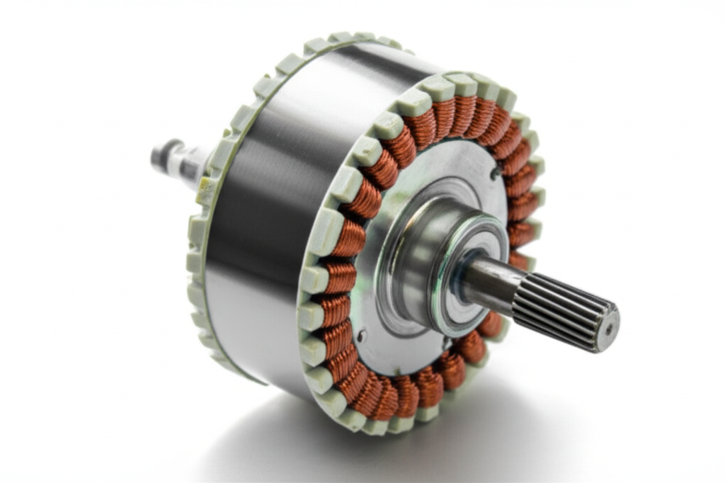
Stator core and laminations
The stator core looks like a ring of steel with slots cut in it. It is not a solid chunk because solid steel would waste energy as heat. Eddy currents swirl in solid metal when fields vary. Laminations stop those currents in their tracks.
We stack thin sheets of silicon steel and insulate each sheet. This lamination stack reduces eddy current and hysteresis losses by a large margin. In motor design work I’ve seen core losses drop by something like 70 to 85 percent when moving from a solid core to a proper laminated core. That is why you’ll hear people talk about silicon steel laminations and grades like CRGO or CRNGO for transformers and machines with specific needs.
- Laminated silicon steel often carries 0.5–4.5% silicon which boosts resistivity and lowers losses.
- Stator laminations get stamped or laser cut into a shape with slots and teeth then stacked and bonded.
- The stacked core provides a low-reluctance path for magnetic flux so your winding current does more useful work.
If you want a clean overview of how these laminations come together in electric machines I’ve found this resource on electrical steel laminations helpful: https://sinolami.com/electrical-steel-laminations/
Slots, teeth, poles, and the magnetic flux path
Those slots and teeth matter. The slots hold the windings. The teeth shape the magnetic field. The number of poles determines the synchronous speed in AC motors for a given frequency. More poles mean lower base speed and higher torque per amp at that speed. Slot and tooth design affects magnetic flux density, cogging torque, ripple, and noise. It also sets the coil layout and the EMF waveform. Get the magnetic circuit analysis right and the machine runs smooth and efficient. Get it wrong and you fight vibration, heating, and losses.
Stator windings and insulation
The windings are copper wire wound into coils. Copper’s high conductivity matters because it keeps I²R losses in check. For stator windings I’ve used enameled copper with varnish impregnation or resin encapsulation. The insulation system must hold against voltage stress, heat, and mechanical motion. Modern insulation systems use polyimide films, mica-based tapes, and high-temperature enamels. Insulation classes set allowable operating temperatures. That might be 130°C, 155°C, 180°C, or even over 200°C in advanced designs.
Hairpin windings show up often in EV traction motors because they boost slot fill factor. Higher fill factor means more copper in the same slot which helps power density. I’ve seen designs that push toward 90% fill with hairpins. That is not trivial to manufacture yet the payoff is real when you need 10–15 kW/kg power density.
Frame, housing, and cooling
The frame holds everything and gives you mounting points. It also acts as a heat path. Stators get hot under load since core losses and copper losses both dump heat into the system. Good thermal management keeps the machine efficient and reliable.
Cooling methods range from simple air cooling with fins to forced air to liquid cooling. In high power density motors like EV traction units I’ve seen direct liquid cooling channels integrated around or through the stator. Dropping stator temperatures by 10–30°C gives you headroom on current density, demagnetization risk in PM machines, and insulation life. You can cram more torque into the same package when you manage heat well.
Stator vs rotor: The partnership that powers everything
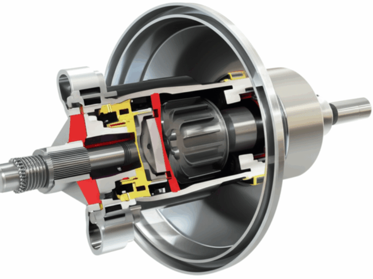
The stator does not spin. The rotor does. The stator holds the magnetic field source or the armature winding depending on the machine type. The rotor carries conductors or permanent magnets or a field winding that interacts with the stator’s field. They need each other. That’s the short version.
If you want to see how rotor stacks differ in form and steel choice compared to stator stacks, this page on rotor core lamination gives a good snapshot of the rotating side’s lamination geometry and material options: https://sinolami.com/rotor-laminations/
Where you’ll find stators: Applications that touch daily life
- Electric motors in industrial machinery, conveyors, pumps, and compressors.
- Household appliances like washing machines, refrigerators, and vacuum cleaners.
- Electric vehicles and e-bikes where traction motors pack serious power density.
- Drones and robotics that use compact, high-efficiency BLDC or PMSM units.
- Power plant generators in hydroelectric, wind, gas, and steam applications.
- Automotive alternators that keep a car battery charged.
- Marine alternators and generators for ships and offshore platforms.
- HVAC systems that run fans and blowers around the clock.
- Specialized aerospace actuators and precision motion systems.
A wind turbine generator has a stator that handles large currents at variable frequency as the rotor spins with the wind. A hydroelectric generator’s stator might run for decades with careful maintenance. A small drone motor stator balances concentrated windings and thin laminations to keep weight low and efficiency high.
Types of stators and winding styles
By machine: AC, DC, and generators
- AC motor stator: Creates a rotating magnetic field when fed by single-phase or three-phase AC. Common in induction motors and synchronous motors.
- DC motor stator: Provides a stationary magnetic field via a field winding or permanent magnets. The armature winding sits on the rotor.
- Generator stator: Holds the armature winding in AC machines. The stator produces the power that feeds the load.
By winding layout: Distributed vs concentrated
- Distributed windings spread coils across multiple slots per pole per phase. They produce a smoother EMF waveform and lower harmonic content which helps efficiency and reduces torque ripple.
- Concentrated windings pack coils into fewer slots per pole per phase. They simplify manufacturing and can improve power density in compact machines which is why BLDC and some PM machines use them. They can increase harmonic content and cogging unless you optimize the geometry.
By phases: Single-phase and three-phase
- Single-phase stator: Common in small appliances and residential HVAC. Needs auxiliary windings or a capacitor to start. It runs simpler which suits low-power setups.
- Three-phase stator: The workhorse of industry. It creates a naturally rotating magnetic field and delivers smooth torque. It also scales well for large power.
By motor family: Induction, synchronous, BLDC, PMSM, SRM, universal
- Induction motor stator: Usually a three-phase distributed winding fed by AC. The rotor can be a squirrel cage or a wound rotor with slip rings.
- Synchronous motor stator: Similar stator windings to induction machines yet designed to lock rotor speed to the rotating field. That includes PMSM and wound-field synchronous machines.
- BLDC stator: Often concentrated windings with electronic commutation. Despite the name these are AC machines driven by inverters.
- PMSM stator: Like BLDC in hardware but often uses sinusoidal current and control for smoother torque. Great for EVs and robotics.
- Switched reluctance motor (SRM) stator: Salient poles with concentrated windings. No rotor windings or magnets. Control is different since torque comes from changing reluctance as rotor poles align with energized stator poles.
- Universal motor stator: Series-wound design that runs on AC or DC which you see in handheld tools and small appliances. The stator uses a field winding in series with the armature.
Design choices that drive efficiency, torque, and power density
Magnetic circuit and core losses
I always start with the magnetic circuit. The stator core channels flux where it needs to go. Silicon steel grade, lamination thickness, and stacking factor all affect losses and saturation. Core losses include eddy currents and hysteresis. They can account for 20–50% of total electrical losses in some motors if you do a poor job on materials or flux density. Thin laminations and proper alloy selection cut those losses. Careful slot tooth geometry helps as well.
If you want to browse common motor-grade stacks and their lamination families you can scan motor core laminations here which cover both stator and rotor stacks used across machines: https://sinolami.com/motor-core-laminations/
Winding choices, EMF, and slot geometry
Winding layout tunes EMF generation. Faraday’s law guides the voltage per turn based on flux per pole and speed. Change the number of poles and you change base speed for a given frequency. Change the slot count and you shift harmonics and torque ripple. Choose between distributed and concentrated windings based on waveform quality, manufacturing ease, and slot fill.
Current density in windings sets copper loss and temperature rise. Push current density too high and you cook insulation or hit thermal limits. Under-fill the slot and you waste space. Hairpin windings boost fill and reduce AC resistance at high frequencies if you design the shape right. That matters in high-speed motors where skin and proximity effects show up.
Thermal management and insulation classes
The stator’s thermal path runs from copper to insulation to iron to housing to air or liquid. Improve any link and you drop temperature. Varnish impregnation and vacuum pressure impregnation (VPI) reduce voids and improve heat transfer while also locking coils in place. Resin encapsulation can go further for rugged duty. Higher insulation classes let you run hotter which can lift power density if the rest of the system can shed heat.
I’ve used simple ribbed housings, buried cooling jackets, and direct spray cooling onto the end-turns. Each method trades complexity for performance. Direct liquid cooling through the stator can cut winding temperatures by 10–30°C compared to air cooling in the same footprint. That often means a lighter machine for the same output.
High-speed vs low-speed stators
High-speed machines need low losses at higher electrical frequency since core loss scales with frequency and flux density. You use thinner laminations, lower flux swings, and careful winding to cut AC resistance. End-turn length matters a lot since long end-turns add copper loss that does not contribute to torque.
Low-speed machines chase high torque with more poles and larger diameter. They can tolerate thicker laminations and more copper mass since frequency stays low. Wind turbine direct-drive generators show the extreme here. They pack huge stators with many poles to generate power at slow rotor speeds.
Manufacturing and cost: From laminations to life on the line
Stator manufacturing looks simple at a glance. It is not. You start with a coil of electrical steel then stamp or laser-cut laminations. You stack them with interlocks, bonding, or welding. You insulate the slots. You insert coils or shape hairpins and weld their ends. You impregnate with varnish or resin. You cure it then machine critical fits and assemble into the frame.
Every step can bite quality if you rush it. Burrs from stamping increase local losses and heat. Poor slot insulation sets you up for turn-to-turn faults. Low cure on varnish lets coils move and rub. Even loose wedges can lead to vibration, noise, and shorts.
Costs tell a blunt story. Copper and steel dominate the bill. Stator manufacturing can run 30–60% of the motor’s total cost depending on size and complexity. Automation changes the picture. Automated winding and insertion can drop labor hours by up to 70% in high-volume production. You pay for tooling and equipment up front. You get consistency and speed back.
When you want to go deeper on stacked steel options for stators you can review stator-specific lamination information here: https://sinolami.com/stator-laminations/
For material choices and steel grades that drive performance the overview here helps connect the dots between chemistry and loss: https://sinolami.com/silicon-steel-laminations/
Reliability, failure modes, and maintenance that actually works
In my experience winding insulation causes most stator failures. Older fleets show statistics that put insulation issues at something like up to 80% of breakdowns. Heat, vibration, contamination, and voltage spikes eat insulation slowly then it fails quickly.
Common failure modes
- Turn-to-turn faults that short adjacent turns. These start as partial discharge or abrasion then cascade.
- Ground faults where a winding contacts the core. That can come from nicked slot liners, debris, or thermal stress.
- Thermal aging that cracks enamel and varnish. Repeated starts or high current density hasten this.
- Core hot spots from poor lamination bonding or damage. That raises local hysteresis and eddy losses.
Prevention and maintenance that pay off
- Keep the stator clean and dry. Moisture and dust accelerate tracking and partial discharge.
- Use VPI and high-grade insulation systems when duty is tough. It improves life by a wide margin.
- Watch temperature with embedded sensors if possible. Long life correlates with lower thermal cycling.
- Test smart. Surge tests find weak turn insulation. Hi-pot and megger tests track ground wall health. Partial discharge tests reveal incipient problems in high-voltage machines.
- Balance the rotor and align bearings. Vibration hurts insulation even though the stator does not move.
- Control voltage spikes from inverters with proper filtering and cable choices. Fast edges can nick insulation over time.
Large utility generators often run 40–50 years with disciplined maintenance. Industrial motors can last 15–30 years. Abuse shortens that life fast. Good thermal design and clean power extend it.
Two short stories that shaped how I think about stators
- The student lab rewind. I once helped a student team rewind a small induction motor after a turn-to-turn fault toasted a phase. We learned three big lessons. Do not skimp on slot liners. Do not yank coils with pliers because you will nick the enamel. Do bake the varnish long enough or the end-turns will hum and rub. That motor ran smoother and cooler after we did it right.
- The EV hairpin trade. I sat in a design review where we weighed round-wire distributed windings against hairpin windings for a traction motor stator. Hairpins promised a higher copper fill and shorter end-turns which helps power density. They also demanded precise forming and laser welding plus robust insulation at sharp bends. We chose hairpins because we needed the kW per kilogram. We budgeted time for a tight manufacturing process. That stator hit its thermal and torque targets which made the extra care worth it.
FAQs: Straight answers to common stator questions
What is a stator in simple words?
It is the stationary part of a motor or generator that holds the core and windings. It creates or receives magnetic fields that interact with the rotor to make power or torque.
How does a stator work in an AC motor?
A three-phase AC stator creates a rotating magnetic field. That field induces current in the rotor of an induction motor or pulls a permanent magnet rotor along in a synchronous motor. The interaction produces torque.
How does a stator work in a generator or alternator?
A magnetic field on the rotor sweeps past the stator windings. Changing flux induces voltage per Faraday’s law. Current flows to the load. The stator acts as the armature in many AC generators.
What is in a stator winding?
Insulated copper coils placed in stator slots. The insulation can include enamel on the wire, slot liners, wedges, varnish, tapes, and resin.
Why use laminations in the stator core?
Thin silicon steel laminations reduce eddy currents and hysteresis losses. That boosts efficiency and cuts heat.
What causes a stator to fail?
Heat, vibration, contamination, and electrical stress. Turn-to-turn faults and ground faults top the list.
What does “poles” mean on a stator?
Poles describe how many north-south magnetic pairs the stator field creates. More poles mean lower synchronous speed at a given frequency and often higher torque at low speed.
What is the difference between stator and rotor?
The stator does not move and holds windings that create or receive the field. The rotor moves and carries conductors or magnets that interact with that field.
What is a squirrel cage induction motor stator?
It is a standard three-phase stator with distributed windings. The rotor uses conductive bars and end rings to form a “cage” that the stator field induces current into.
What is a wound rotor induction motor stator?
It looks similar to a squirrel cage stator. The difference sits on the rotor which has windings connected through slip rings for control.
What is a permanent magnet motor stator?
A stator with windings that produces a rotating field for a rotor that carries permanent magnets. That includes PMSM and BLDC machines.
What is a switched reluctance motor stator?
A stator with salient poles and concentrated windings. Torque arises as rotor poles align with energized stator poles due to changing reluctance.
How do single-phase and three-phase stators differ?
Single-phase stators use auxiliaries to start and run with more ripple. Three-phase stators create a natural rotating field that delivers smoother torque.
What is varnish impregnation or VPI?
Processes that soak windings in insulating varnish then cure it. VPI uses vacuum and pressure to remove air and fill voids which boosts dielectric strength and heat transfer.
Can you repair a stator?
Yes. Rewinding shops strip old coils, inspect cores, insert new coils, and re-impregnate. Success depends on core health and economics.
How do you reduce noise from a stator?
Optimize slot and tooth geometry to cut electromagnetic forces at problem frequencies. Tighten wedges and end-turn support. Improve VPI. Balance the rotor and adjust PWM strategies.
What is the armature in a DC motor?
In a traditional DC motor the armature winding sits on the rotor. The stator provides the field winding or magnets.
Is higher power density always better?
It depends. Higher power density raises thermal stress and often demands advanced cooling and insulation. You gain compactness and weight savings. You must design carefully.
Conclusion: The quiet cornerstone of electrified life
When I first asked what those stacks of steel were I thought a stator was just metal and wire. I was wrong. The stator is a carefully engineered magnetic circuit that guides flux, carries current, manages heat, and quietly does the heavy lifting in motors and generators. It works with the rotor like a dance partner. Together they convert energy with grace when you respect the details.
If you remember nothing else remember this. A good stator design starts with a sound magnetic path, a sane slot and tooth layout, and a winding that fits with the right insulation. Manage heat early. Pick materials that limit core losses. Keep your manufacturing clean. Do that and your stator will run cooler, last longer, and turn more of your input into useful torque or power.
If you want to dig deeper into the building blocks that make stators efficient these resources offer clear views into the steel and stacks that sit at the heart of it:
That’s the stator. Fixed in place yet central to motion and power in the modern world.