What Is a Simple Electric Motor? Definition, How It Works, and Why Laminations Matter
Every design engineer faces the same balancing act. You want higher motor efficiency, tighter torque control, and a safer thermal profile. You also have production targets and cost constraints. If you have ever asked how lamination thickness, material grade, or manufacturing method will affect efficiency and lifetime you are not alone. The core lamination stack sits at the center of that conversation because it sets the tone for magnetic performance, thermal losses, and manufacturability.
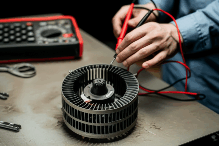
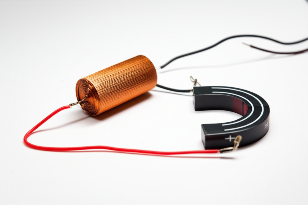
Let’s start with the basics. A simple electric motor is a device that converts electrical energy into mechanical energy. It does this through electromagnetism. In its simplest form you can build one with a battery, a coil of copper wire, and a pair of permanent magnets. That little science fair motor makes an invisible interaction visible. It turns current into torque and rotation. The same physics drives every DC motor, AC motor, brushless motor, and generator on your production floor. The difference is in the details: materials, geometry, and especially the rotor and stator core laminations that quietly control losses and performance.
Before we dive into materials and processes, here is your roadmap.
In This Article
- Why Lamination Choices Are Critical for Performance and Cost
- A Simple Motor Refresher: The Physics You Can See
- Engineering Fundamentals: Core Losses and Magnetic Behavior
- Material Options for Motor Core Laminations
- Manufacturing and Assembly Processes That Matter
- Matching the Right Lamination Strategy to Your Application
- Quality, Testing, and Reliability Considerations
- Procurement and Design Checklist
- Hands-On: Build a Simple DC Motor to See It Work
- Your Engineering Takeaway
Why Lamination Choices Are Critical for Performance and Cost
Problem first. You need to increase motor efficiency without blowing up the bill of materials or lead time. You also need predictable torque generation across your speed range and safe operating temperatures. You might be weighing silicon steel grades, considering cobalt alloys for high frequency, or choosing between stamping and laser cutting. Maybe you are troubleshooting excess core loss, noise, or overheating in a prototype. All of these issues roll back to the electrical steel laminations inside the stator and rotor.
Here’s what is really at stake in that “simple” decision.
- Efficiency and heat: Eddy current loss scales with thickness and frequency. You can reduce it with thinner laminations and proper insulation. That cuts heat and improves efficiency.
- Torque density: Magnetic permeability and saturation flux density set how much magnetic force you can push through the motor core. Better material and smarter stack design deliver higher torque per kilogram.
- Noise and vibration: Uniform stacks with low burrs and consistent insulation reduce magnetic and mechanical noise.
- Cost and manufacturability: Tooling method, die life, and coating choice show up in unit price and yield. Stamping shines at volume. Laser cutting excels at low volume and complex rotor or stator shapes.
- Reliability and lifespan: Lower core loss reduces thermal stress. That protects bearings, insulation, and carbon brush systems in brushed DC motors and extends service life.
If you are designing a BLDC motor, a brushed DC motor, or a small AC induction motor, you cannot ignore the laminations. The quality of the motor core laminations you select will either free up performance or tax it with avoidable losses.
A Simple Motor Refresher: The Physics You Can See
A quick rewind helps. You know the story yet it is worth telling in one breath. A simple DC motor uses a battery to drive current through an armature coil. The coil sits in a magnetic field set by a permanent magnet or an electromagnet. Current in the coil creates its own magnetic field. Those fields interact. The Lorentz force acts on the conductors and generates torque. The commutator and brushes flip the current every half turn. The shaft continues to spin and convert electrical energy into mechanical energy. That is it.
- Electric motor basics: convert electrical to mechanical energy through electromagnetism.
- Components: rotor and stator, armature, commutator, carbon brush, shaft, bearings, and a simple circuit.
- Physics landmarks: Faraday’s law of induction and the Lorentz force. Fleming’s Left-Hand Rule predicts the force direction. The Right-Hand Thumb Rule helps with current and field orientation.
- Back EMF: As the coil rotates, it induces a voltage that opposes the supply. Back EMF grows with speed and naturally limits current.
You can show this to a student with a battery powered motor made from magnet wire, paper clips, and a D-cell. The simple DC motor demonstrates torque generation, rotational motion, and magnetic field interaction better than a whiteboard ever will. Michael Faraday’s early demonstrations and William Sturgeon’s electromagnet gave us the blueprint. That same blueprint drives today’s permanent magnet motors, brushless motors, and even simple linear motors.
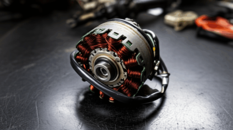
So why bring this up in a discussion about laminations? Because the laminated core guides the magnetic flux. It reduces wasted energy from circulating currents. It is the silent partner that turns a science project into a reliable product.
Engineering Fundamentals: Core Losses and Magnetic Behavior
You cannot optimize a motor until you understand where the energy goes. Two main mechanisms drive core loss in a laminated stator or rotor: eddy current loss and hysteresis loss. A third bucket contains mechanical loss from bearings and windage, and copper loss from current flow in the windings. We focus here on core losses since laminations target them directly.
- Eddy currents: Think of eddy currents like tiny whirlpools in a river. A changing magnetic field induces circulating currents inside a solid metal core. Those currents heat the core and waste energy. Laminations break the big whirlpools into small ripples. Each lamination has an insulation layer that forces the currents to take a longer, higher resistance path. Thinner laminations cut the loop size and lower the loss at higher frequencies.
- Hysteresis: Picture walking through a field of tall grass. Each step bends the grass. It never springs back perfectly straight. Magnetic domains behave the same way. Cycling the magnetic field realigns domains and wastes energy as heat. Hysteresis loss depends on the B-H curve of the material, specifically coercivity which is the resistance to demagnetization, and the number of cycles per second.
- Frequency and flux density: Loss scales with frequency and with the square of peak flux density for eddy currents. It scales roughly linearly with frequency for hysteresis. High-speed motors and high-frequency drives push these losses up.
A few more fundamentals help frame design choices.
- Magnetic permeability: How easily magnetic field lines travel through a material. Like how a sponge soaks up water. Higher permeability yields stronger flux for the same magnetomotive force which raises torque.
- Saturation flux density: The cap on how much magnetic field a material can carry before it stops responding linearly. You will meet this limit in high-torque or high-power-density designs.
- Reluctance and inductance: Reluctance is the magnetic analog of resistance. Low reluctance paths guide flux with less MMF drop. Inductance depends on geometry and material and affects dynamic behavior and current ripple.
Note the units you juggle. Volts drive current measured in amperes through coils that follow Ohm’s law. Magnetic flux lines and magnetic flux density weave through the stator and rotor. Power turns into work measured in watts and joules. You may not say these out loud on the factory floor. They live inside your torque-speed curves and efficiency maps.
Several standards govern testing and material behavior. IEC 60404 outlines how to measure magnetic properties of electrical steels. ASTM A677 covers fully processed nonoriented electrical steel sheet and strip. ASTM A876 covers flat-rolled grain-oriented silicon steel. IEC 60034 defines performance for rotating electrical machines and gives you a common language for efficiency classes. If your supplier quotes core loss in watts per kilogram at a specific frequency and flux density they likely follow these frameworks.
Material Options for Motor Core Laminations
You have two decisions intertwined. Which material to select and how thick to make each lamination. The right answer depends on frequency, flux density, size, and cost targets.
Silicon steels (electrical steel)
Nonoriented silicon steel is the workhorse for general-purpose motors and generators. It balances cost, magnetic performance, and availability.
- Pros: Good magnetic permeability, decent saturation flux density, and mature supply chains. Available in many thicknesses and insulation classes.
- Cons: Core loss rises as frequency climbs. Performance trails cobalt alloys in extreme applications.
Grain-oriented silicon steel shines in transformers since it delivers very low loss in one direction. Motors see flux rotating in the stator. That makes nonoriented grades the default for rotating machines.
You can explore more background on available laminations and grades here: electrical steel laminations.
Cobalt alloys
Cobalt-iron alloys deliver high saturation flux density and low losses at elevated frequency. Aerospace actuators and high power density machines use them when performance trumps cost.
- Pros: Superior power density. Better high-frequency behavior.
- Cons: High cost and more complex processing. Tool wear can increase in stamping.
Nickel-iron alloys
Nickel-iron can offer very high permeability and low coercivity in some compositions. Certain sensors and specialty machines use them. They come with cost and availability tradeoffs.
Soft magnetic composites (SMC)
Powdered iron with an insulating binder allows 3D magnetic flux paths and near-isotropic behavior.
- Pros: Useful for complex 3D geometries. Lower eddy currents at high frequency due to distributed insulation around each particle.
- Cons: Lower permeability and saturation versus steel. Mechanical properties differ from stacked sheet laminations.
Lamination thickness selection
Thinner laminations reduce eddy current loss. Many small motors use 0.35 mm or 0.50 mm thickness. High-speed machines may push to 0.20 mm or thinner. You balance loss reduction against cost, handling difficulty, and stacking factor.
- Stacking factor: The ratio of net steel thickness to total stack height. Insulation and surface roughness reduce it. Lower stacking factor increases the magnetic path length and changes performance. You can compensate in design or by adjusting stack height.
If you design a brushed DC motor for toys or educational kits you can live with moderate thickness because the operating frequency is lower and current consumption is modest. If you design a BLDC rotor for a drone with high RPM you will feel every extra watt of core loss. Thinner laminations pay back quickly with higher motor efficiency percentage and reduced operational temperature.
Manufacturing and Assembly Processes That Matter
The best material can underperform if the manufacturing method adds stress, burrs, or electrical shorts between laminations. Here is a quick guide to common options.
Stamping
Progressive die stamping is the standard for medium to high volume production.
- Pros: Low cycle time after tooling, tight repeatability, and good cost per part for volume. Interlocking features can be integrated.
- Cons: Upfront tooling cost and lead time. Burr formation must be controlled. Tool wear affects edge quality and dimensional accuracy.
Good practices: control burr height, use appropriate die clearances, and specify deburring if needed. Limit inter-lam electrical contact at the edges to preserve insulation. Plan for stress relief annealing when necessary to restore magnetic properties after punching.
Laser cutting
Fiber or CO2 laser cutting is a strong choice for prototyping and low volume runs.
- Pros: No dedicated tooling. Fast design changes. Works for complex geometries.
- Cons: Heat affected zone can degrade magnetic properties near cut edges. Slower than stamping for volume. Taper and micro-cracks are risks if parameters are not optimized.
Use laser for early iterations. Transfer to stamping once the geometry stabilizes if annual volumes justify the tooling. For a BLDC prototype stator or rotor stack this path saves time and cash since you can iterate slot count or skew without waiting for a die.
Wire EDM
Wire EDM produces excellent edge quality with minimal burrs and a narrow heat affected zone.
- Pros: Highest precision. Great for small slot features and tight tolerances.
- Cons: Very slow and expensive for production. Best for test stacks or critical fixtures.
Insulation coatings and bonding
Every lamination needs insulation between sheets. Organic or inorganic coatings deliver that barrier and affect stacking factor, punchability, and thermal endurance.
- Coating class: Choose a coating suitable for your operating temperature and assembly process. Some coatings tolerate welding or bonding better than others.
- Bonding: Bonded stacks use adhesive coatings or post-stacking resins. They run quiet and resist vibration. The trade is higher process cost and careful cure cycles.
- Interlocking: Mechanical dimples or tabs snap laminations together. Think LEGO bricks for steel. This creates rigid stacks without welding and preserves magnetic properties when done correctly.
- Riveting and cleating: Useful for large stacks or when you need serviceability. Rivets add local saturation points and require care in placement.
Post-processing: annealing and stress relief
Punching and cutting introduce residual stress. That stress raises loss and lowers permeability. A proper anneal restores magnetic performance. Control temperature and atmosphere to avoid oxidation and to preserve coating integrity. Not every design needs anneal. High-performance machines often benefit from it.
Stack assembly and skew
Axial or step skew in the stator or rotor reduces cogging torque and acoustic noise. You can achieve skew by stacking skewed laminations, by step skew blocks, or by shaping rotor magnets in PM machines. The right skew balances torque ripple reduction with manufacturing complexity.
If your motor requires a dedicated stator design, consider this resource for more context on the role and geometry of the stator core lamination. The complementary rotor core lamination decisions affect torque ripple and back EMF shape in equal measure.
Matching the Right Lamination Strategy to Your Application
Let’s translate the options into clear guidance by application type. You can use this as a sanity check during early design or as a procurement playbook.
Brushed DC motors for toys and tools
- Typical needs: low cost, modest power, simple commutator and carbon brush system, and basic motor maintenance. Applications include small fans, pumps, drills, and educational toys.
- Material: nonoriented silicon steel with moderate thickness like 0.35–0.50 mm. Permanent magnet stator or simple wound field.
- Manufacturing: stamping for volume. Interlock stacks to keep assembly fast.
- Trade-offs: accept higher core loss at the top end of speed to keep unit cost down. Focus on rotor balance and bearing types since noise reduction matters in consumer products.
You will see this architecture in small toy motors and battery powered devices. It aligns with motor efficiency basics and simple motor advantages such as low cost and ruggedness. The disadvantages include brush wear and electrical noise.
BLDC motors for drones, robotics kits, and small appliances
- Typical needs: high efficiency, compact size, precise speed control, and low noise. Robotics kits benefit from high torque density and easy integration with motor controllers.
- Material: finer-gauge nonoriented electrical steel. Consider 0.20–0.35 mm depending on frequency and budget.
- Manufacturing: laser for prototyping then stamping for production. Consider bonded stator stacks to cut noise.
- Special: optimize slot and tooth geometry to manage magnetic flux and reduce cogging. Use skew as needed. Coordinate with magnet grade and back EMF target waveform.
For reference, review the specific geometry considerations for a BLDC stator core lamination since slot count, tooth shape, and stack height drive both torque and core loss.
High-speed spindles and aerospace actuators
- Typical needs: high frequency operation, strict thermal limits, and tight tolerances.
- Material: cobalt-iron alloys or very thin-gauge silicon steel.
- Manufacturing: stamping with premium dies or wire EDM for critical features. Post-process anneal to recover magnetic performance.
- Trade-offs: higher material and process cost pays back in power density and efficiency. You will also manage motor current and voltage more tightly since loss grows with frequency.
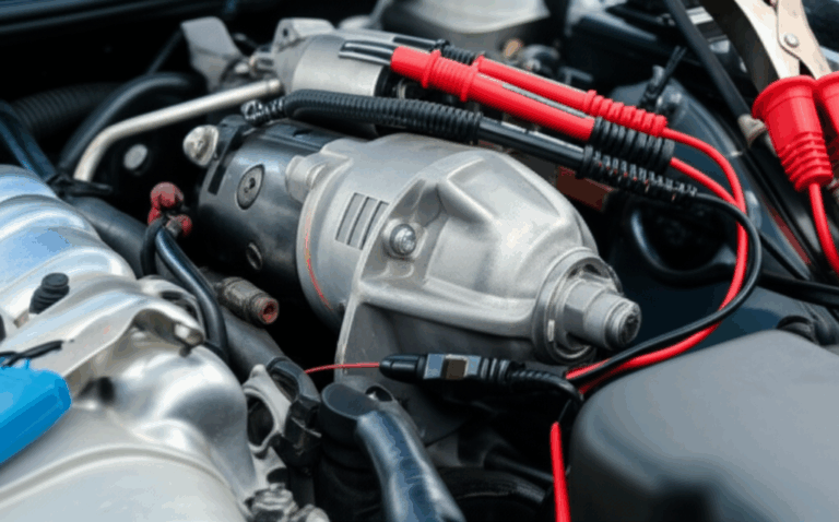
Industrial AC motors and pumps
- Typical needs: reliability, long lifespan, robust mechanical force delivery, and compliance with efficiency regulations.
- Material: nonoriented silicon steel with thickness matched to line frequency and expected harmonics from VFDs.
- Manufacturing: high-volume stamping and automated assembly. Interlocking or welding based on frame size and load. Use electrical steel laminations with coatings that tolerate the assembly process and operating temperature.
- Standards: IEC 60034 efficiency classes apply. Expect audits on performance metrics.
Transformers and allied machines
A quick note. Transformers use grain-oriented steel in E-I or U-I shapes to minimize loss along one direction. While not motors, the same principles of eddy currents, hysteresis, and lamination thickness apply. If you source EI core or UI lamination core for transformers you already speak this language.
Quality, Testing, and Reliability Considerations
You cannot manage what you do not measure. Core loss, stacking factor, burr height, and insulation integrity deserve your attention. Here is how to stay in control.
- Core loss testing: Suppliers may test individual sheets via Epstein frame or single sheet testers per IEC 60404. Finished stacks can be tested in a ring configuration or in the assembled motor with back-to-back comparison. Ask for loss in W/kg at your operating frequency and flux density. Verify test method and conditions.
- Dimensional control: Tighter tolerance on ID, OD, slot width, and tooth tip height make winding and assembly predictable. It also controls air gap and thus torque generation. Define a clear tolerance stack for shaft fit and bearing seats on rotor laminations.
- Insulation integrity: Specify coating class and dielectric requirements. Check for shorts between laminations with high potential tests on stacks sampled from each lot.
- Burr and edge quality: Set a maximum burr height based on your stacking and assembly process. Burrs can pierce insulation and raise eddy current loss. They can also increase noise.
- Mechanical checks: Evaluate balance on the rotor, skew consistency, and roundness. Bearing types and fits influence noise and lifespan.
- Thermal behavior: Measure temperature rise under load. Back EMF increases with speed which reduces current draw and heat in a healthy design. If temperature keeps climbing unchecked at speed you may have core loss issues, windage, or drive control problems.
Reliability grows from boring consistency. The more consistent your laminations and assembly the easier your life becomes. Keep an eye on future developments like bonding adhesives with improved thermal endurance and recycling-friendly coatings since they influence sustainability goals and the motor’s carbon footprint.
Procurement and Design Checklist
Empower your team with a clear checklist. It aligns engineering intent with supplier capability.
- Application description: motor type, speed range, expected load profile, and duty cycle. Define whether it is a DC motor, AC motor, brushless motor, or stepper.
- Electrical targets: voltage, current, motor efficiency percentage, torque at key points, and allowed temperature rise.
- Material callout: grade of silicon steel or alloy, lamination thickness, and coating specification. Include standards like ASTM A677 or A876 where appropriate.
- Geometry package: 2D DXF or 3D models of rotor and stator laminations with clear tolerances. Note slot count, skew strategy, and any interlocking features.
- Stack details: stack height, stacking factor target, assembly method, and whether bonding, welding, riveting, or interlocking applies.
- Quality controls: burr limit, insulation testing, core loss testing method, and sampling plan. Include motor testing methods for the assembled unit when relevant.
- Manufacturing process: stamping, laser cutting, or EDM. Include expected volume and any phase plan from prototype to production.
- Logistics: packaging, labeling, and traceability requirements. Add basic safety and legal regulations for your region.
- Sustainability: end-of-life considerations and recycling plans. Request environmental impact data if available.
If you want a one-page primer for colleagues, explain the motor’s magnetic flux path with a basic motor diagram that shows north pole and south pole interaction around the stator and rotor slots. Simple visuals speed up reviews and keep discussions grounded.
Hands-On: Build a Simple DC Motor to See It Work
Even seasoned engineers benefit from a quick bench demo. Build a simple electromotor. It reminds your team what the laminations are doing without getting lost in equations.
- Materials: AA battery, magnet wire, a pair of paper clips as brushes, a strong permanent magnet, and rubber bands for a makeshift support structure.
- Steps: Wind a coil and strip the enamel on half of each commutator end. Mount the coil on a shaft between the paper clips. Place the permanent magnet under the coil. Connect the circuit and watch rotational motion kick in as current flows.
- Observations: The coil turns because the Lorentz force acts on a current carrying conductor in a magnetic field. The half-stripped ends on the commutator reverse current at the right moment. That is simple commutation. Add more turns to increase torque. Change polarity to reverse rotation. Explain how a commutator function motor keeps spinning and how a simple motor without commutator stalls after half a turn.
Now tie it back. Your production stator core lamination or rotor stack does the same job at scale. It guides the magnetic field and limits energy waste through lamination and insulation. Students love this demonstration and so do stakeholders who need to understand why lamination material choice matters. If you prefer a quick reference, search for “DIY simple motor project” or “motor demonstration” for classroom-ready instructions. Use it to spark discussions about electromagnetism principle, Faraday’s law electric motor, and motor magnetic poles.
The Broader Context: From Classroom to Factory Floor
History matters because it helps you explain choices to non-technical teams. Hans Christian Ørsted saw a compass needle wiggle near a current-carrying wire in 1820. Michael Faraday demonstrated electromagnetic rotation in 1821. William Sturgeon built strong electromagnets in 1825. William Ritchie advanced commutation in 1832. Thomas Davenport patented an early DC motor in 1837. Nikola Tesla drove AC motor development and polyphase systems later on. Those milestones seeded everything from fans in your home to pumps, drills, and robotics kits on your bench.
Today, millions of science fair projects use simple motors to explore motor physics and magnetic field interaction. That educational ecosystem feeds the pipeline of engineers who will spec lamination thickness, select coatings, and debate motor noise reduction strategies in product design reviews. The gap between a basic electric motor design and a high-efficiency industrial drive is not a chasm. It is a series of informed decisions about the motor’s core.
Frequently Crossed Wires: Common Pitfalls and How to Avoid Them
- Overlooking VFD harmonics: Variable frequency drives introduce higher frequency components that can raise eddy current loss in the stator. Combat this with thinner laminations or improved coatings for the intended spectrum.
- Ignoring stacking factor: You designed to a magnetic path that expects 100% steel. Real stacks never reach it. Account for insulation thickness and roughness in your calculations.
- Underestimating burr impact: Small burrs create unintended electrical bridges between laminations. Loss goes up and heat follows. Set a burr spec and enforce it.
- Skipping anneal when needed: Punching stress hurts. If you see higher loss than expected test a stress relief anneal to recover performance.
- Mismatched coating and process: Some coatings do not tolerate welding or high-temperature bonding. Check compatibility early.
- Overcomplicating for low-demand applications: A simple DC motor for toys does not need ultra-thin laminations or cobalt alloys. Keep it simple and manage cost.
- Neglecting noise: A quiet motor sells itself. Consider skew, bonding, and precision bearings. Noise can stem from magnetic forces and mechanical misalignment.
Metrics That Matter: Performance and Efficiency Basics
Engineers and procurement managers speak numbers. Here are the ones that tend to drive decisions.
- Core loss: W/kg at specified flux density and frequency. Lower is better if all else is equal.
- Efficiency: Percentage of electrical energy turned into mechanical work. Watch it at your rated point and across the operating range. Basic DIY motors can sit under 10–20% efficiency due to friction and poor magnetic circuits. Production machines target far higher numbers.
- Torque and speed: Torque generation depends on flux and current. Speed control relies on back EMF and drive strategy.
- Current consumption and voltage requirements: Lower loss reduces heat and cuts current draw for a given load. That grows battery life and reduces power supply size.
- Reliability and lifespan: Lower operating temperature extends insulation life and bearing performance. Good lamination choices pay dividends here.
If your design involves a permanent magnet motor or a BLDC machine, remember that the stator core carries most of the time-varying flux. That is why stator lamination quality is so critical. Rotor laminations matter for induction machines and for saliency control in synchronous designs.
Tying It All Together With Real Options
Let’s bring the guide into focus with a simple, honest mapping.
- If you need a general-purpose motor for a pump or fan you likely need nonoriented silicon steel around 0.35–0.50 mm. Stamping and interlocking keep costs down. The goal is dependable torque and low maintenance.
- If you need high power density and high RPM you likely need thinner laminations and better coatings. Bonded stacks reduce noise. Prototype with laser then invest in stamping. Check skew to cut torque ripple.
- If you need extreme performance at high frequency you may need cobalt alloys and stress relieving anneal. You will pay more yet you will gain efficiency and lower operational temperature.
For a deeper dive on complete stack solutions and how material and process come together, review the overview for motor core laminations. That context helps when you discuss stack height, notch patterns, and QA with your supplier.
Your Engineering Takeaway
- Motor laminations exist to reduce eddy currents and hysteresis loss. They turn a simple DC motor principle into efficient, scalable machines.
- Material choice sets the ceiling. Nonoriented silicon steel handles most applications. Cobalt alloys serve high-frequency and high-density niches.
- Lamination thickness drives eddy current loss. Thinner laminations win at high speed and high frequency.
- Manufacturing method matters. Stamping rules for volume. Laser and EDM serve prototypes and complex shapes. Manage burrs and stress.
- Assembly and coatings impact noise, stacking factor, and reliability. Pick interlocking, bonding, or riveting based on load and volume.
- Test and verify. Ask for core loss data per IEC 60404 methods and align expectations with ASTM specs. Measure efficiency under real load.
- Match the stack to the job. Fans, pumps, drills, and toys can use simpler stacks. Robotics and BLDC designs benefit from finer gauge and better coatings.
- Educate your team. Use a simple motor demonstration to explain torque generation, commutation, and the magnetic circuit.
Ready to translate these principles into a drawing package or a sourcing brief? Bring your target efficiency, operating frequency, and stack geometry to your technical consultation. If you are reviewing stator details start with the stator core lamination geometry and insulation plan. If your focus is rotor behavior and torque ripple control explore your rotor core lamination options early. For high-level material discussions and grade availability lean on the overview of electrical steel laminations. BLDC designers can align slot geometry and stack height with the references for a BLDC stator core lamination.
If you want a final sentence to share with a non-specialist stakeholder, try this. A simple electric motor works because magnetic fields push on currents. Laminations make that push efficient, cool, and quiet at scale.