What is a Laminated Core? Understanding Its Role in Electrical Efficiency
Table of contents
- The Core Concept: Definition and Basic Structure
- What is a Laminated Core? (Simple Definition)
- How a Laminated Core is Constructed (Thin Sheets, Insulation, Stacking)
- Contrasting with Solid Iron Cores
- Why Laminated Cores Are Essential: Reducing Energy Losses
- Understanding Eddy Currents (The Primary Problem)
- How Laminations Drastically Reduce Eddy Current Losses
- Hysteresis Losses (Another Key Consideration)
- Key Materials and Properties of Laminated Cores
- Electrical Steel (Silicon Steel): The Material of Choice
- Types of Electrical Steel: GOES vs. NOES
- The Importance of Insulation (Varnish, Oxide Coatings)
- Applications: Where You Find Laminated Cores
- Power Transformers (Transmission and Distribution)
- Electric Motors (Induction, Synchronous)
- Generators (Producing Electricity)
- Inductors and Choke Coils
- Other Electrical Devices (Power Supplies, Ballasts)
- Advantages and Benefits of Using Laminated Cores
- Increased Energy Efficiency and Reduced Power Consumption
- Lower Heat Generation and Improved Device Lifespan
- Reduced Operating Costs
- Enhanced Performance and Reliability
- Lamination Manufacturing Process and Design Considerations
- From Steel Coil to Finished Lamination (Punching, Stacking)
- Lamination Thickness and Its Impact on Losses
- Core Geometry: E-I, U-I, Toroidal, and M-Type Laminations
- The Future of Core Technology
- Advancements in Core Materials (Amorphous, Nanocrystalline Cores)
- Continued Focus on Ultra-High Efficiency
- Conclusion: The Unsung Hero of Electrical Systems
- Recap of Laminated Core Importance
- Final Thoughts on Efficiency and Modern Technology
The Core Concept: Definition and Basic Structure
What is a Laminated Core? (Simple Definition)
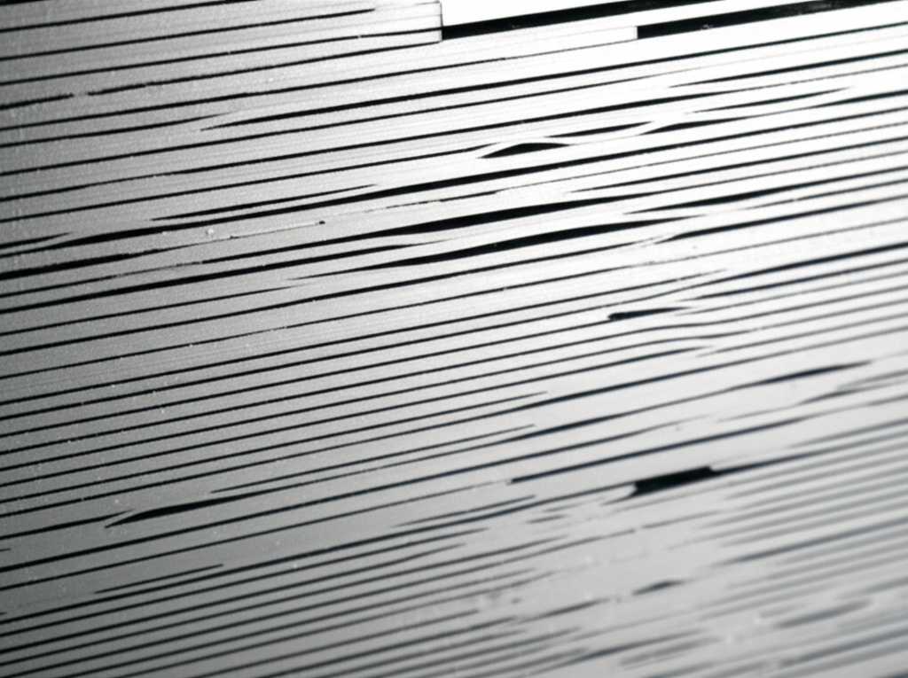
When I first opened a transformer in the lab I expected a single block of iron. Instead I found a neat stack of thin metal sheets bound together like a tightly pressed book. That stack is the “laminated core.” In simple terms a laminated core is a magnetic core made from many thin sheets of electrical steel. Each sheet has a thin insulating layer so current cannot freely circulate from one sheet to the next. We stack and clamp those sheets to form the magnetic path that guides magnetic flux in transformers, electric motors, generators, inductors, and choke coils.
Why go through the trouble of stacking sheets. Because alternating magnetic fields try to induce circulating currents in the core called eddy currents. Laminations break up those current paths. They reduce power losses and heat. That one choice changes the efficiency of almost every AC electrical machine we use.
How a Laminated Core is Constructed (Thin Sheets, Insulation, Stacking)
I learned to think of a laminated core as a sandwich. The bread slices are thin steel sheets. The butter is a very thin insulating layer like varnish, oxide, or phosphate coating. Each sheet is only 0.18 mm to 0.65 mm thick for power frequency designs at 50 or 60 Hz. High frequency applications use even thinner gauges or entirely different materials like ferrite or nanocrystalline ribbons.
We stamp or die-cut these sheets into shapes such as E and I pieces for transformers, stator and rotor slots for motors, or toroidal rings for compact inductors. After cutting, the sheets get stacked in alternating patterns that minimize air gaps. We clamp or bond the stack to maintain a high stack factor. That stack factor tells me how much of the cross section is actual metal vs insulation and voids. A higher stack factor usually means better performance because magnetic reluctance stays low.
Contrasting with Solid Iron Cores
Before I saw it in person the idea felt abstract. Then I did the experiment. We used a solid iron core with an AC winding in a demo. It heated up fast. Efficiency dropped like a stone. It hummed loudly as magnetostriction shook the mass. Switch to a laminated core and the difference felt dramatic. Eddy current losses plummeted by orders of magnitude. In real machines laminated cores reduce eddy current losses by 90 to 99% compared to a solid core of the same material. That means far less heat, higher transformer efficiency, and happier engineers.
Why Laminated Cores Are Essential: Reducing Energy Losses
Understanding Eddy Currents (The Primary Problem)
Eddy currents are the electrical equivalent of whirlpools that form when a river bends. An alternating magnetic field induces voltages in any conductive core. Those voltages drive circulating currents within the metal. The currents waste power as heat and they oppose the changing magnetic field. That hurts energy conversion efficiency.
I remember this best with a quick image. Take a big solid iron plate and wave a strong magnet near it. You feel the drag. Those are eddy currents fighting the change. In a transformer or motor you do not want that fight. It turns usable energy into heat.
Mathematically eddy current loss rises with the square of lamination thickness and with frequency squared. It also depends on the resistivity of the core material and magnetic flux density. This is why thin-gauge electrical steel with higher resistivity beats plain iron for AC applications. If you push frequency higher the eddy current problem grows fast. Designers either go thinner or switch materials.
How Laminations Drastically Reduce Eddy Current Losses
Laminations attack eddy currents on two fronts. They raise the electrical resistance in the direction of the unwanted current flow and they shorten the loop paths. Each sheet has a thin insulating coating so a current cannot hop easily from one sheet to the next. The current loop shrinks inside each sheet which reduces the magnitude of induced currents. Thin sheets crank up the resistance further and cut the loop area more. The result is a dramatic drop in eddy current loss.
In real builds I have seen how a change from 0.5 mm to 0.35 mm laminations trims core loss noticeably at 50 Hz. The improvement feels even bigger in higher frequency designs. You pay for that performance though. Thinner laminations increase manufacturing complexity and can reduce stack factor slightly because the proportional area of insulation grows. The trade-off often pays back through lower power loss and cooler operation.
Hysteresis Losses (Another Key Consideration)
Eddy currents are not the whole story. Hysteresis losses arise because the core’s magnetic domains do not line up and relax without friction. Every AC cycle forces the domains to rotate and flip. Energy gets lost in this magnetization loop. The B-H curve for the material shows this as a loop area. Larger loop area means higher hysteresis loss.
We pick soft magnetic materials with narrow B-H loops to cut hysteresis loss. Silicon steel does well because silicon increases electrical resistivity and improves magnetic domain behavior after proper annealing. You will also see amorphous metals and nanocrystalline alloys in high-efficiency designs because their domain walls move with less friction. Lower hysteresis loss keeps idle or no-load losses small in transformers and improves part-load efficiency in motors.
Key Materials and Properties of Laminated Cores
Electrical Steel (Silicon Steel): The Material of Choice
Electrical steel or silicon steel became the workhorse for laminated cores for good reasons. It offers high magnetic permeability, decent resistivity, and low core loss when processed right. After cold rolling and annealing the grains align in a way that benefits magnetic domain motion. That alignment can be directional or non-directional depending on the final application.
When I evaluate a core material I look at:
- Permeability of the core over the operating flux density range
- Resistivity of the core material which fights eddy currents
- Hysteresis loss characteristics via core loss curves or B-H data
- Saturation flux density which sets the ceiling for usable flux
- Temperature stability and how losses shift with heat
If you want a quick tour of options and formats you can browse typical electrical steel laminations used in transformers, motors, and generators. The shapes vary yet the intent stays the same. Guide flux efficiently with minimal loss.
Types of Electrical Steel: GOES vs. NOES
Two families dominate:
- Grain-Oriented Electrical Steel (GOES): The rolling process produces strong magnetic anisotropy with grains aligned to favor the rolling direction. GOES shines in transformers where the flux mainly follows a fixed direction. That alignment yields very low core loss and high permeability along the rolling direction. You will hear trade names like CRGO which stands for cold-rolled grain-oriented.
- Non-Oriented Electrical Steel (NOES): The grains have no preferred alignment which yields more uniform properties in all directions. NOES suits motors and generators where flux rotates through 360 degrees in the stator and rotor. You will see CRNO or CRNGO used in motor laminations.
I pick GOES for a power transformer core and NOES for an induction motor stator every time. The application tells you what you need.
The Importance of Insulation (Varnish, Oxide Coatings)
The thin insulating layer between laminations matters more than it looks. It raises interlaminar resistance so eddy currents cannot jump between sheets. It also protects against corrosion and can improve dielectric strength. Common coatings include varnishes, phosphate films, or controlled oxide layers formed during annealing. The coating must survive punching and stacking without flaking. If it cracks the stack factor and insulation performance suffer.
I have seen core loss measurements swing due to poor coating integrity. Good coatings and proper annealing stabilize magnetic domains and preserve low-loss behavior. Quality control teams check coating thickness, surface insulation resistance, and adhesion as part of routine inspections.
Applications: Where You Find Laminated Cores
Power Transformers (Transmission and Distribution)
Transformers live or die by their core performance. In distribution and power transformers the core sees an alternating flux at 50 or 60 Hz. Laminated GOES cores with E-I or step-lap constructions reduce both eddy current and hysteresis losses. Modern designs achieve over 99% efficiency at full load. That level only happens because the core does not waste much energy at no load.
When you open a transformer you will find E-I stacks or wound cores. You might also hear about step-lap jointing that staggers the cut edges to reduce localized flux crowding and magnetizing current. If you want a practical view of formats you can look at a typical transformer lamination core to see how those E and I pieces build the magnetic path.
Eddy currents also couple to the tank and structural parts which can cause stray losses and transformer hum. Designers use magnetic shunts and careful clamping to keep stray flux and magnetostriction noise under control.
Electric Motors (Induction, Synchronous)
Motors convert electrical energy to mechanical torque and back again when used as generators. The stator and rotor cores are laminated to minimize eddy currents under rotating fields. In induction motors the stator creates a rotating magnetic field and the rotor develops currents in its bars that chase that field. Both the stator and the rotor need laminations to keep iron losses in check.
I have seen overall motor losses drop significantly when switching to higher grade NOES with thinner gauge laminations. That change helps motors hit IE3 and IE4 efficiency classes which saves real energy over years of operation. If you want a quick reference on components, the stator core lamination defines the stationary magnetic path and slot geometry that holds the windings. The rotor core lamination forms the rotating magnetic path and slots for rotor bars or permanent magnets in various designs.
Generators (Producing Electricity)
Generators are motors run in reverse. The core sees similar rotating fields and similar loss mechanisms. Laminated stators and rotors reduce iron losses and heat which improves reliability. In high-speed machines thin laminations and careful balancing keep noise and vibration under control as well.
Inductors and Choke Coils
Inductors and choke coils in power electronics often use laminated cores for line-frequency applications or ferrites for higher frequencies. For low-frequency chokes a laminated E-I or U-I core with a small distributed gap handles significant magnetizing current without saturating. The gap sets the inductance and linearity. For high-frequency switch-mode supplies, ferrite or powdered iron usually wins because eddy current losses explode in steel at tens of kilohertz.
Other Electrical Devices (Power Supplies, Ballasts)
You will find laminated cores in older magnetic ballasts, audio transformers, line-frequency power supplies, and large electromagnets. In each case the goal stays the same. Provide a low-reluctance path for magnetic flux while minimizing eddy current and hysteresis losses.
Advantages and Benefits of Using Laminated Cores
Increased Energy Efficiency and Reduced Power Consumption
Every watt not burned as heat in the core turns into savings or extra output. Laminated cores reduce eddy currents and tighten the magnetization loop. Modern power transformers break 99% efficiency in part because their cores waste so little energy at 50 or 60 Hz. Motors benefit as well since iron losses can account for 20 to 30% of total losses if left unchecked. I have watched upgrades to better laminations shave several percentage points off motor losses. Those points stack up across industrial fleets.
Lower Heat Generation and Improved Device Lifespan
Heat kills insulation. It dries varnish. It accelerates aging in windings and bearings. When the core runs cooler, everything around it benefits. Lower iron losses reduce hot spots and keep temperatures in a safe envelope. That margin translates into longer insulation life and fewer unplanned shutdowns. In big transformers lower core loss also reduces the need for aggressive core cooling systems.
Reduced Operating Costs
Core loss occurs whenever the device is energized regardless of load. That no-load loss adds up over months and years. Utilities track it carefully because small improvements in core loss across a large fleet translate into real money. In industrial motors higher efficiency means lower electricity bills and less strain during peak demand. The material cost for better laminations can pay back quickly.
Enhanced Performance and Reliability
A well designed laminated core improves magnetizing current, reduces inrush in transformers, and keeps flux density within the linear region to avoid saturation. It also lowers acoustic noise since magnetostriction has less energy to work with. Vibration drops and the machine feels more solid. I have traced humming issues back to poor lamination stacking or loose clamps. Fix the core and the noise fades.
Lamination Manufacturing Process and Design Considerations
From Steel Coil to Finished Lamination (Punching, Stacking)
The journey starts with a coil of electrical steel. Manufacturers slit to the required width then stamp or laser-cut laminations. Punching creates burrs which can impact interlaminar insulation and stack factor if not controlled. Laser cutting reduces mechanical stress yet can alter local properties if heat is not managed. After cutting, parts may go through stress relief annealing to restore magnetic properties and align magnetic domains. Quality control checks include dimensional tolerances, coating integrity, and core loss testing on sample stacks.
During assembly the stack gets built with alternating orientations when needed. In E-I cores for example the E pieces might alternate orientation to distribute joints which reduces localized magnetic reluctance. In step-lap transformer cores the joint faces overlap in stages to smooth the flux path. Stacking pressure matters because gaps raise reluctance and push flux density up elsewhere.
Lamination Thickness and Its Impact on Losses
I always consider lamination thickness early. At 50/60 Hz typical thickness falls between 0.18 mm and 0.65 mm. Thinner laminations reduce eddy current losses which roughly scale with the square of thickness. They also increase manufacturing complexity and can lower stack factor. Thinner means more layers for the same cross section which means more interfaces and a higher proportion of insulation. There is a sweet spot for each design where core loss, cost, and manufacturing ease meet.
Frequency dependence matters too. At higher frequency you either go very thin or you switch materials. Ferrites have high electrical resistivity which kills eddy currents at tens of kilohertz. Nanocrystalline ribbons offer very low core loss at medium frequencies. Amorphous metals cut no-load loss in distribution transformers by up to 70% compared to conventional silicon steel. That shift now shows up in utility specifications where lifecycle cost beats first cost.
Core Geometry: E-I, U-I, Toroidal, and M-Type Laminations
Core geometry shapes flux paths and sets how windings fit.
- E-I laminations: Common in transformers and chokes at line frequency. Easy to manufacture and assemble. You can also buy ready sets like transformer lamination core with standard sizes and window dimensions.
- U-I laminations: Similar benefits with easier winding placement on the U leg before closing with an I bar.
- Toroidal cores: Continuous flux path with minimal air gaps and low stray fields. Great efficiency and low hum. Winding can be tricky without special tooling.
- M-type and step-lap configurations: Used to minimize joint losses and reduce magnetizing current.
- Stator and rotor laminations: Shaped with slots to hold copper windings or rotor bars and to define flux paths. For motors you can dive deeper into stator core lamination and rotor core lamination patterns because slot shape, tooth width, and stack length all affect torque, inductance, and losses.
In all cases the goal is the same. Provide a low-reluctance path for magnetic flux with minimal eddy current loops and a practical place to put the windings.
The Future of Core Technology
Advancements in Core Materials (Amorphous, Nanocrystalline Cores)
Materials science keeps pushing the boundary. Amorphous metal ribbons have no long-range crystalline order. Their domain walls can move with minimal energy loss which slashes no-load losses in distribution transformers. Utilities use them when they want top efficiency even if material cost runs higher. Nanocrystalline alloys sit somewhere between amorphous and crystalline. They deliver very low loss and high permeability across a wide frequency range.
I see amorphous cores in transformers that stay energized 24/7 with significant no-load time. They shine there. Nanocrystalline cores appear in high-performance inductors, power electronics resonators, and certain medium-frequency transformers. Soft magnetic composites and distributed gap cores also show promise because they reduce eddy currents in 3D shapes. Designers mix and match materials based on frequency, flux density, and thermal constraints.
Continued Focus on Ultra-High Efficiency
Regulations and energy prices keep pushing equipment toward higher efficiency. Motors target IE3 and IE4 classes. Transformers face tighter limits on core loss. That pressure encourages thinner gauges, better coatings, improved annealing, and smarter geometries that reduce magnetostriction and acoustic noise. I also see more attention on magnetization curves and core excitation current. Reducing magnetizing current improves power factor and shrinks inrush in transformers. That helps with upstream protection coordination and limits stress on the grid.
We should not forget recyclability and environmental impact. Electrical steel is recyclable. Coatings and processing steps continue to evolve so manufacturers can hit performance targets with less environmental cost. Those changes matter at scale because global demand for electrical steel and laminations continues to grow.
Extra Insights That Tie It All Together
I want to go a bit deeper into a few design ideas that often raise questions.
- Flux density and saturation: We size the core cross section to keep magnetic flux density within a safe range below saturation. If you run the core near saturation the B-H curve steepens and losses surge. Harmonics also distort the flux waveform which raises local peaks and can cause hot spots.
- Magnetic reluctance and flux paths: Think of reluctance as the magnetic analog of resistance. A continuous steel path has low reluctance and carries flux easily. Air gaps have high reluctance. We minimize unintended gaps at joints to avoid flux crowding and localized heating.
- Frequency dependence of losses: Eddy currents scale with frequency squared. Hysteresis loss roughly scales with frequency and the area of the B-H loop. That is why designs for 400 Hz aviation systems use much thinner laminations than 50/60 Hz grid equipment.
- Magnetic anisotropy and domain walls: Grain-oriented steels take advantage of easy magnetization directions inside the crystal structure. Annealing sets domain structures and relieves stress so domains move freely. Punching and machining introduce stress that hurts performance. Stress relief annealing recovers those losses.
- Electrical conductivity vs magnetic behavior: You want high permeability and low conductivity for AC cores. Silicon boosts resistivity without killing magnetic properties. Coatings block interlaminar conduction. Ferrites take this to an extreme with very high resistivity, which is why they dominate high frequency transformers.
- Noise, vibration, and magnetostriction: Magnetostriction causes the core to physically change dimensions as it magnetizes. That movement creates the classic transformer hum. Laminations, proper clamping, and step-lap joints reduce the vibration amplitude. Lower core loss also reduces the energy available to feed audible noise.
- EMI and leakage: Laminated cores help with containment, yet stray flux still exists. Designers use shield windings, magnetic shunts, and careful layout to reduce electromagnetic interference. Toroids help because their closed path produces less leakage.
- Thermal management: Lower core loss reduces heat generation. You still need good cooling. Transformers may use oil or forced air. Motors use fans or liquid cooling. Keeping core temperature in check maintains material properties over time and prevents insulation breakdown.
- Quality control and standards: I lean on standards for material properties, core tests, and dimensions. Core loss testing, permeability checks, and B-H curve measurements catch outliers. Stack factor gets measured because it hits effective cross section and reluctance. Coating dielectric strength and interlaminar resistance matter too.
- Practical failure modes: I have traced failures to poor stacking pressure, burrs that bridged insulation, and incorrect lamination grades. One motor rebuild had noticeable hotspots near the stator teeth. Microscopy showed coating damage from aggressive punching. Switching to better tooling and adding stress relief annealing fixed it.
Putting It Into Practice: A Simple Walkthrough
Let me share a quick design thought process for a 50 Hz transformer core.
This simple process has saved me from headaches more than once. It forces early decisions on the laminated core that ripple through efficiency, cost, and noise performance.
The Future Meets the Fundamentals
Some trends feel inevitable. Variable frequency drives push motors across wide speed ranges which change core losses with frequency. Designers respond with better NOES grades and thin gauges. Power electronics step up with higher switching frequencies which favor ferrites and nanocrystalline cores in magnetics. Utilities adopt amorphous steel in distribution transformers because lower no-load loss pays off over decades.
All that change still rests on the same physics. Alternating fields induce eddy currents. Laminations break the loops and raise resistance. Magnetic domains flip each cycle and lose energy to hysteresis. Materials and geometry set the loss and saturation behavior. Once you internalize that logic, every new core technology feels like a smarter way to limit those two loss mechanisms.
Conclusion: The Unsung Hero of Electrical Systems
Recap of Laminated Core Importance
A laminated core is a stack of thin, insulated sheets of electrical steel. We use it to guide magnetic flux with minimal losses in AC machines. Laminations cut eddy currents by breaking up current paths and raising resistance. Soft magnetic materials like silicon steel reduce hysteresis loss by allowing domain walls to move with less friction. Together they boost efficiency, reduce heat, and improve reliability in transformers, motors, generators, and inductors.
Final Thoughts on Efficiency and Modern Technology
I have lost count of how many times laminated cores made or broke a design. When the core runs cool and quiet, the rest of the machine falls into place. You hit efficiency targets, protect insulation, and avoid surprise failures. If you are exploring materials or planning a design, start with the core. It is the heart of every magnetic device. Get the laminations right and everything downstream gets easier.
If you want to see how these ideas show up in real parts, scan examples of electrical steel laminations, browse a standard transformer lamination core, or look at motor-specific stator core lamination and rotor core lamination. Those shapes bring the principles to life.
Practical tip to close this out. When in doubt, reduce lamination thickness for AC applications, verify coatings and stack factor, and keep flux density honest. Do that, and your laminated core will quietly carry the load for decades.