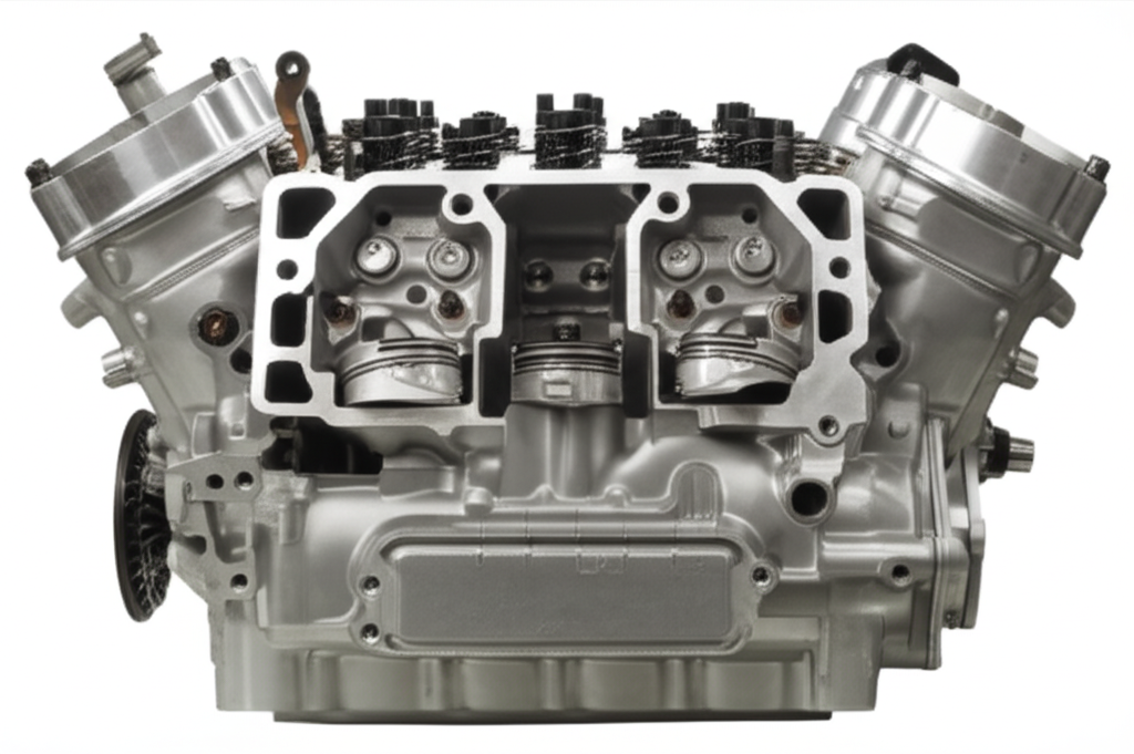
What is a Hemi Motor? Understanding the Iconic Engine—and What It Teaches Us About Motor Laminations
Every engineer hears the question sooner or later. What is a Hemi motor and why do people still talk about it like a legend? If you design powertrain systems or you source components for electric machines you may wonder how a combustion-era icon relates to your world of stators, rotors, and electrical steel. It does. The Hemi story is a case study in how a single design choice controls airflow, power density, packaging, cost, and manufacturability. The same trade-off mindset drives smart decisions about motor laminations for BLDC and AC machines.
Let’s unpack both. We’ll explain what “Hemi” really means. We’ll cover the history, the tech, the pros and cons, and the famous 5.7L, 6.1L, 6.4L, 6.2L Hellcat, and 426 Hemi engines. Then we’ll pivot. You’ll see how the same engineering thinking that made Hemi engines effective will help you choose lamination materials, thickness, and processes that boost efficiency and cut losses in your electric motors.
In short, we’ll go from pistons to laminations without losing the plot.
In This Article
- The Core Concept: What “Hemi” Really Means
- A Brief History of the Hemi Engine
- How Does a Hemi Engine Work? Key Technologies and Design
- Advantages and Disadvantages of Hemi Motors
- Common Hemi Engine Displacements and Their Applications
- Hemi Motor Performance and Reliability
- Is a Hemi Motor Right for You?
- The Future of the Hemi Engine
- From Hemi to Electric: What Motor Laminations Mean for Efficiency and Cost
- Lamination Materials 101: Silicon Steel, CRGO/CRNGO, Cobalt Alloys
- Manufacturing Processes: Stamping vs Laser Cutting vs Bonding vs Interlocking
- Selecting the Right Lamination Approach for Your Application
- Your Engineering Takeaway
The Core Concept: What “Hemi” Really Means
The Hemispherical Combustion Chamber Explained
“Hemi” is short for hemispherical. In engine terms it refers to a hemispherical combustion chamber in the cylinder head. Picture a dome. That shape lets engineers place the intake and exhaust valves on opposite sides and set them at large angles. Air and fuel rush in more directly. Exhaust gases flow out with less obstruction. This design produces excellent airflow and a clean flame front.
Two big engineering wins follow:
- Large valves fit in that dome. Bigger valves move more air which supports high horsepower and torque.
- The spark ignites the mixture near the center of a smooth chamber. The flame propagates efficiently and reduces the chance of hot spots.
Compare that to wedge-head designs. Those are flatter and simpler. They package more easily and they can run lean at part load with advanced turbulence features. They usually don’t match the peak-valve-area potential of a true hemispherical chamber.
A Brief History of the Hemi Engine
Early Aviation & Tank Engines (Pre-WWII)
You can trace the concept to early aviation and tank engines. Engineers liked the hemispherical chamber for the same reasons you do today. It flows well. It burns consistently. Military applications needed power density and reliability under load so the geometry made sense.
The Golden Era: The Original 426 Hemi (1950s–1970s)
Chrysler brought hemispherical heads to American performance with the FirePower V8 in the 1950s. The legend crystallized with the 426 Hemi in the 1960s. Racers nicknamed it the “Elephant” because it was big, heavy, and brutally strong. It dominated NASCAR and drag racing. Plymouth Barracuda and Dodge Charger models with the 426 Hemi wrote themselves into muscle car history. Advertised output hovered around 425 hp and 490 lb-ft yet many engines made more in real-world tune. The 426 Hemi set benchmarks for power and cultural impact that still shape the conversation.
The Modern Resurgence: Third-Generation Hemi (2000s–Present)
Chrysler revived the Hemi idea in the early 2000s with the Gen 3 Hemi architecture. These modern engines used hemispherical chamber themes rather than pure classic geometry. They added modern tricks:
- Multi-Displacement System (MDS) for cylinder deactivation
- Dual spark plugs per cylinder for improved combustion stability
- Digital engine controls and electronic fuel injection (EFI)
The 5.7L Hemi returned brute torque to Ram 1500 trucks and Dodge Charger and Chrysler 300 sedans. The 6.1L Hemi powered SRT-8 models. The 6.4L (392) Hemi stepped up performance again. Then the supercharged 6.2L Hellcat family rewrote the rules with 707 to 840 hp. The third-generation lineup made “Hemi” a household word again.
How Does a Hemi Engine Work? Key Technologies and Design
Hemispherical Cylinder Heads: The Signature Feature
The hemispherical chamber supports large valves and shrouds them less. Engineers can place the intake valve where incoming flow arcs naturally. The exhaust valve sits opposite. With more direct paths the heads flow well. That allows high volumetric efficiency which translates into horsepower.
Multi-Displacement System (MDS): Balancing Power and Efficiency
MDS shuts off fuel and valve operation on certain cylinders under light load. By running fewer cylinders the engine reduces pumping losses and saves fuel during cruise. The ECU monitors load and reactivates the cylinders under demand. It’s a clever trick. It doesn’t turn a V8 into a Prius yet it trims real-world consumption.
Dual Spark Plugs Per Cylinder (Modern Hemi)
Modern Hemi heads often use dual spark plugs per cylinder. One plug would fire the large chamber slowly at low load. Two plugs light the charge from two points which speeds up combustion and can reduce emissions. This helps land a big-bore V8 into tighter emissions windows without sacrificing the signature Hemi engine sound and power delivery.
Pushrod V8 Architecture
The Gen 3 Hemi sticks with overhead valve (OHV) pushrods rather than dual overhead camshafts. That keeps overall engine height in check and uses a compact valvetrain. It trades high-RPM airflow potential for packaging simplicity, low-end torque, and durability. The camshaft sits in the block. Lifters actuate pushrods. Rockers open and close valves.
Advantages and Disadvantages of Hemi Motors
Pros: The Power and Performance Edge
- Excellent airflow from hemispherical chambers
- High horsepower and torque potential
- Robust architecture with strong blocks and bottom ends
- Memorable Hemi engine sound that resonates with enthusiasts
- Proven in drag racing and NASCAR history
Cons: Fuel Economy and Packaging Challenges
- Large cylinder heads create packaging constraints
- The design can run heavier than some alternatives
- Fuel economy trails smaller displacement or high-tech turbo engines in many cases
- Emissions and efficiency targets get harder at scale without electrification support
Common Hemi Engine Displacements and Their Applications
5.7L Hemi V8
The workhorse in Ram 1500, Dodge Charger, Chrysler 300, and Jeep Grand Cherokee. Output typically lands between 345 and 395 hp with 375 to 410 lb-ft. It pairs MDS with dual plugs for a blend of everyday drivability and towing capability.
6.1L Hemi V8 (SRT-8)
An earlier performance step in the 2000s for Challenger, Charger, and 300C SRT-8 trims. It lifted output and helped reset expectations for mass-market V8 performance.
6.4L Hemi V8 (392 Hemi)
The 392 Hemi brought 470 to 485 hp with 470 to 475 lb-ft in many applications. You see it in Scat Pack models and heavy-duty Ram trucks. It provides big displacement grunt without the cost and complexity of forced induction.
6.2L Supercharged Hemi V8 (Hellcat/Demon/Redeye)
This one made the headlines. IHI supercharger on a forged bottom end. Output ranges from 707 to 840 hp with 650 to 770 lb-ft. You find it in the Dodge Challenger and Charger Hellcat and Redeye trims, the Demon drag-special, the Ram 1500 TRX, and the Jeep Grand Cherokee Trackhawk.
The Legendary 426 Hemi (7.0L)
The classic Elephant. Advertised at 425 hp yet known to deliver much more. It dominated racing and cemented the Hemi reputation.
Hemi Motor Performance and Reliability
Horsepower and Torque Figures
- Classic 426 Hemi: 425 hp advertised with ~490 lb-ft
- Modern 5.7L Hemi: roughly 345 to 395 hp and 375 to 410 lb-ft
- 6.4L (392): about 470 to 485 hp and 470 to 475 lb-ft
- 6.2L Supercharged: 707 to 840 hp and 650 to 770 lb-ft
These numbers vary by model year and application. The trend is clear. Hemi engines deliver stump-pulling torque with strong top-end performance.
Common Maintenance & Potential Issues
- Oil type and change intervals matter in any Hemi V8
- Spark plug maintenance doubles with dual-plug heads
- Some 5.7L models experienced MDS lifter and camshaft wear concerns in earlier years
- Supercharged engines require attention to belts, intercooling, and lubrication
Overall Reliability and Lifespan
With proper maintenance the modern Hemi engines have proven robust for daily use. The supercharged family uses strong internals and can live long lives if owners follow service schedules and keep intake air temperatures under control.
Is a Hemi Motor Right for You?
If you want brute power, towing capacity, and a performance driving feel a Hemi checks the boxes. If your priorities lean toward peak fuel economy or a smaller engine footprint a turbocharged six or hybrid might fit better. Engineers and procurement managers also look at total lifecycle cost. Fuel, upkeep, and resale all factor into the decision.
The Future of the Hemi Engine
Electrification changes the landscape. Stellantis has focused on the Hurricane inline-six and on hybrid and EV platforms. Some ask about “electric Hemi motors.” That phrase is more cultural than technical. Electric motors don’t have combustion chambers. The Hemi brand may live on in spirit yet the hardware shifts to batteries and inverters. Performance will still matter. The path to it will change.
Now let’s pivot to your world.
You design or buy electric machines. You care about torque density, thermal performance, noise, and cost. The same rigor that made Hemi engines successful will help you choose lamination materials, thicknesses, and manufacturing processes that cut core losses and raise efficiency.
From Hemi to Electric: What Motor Laminations Mean for Efficiency and Cost
Problem
“How does lamination thickness affect motor efficiency?” “Which electrical steel grade should I specify for a high-frequency BLDC stator?” “What manufacturing process scales best from prototypes to volume?” These are not side questions. They define your motor’s performance, heat rise, and costed BOM. Choose well and your machine runs cooler with less copper usage at the same torque. Choose poorly and you fight eddy current losses, audible noise, and scrap rates.
Explain
Eddy currents are your invisible enemy. Think of a river that meets an obstacle and spins up small whirlpools. A changing magnetic field does the same thing inside a solid steel core. Those circular currents waste energy as heat. They also drive temperature rises that limit torque density. Laminations stop those whirlpools from growing. Thin sheets of insulated electrical steel break the current paths. Each lamination forces eddy currents to die early which slashes loss and heat.
Two core loss mechanisms drive your numbers:
- Eddy current loss: Increases with frequency squared and with lamination thickness squared. Thinner laminations reduce it sharply.
- Hysteresis loss: Magnetic domains flip with each cycle. The material’s coercivity matters. Lower coercivity cuts hysteresis losses.
Magnetic permeability tells you how readily the material channels flux. Picture a sponge soaking up water. High permeability lets flux flow with less magnetizing force which can reduce magnetizing current.
Guide
You have two levers. Material choice and manufacturing process. Material governs intrinsic magnetic behavior and resistivity. Process governs dimensional accuracy, burrs, heat-affected zones, and stacking factor. Together they determine core loss, noise, and cost. For a primer on the building blocks see the overview of motor core laminations.
Lamination Materials 101: Silicon Steel, CRGO/CRNGO, Cobalt Alloys
Material Considerations
- Non-Oriented Silicon Steels (NOES, M-grades): The workhorse for rotating machines. Balanced properties in all directions of the sheet. Common thicknesses near 0.50, 0.35, 0.30, or 0.27 mm. Thinner gauges cut eddy current loss at higher frequency. You source these to IEC 60404 test methods for loss and permeability and to ASTM standards like ASTM A677 that define sheet properties and tolerances.
- Grain-Oriented Silicon Steel (GOES, CRGO): Optimized for one rolling direction. Transformers love it due to low loss along the grain. Rotating machines rarely use CRGO because the flux rotates and sees off-axis properties. For transformer cores and EI/UI stacks CRGO shines.
- Non-Oriented Cold-Rolled Grades (CRNGO): The umbrella for NOES variations. You evaluate core loss at target flux density and frequency. Coatings matter because interlaminar insulation controls shorting in the stack. Coatings must survive your punching or laser cutting process.
- Cobalt Alloys: Premium materials for extreme power density and high frequency. They offer very high saturation flux density which helps minimize core mass and hold torque at high speed. They cost more. You use cobalt when the performance benefit outweighs the price and supply risk.
Key Points for Engineers and Buyers
- Loss vs Frequency: Eddy losses scale with thickness squared and frequency squared. If your BLDC runs with a high electrical frequency you win by going thin.
- B-H Curve and Coercivity: Look at the B-H loop to assess how the material magnetizes and demagnetizes. Lower coercivity means lower hysteresis loss.
- Saturation: High saturation flux density lets you run higher peak flux without saturating which preserves torque and reduces copper oversizing.
- Coatings and Bonding: Coating class controls resistivity and handling. You need a coating that supports your chosen assembly method and that holds up under stress relief.
- Standards and Testing: Rely on IEC 60404 for magnetic property measurement and on relevant ASTM specifications for sheet quality. Ask suppliers for Epstein frame or single sheet tester data at your operating flux density and frequency.
If you want a single page to align your team on terminology and options see this guide to electrical steel laminations.
Manufacturing Processes: Stamping vs Laser Cutting vs Bonding vs Interlocking
Process choices change more than unit cost. They change your losses, noise, and dimensional control. Here’s a balanced view.
Stamping
- Pros: Best for high-volume programs with stable geometry and tight tolerances. High throughput and consistent edge quality when dies are sharp. Interlocking features can snap laminations together like LEGO bricks which raises stiffness without welding.
- Cons: Tooling cost can be significant. Die maintenance matters. Burrs increase core loss and can create partial shorts if coatings break. Stress from punching can raise local losses unless you apply stress relief annealing when required by the grade.
Laser Cutting
- Pros: Ideal for prototyping, low-volume runs, and complex shapes. Zero tooling lead time. Quick design changes with CAD. Excellent for early motor development when slot shapes evolve.
- Cons: Heat-affected zones raise local loss. You can minimize this with parameters and post-processes yet stamping often wins for loss performance at scale. Not the lowest cost beyond small batches.
Wire EDM and Waterjet
- Pros: Precise edges with minimal burr. Useful for sample parts and research.
- Cons: Slow and expensive for production.
Bonding, Interlocking, and Welding
- Interlocking: Small tabs form during stamping and press together during stacking. Works like LEGOs to build rigid stacks and avoids heat input which can degrade magnetic properties.
- Bonding: Adhesive bonding or backlack-coated steel can deliver excellent stacking factor and mechanical stability. You avoid mechanical tabs and you get quieter cores due to damping. You must validate cure processes and compatibility with coatings.
- Welding: Use sparingly. Heat can degrade magnetic properties and raise local loss. If you weld, keep heat input small and away from critical flux paths.
Stacking Factor and Coating Integrity
Stacking factor is the ratio of steel to total stack height. Better stacking factor gives you more active material in a given dimension which can raise torque and lower copper use. Coating integrity prevents lam-to-lam shorts and further reduces eddy losses. Control burr height and inspect stacks for damage to coatings.
For a closer look at specific subassemblies:
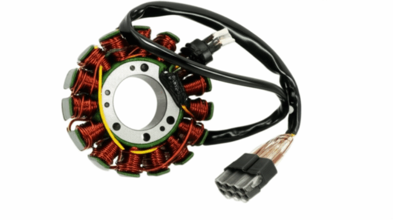
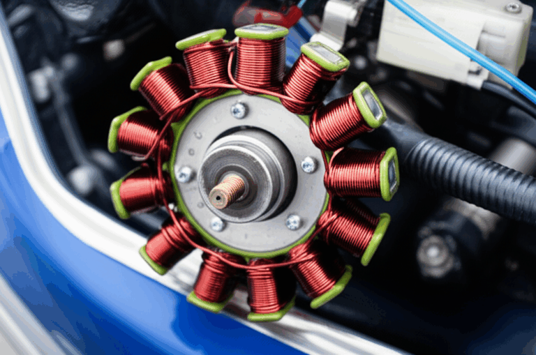
- Stators: Geometry, slot shape, and tooth tips control torque ripple and acoustic noise. Learn more in this overview of stator core lamination.
- Rotors: Skewing strategies and bridge design balance mechanical strength with magnetic performance. See the fundamentals of rotor core lamination.
Selecting the Right Lamination Approach for Your Application
Match design intent to materials and processes. This is where engineers and procurement teams can align.
Low to Mid Frequency General-Purpose Motors
- Material: NOES silicon steel in common M-grades
- Thickness: 0.35 mm or 0.50 mm depending on speed and cost
- Process: Stamping for volume and consistent loss performance
- Assembly: Interlocking or bonding depending on noise targets and environmental exposure
High-Frequency BLDC and Traction Motors
- Material: Premium low-loss NOES or cobalt alloys for extreme power density
- Thickness: 0.27 mm or thinner when the frequency justifies the cost
- Process: Stamping with tight burr control and potential stress relief where needed
- Assembly: Bonded stacks for improved damping and reduced acoustic noise
Prototyping and Early Design Exploration
- Material: Same class you plan to use in production to keep data comparable
- Process: Laser cutting for speed and geometry iteration
- Assembly: Simple bonding or interlocking for quick turn builds
Transformers and Static Machines
- Material: CRGO for low loss along the grain direction
- Geometry: EI or UI shapes to control leakage and simplify assembly
If you focus on BLDC machines, slot design and tooth geometry dominate torque ripple and cogging noise. The lamination stack does the heavy lifting. If you want quick background for your next design review see this summary of a bldc stator core.
Practical Procurement Tips
- Ask suppliers for loss curves at your operating flux density and frequency. Numbers at 50/60 Hz may not predict performance at 400 Hz or higher.
- Request sample stacks built the same way you plan to build production parts. Process history affects loss.
- Validate coating class and adhesion after your cutting and stacking steps. Keep eye on burr height and edge quality.
- Define acceptance criteria for stacking factor, flatness, and skew accuracy if applicable.
Hemi FAQs for Engineers: Quick Hits and Comparisons
Why is it called Hemi?
- The name comes from the hemispherical combustion chamber.
What makes a Hemi special?
- Large valves, good breathing, strong bottom end, and a combustion chamber that supports efficient flame propagation.
Hemi vs other engines like V8 or V6?
- Hemi refers to the chamber shape not the cylinder count. Most famous Hemis are V8s. A V6 can use a Hemi-like chamber yet packaging gets tricky.
Hemi vs Ford Coyote vs GM LS
- Ford’s Coyote uses DOHC with four valves per cylinder and variable cam timing which breathes well at high RPM. GM’s LS/LT pushrod V8s optimize compact package and efficiency with advanced combustion. Hemi focuses on hemispherical flow and torque. Each architecture trades complexity, cost, and packaging differently.
Hemi engine horsepower and torque
- See the ranges above. The Hellcat family redefined factory output for mass-produced cars.
Hemi engine technology today
- MDS cylinder deactivation, dual spark plugs, EFI, and variable valve timing on some variants.
Hemi engine maintenance and problems
- Routine oil and plug changes. Watch for MDS lifter and cam wear on certain years of the 5.7L. Supercharged models need belt and intercooler care.
Is a Hemi a good engine?
- Yes when you prioritize performance, towing, and durability. Fuel economy can lag smaller or hybrid powertrains.
Cars and trucks with Hemi engines
- Dodge Challenger and Charger, Chrysler 300, Ram 1500, Jeep Grand Cherokee, Dodge Durango, and performance halo models like Demon and Redeye.
Why bring up all these details in a lamination article?
- Because good engineering is pattern recognition. The Hemi debate is about design geometry, airflow, and trade-offs. Your motor lamination decisions follow the same path. Choose the right geometry, material, and process for your target performance and cost.
Your Options in Context: Bringing It All Together
You now see the parallel. The Hemi’s hemispherical combustion chambers unlocked airflow and power with a clear trade-off in packaging and efficiency. Motor laminations do the same thing in your world. Laminations unlock high efficiency and thermal stability by driving down eddy current losses. You still make trade-offs. Thin material costs more. Bonding adds process steps. Stamping dies require capital yet deliver low piece price and consistent loss performance.
If your application leans toward traction duty or high-speed BLDC control focus on:
- Low-loss NOES at your operating frequency
- Thin gauges to minimize eddy losses
- Bonded stacks to reduce acoustic noise and lamination buzz
- Tight process control on burrs and coating integrity
If you support general-purpose AC machines for pumps or fans you may optimize for:
- Stable supply of mid-grade NOES
- 0.35 mm thickness that balances cost and loss
- Proven stamping and interlocking designs that scale well
You can dive into subassembly best practices any time using these primers on stator core lamination and rotor core lamination. If you need a refresher on the material landscape check the overview of electrical steel laminations.
Trust Signals: Standards and Data You Can Ask For
When you speak with suppliers or evaluate quotes ask for:
- Magnetic loss data per IEC 60404 test methods at your target flux density and frequency
- B-H curves to understand saturation and coercivity
- Coating specifications including insulation class and cure requirements
- Stack flatness and stacking factor acceptance criteria
- Evidence of stress relief or equivalent process controls if your design requires it
- For transformers confirm GOES grades and core building method for EI or UI stacks
For rotating machinery you can also request finite element analysis (FEA) of flux paths and hotspot predictions. If you plan to switch from laser-cut prototype laminations to production stamping you should validate loss deltas early to avoid surprises.
Your Engineering Takeaway
- Hemi 101: “Hemi” means hemispherical combustion chambers. The design supports large valves and efficient flame travel which drives power and torque. Classic 426 Hemi engines and modern 5.7L, 6.1L, 6.4L, and 6.2L Hellcat variants deliver big numbers with clear packaging and efficiency trade-offs.
- Core design lesson: Geometry matters. The right shape unlocks performance and sets constraints on packaging and cost.
- Motor laminations matter more than you think: Thinner insulated laminations reduce eddy current losses and cut heat. That raises efficiency and power density.
- Material selection drives performance: NOES silicon steels fit most rotating machines. CRGO excels in transformers. Cobalt alloys serve extreme high-frequency or high-density designs.
- Process defines real-world results: Stamping dominates in volume. Laser cutting fits prototypes and low volume. Bonding and interlocking build rigid, quiet stacks without the magnetic penalties of welding.
- Match approach to application: High-frequency BLDC machines benefit from thin-gauge low-loss material and bonded stacks. General-purpose motors can use thicker gauges and interlocking with good results at lower costs.
- Ask for the right data: IEC 60404 test results at your operating flux density and frequency. B-H curves. Coating specs. Stacking factor. Burr height. Validate prototype-to-production transitions.
Next steps
- Define your operating frequency, flux density, and temperature targets.
- Shortlist materials based on loss curves and saturation limits.
- Choose a manufacturing route that fits your volume and noise goals.
- Request prototype stacks that mirror your production intent.
- Schedule a technical call with a lamination supplier to review drawings, tolerances, and coating requirements. Bring loss curves and slot geometry questions to the table so you get actionable feedback.
If you want a concise overview to share with your team use these resources on motor core laminations, stator core lamination, rotor core lamination, electrical steel laminations, and a focused summary for a bldc stator core. They will help you align on terminology and trade-offs before you place your next RFQ.
Finally, if you came here for the original question. What is a Hemi motor? It’s an engine family built around hemispherical combustion chambers that delivered iconic power and racing success. If you stayed for the lamination guidance you already know the bigger point. Thoughtful geometry and material choices win. Whether you tune a 6.4L 392 Scat Pack or you optimize a high-speed BLDC with low-loss laminations the engineering process looks the same. Define the physics. Compare the options. Pick with intent. Then build with discipline.

