What is a DC Motor? Understanding Direct Current Motors
Every engineer has asked the same question at one point. What exactly is a DC motor, how does it work, and which design decisions really move the needle on performance and cost? If you design products with electric motion or you source motor components, you live in a world of trade‑offs. Speed control vs. efficiency. Torque density vs. heat. Simplicity vs. lifetime. The choices you make around laminations, materials, windings, and commutation ripple through torque‑speed characteristics, power losses, noise, and total cost of ownership.
Here’s the good news. You can simplify this decision space with a clear grasp of DC motor fundamentals and a practical understanding of motor laminations. You’ll see where the losses come from, why stator and rotor laminations matter, and how to choose materials and processes that fit your application. We’ll walk you through the basics of brushed and brushless DC motors, then dig into lamination materials, thickness, and manufacturing. You’ll leave with a short list of next steps you can act on today.
In This Article
- The Core Definition: What Does DC Motor Mean?
- How Does a DC Motor Work? The Principle of Operation
- Key Components of a DC Motor
- Why Laminations Matter in DC Motors
- Types of DC Motors
- Advantages and Disadvantages of DC Motors
- Common Applications of DC Motors
- DC Motors vs. AC Motors: A Quick Comparison
- Material Considerations for Laminations
- Manufacturing and Assembly Processes for Laminations
- Which Application Is This For? Matching Choices to Use Cases
- Sizing and Control Basics: Voltage, Current, PWM, and H‑Bridges
- Reliability, Maintenance, and Procurement Considerations
- Conclusion: Your Engineering Takeaway
The Core Definition: What Does DC Motor Mean?
A DC motor is an electromechanical device that converts electrical energy from direct current into mechanical energy as rotational motion. Direct current means voltage and current flow in one direction rather than alternating. The motor uses electromagnetic principles to generate torque on a rotor that spins inside a magnetic field.
You meet DC motors everywhere. Power windows and wipers in vehicles. Conveyor drives in industrial automation. Robotics joints. Drone propulsion. Cordless power tools. Fans and pumps. From micro DC motors in toys to high torque DC motors for traction, the same backbone applies. Current in conductors interacts with a magnetic field and produces force. Torque builds. The shaft turns. Useful work comes out.
How Does a DC Motor Work? The Principle of Operation
Electromagnetism in Action
When current flows through a conductor in a magnetic field, it experiences a force. This is the Lorentz force. In a DC motor, that conductor lives in the rotor winding or armature winding. The stator provides the magnetic field using permanent magnets or a field winding. The interaction creates torque proportional to magnetic flux and armature current.
Faraday’s law explains the flip side. A moving conductor in a magnetic field induces a voltage. As the rotor spins, it generates a counter voltage called back EMF. Back EMF opposes the supply and rises with speed. It’s why a DC motor draws high current at start then settles as speed increases. It’s also why speed control works so well with DC motors using voltage or PWM motor control.
Continuous Rotation Explained
The stator is stationary. It provides a steady magnetic field. The rotor spins. It carries coils positioned to see the field. To keep torque in the same direction, the current in each armature coil must reverse at the right time. Brushed DC motors use a commutator and carbon brushes to switch current mechanically. The commutator acts like a rotary switch. Brushes feed current into the correct coil segments as the rotor turns. That switching keeps torque unidirectional and continuous.
Brushless DC motors, or BLDC motors, remove the brushes and commutator. They use electronic commutation instead. Hall effect sensors or sensorless control detect rotor position. A motor controller then switches current in the stator phases to pull the rotor around. Efficiency rises. Mechanical wear drops. Speed control improves under load.
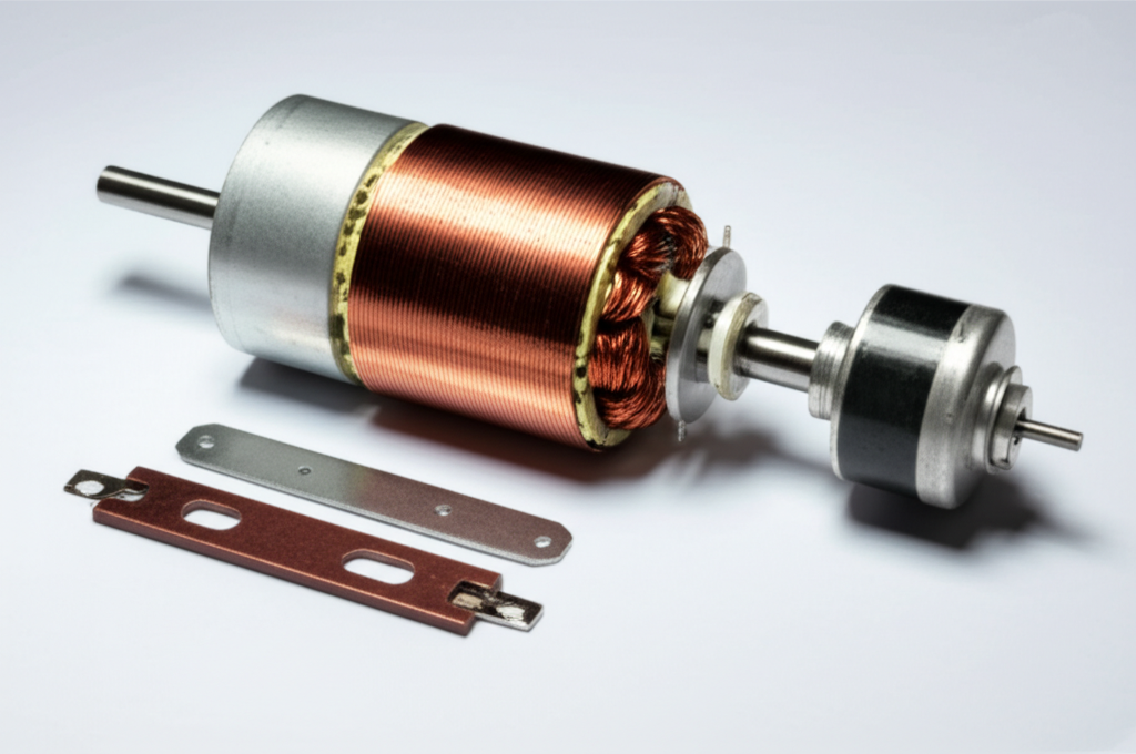
Key Components of a DC Motor
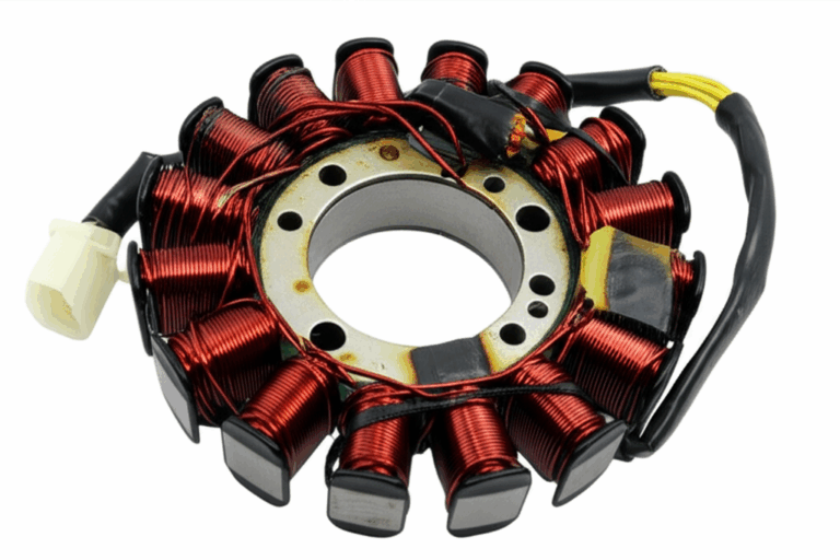
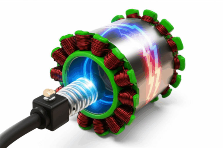
- Stator: The stationary magnetic circuit. It uses permanent magnets or field windings to generate the main magnetic field. In both brushed and brushless motors, the stator core is built from thin steel laminations to control eddy currents and hysteresis loss. For a deeper dive on stator construction see the role of stator core lamination.
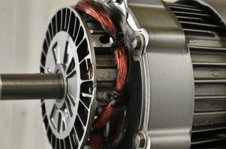
- Rotor (Armature): The rotating part that carries conductors. In a brushed DC motor, the armature has coils wound in slots in a laminated core. In a BLDC motor, the rotor often carries permanent magnets while the stator is wound. Rotor cores also rely on thin laminations to manage core losses at electrical frequency harmonics and mechanical speed. Learn more about the considerations behind rotor core lamination.
- Commutator: A segmented copper cylinder on the rotor shaft. It reverses current direction in the armature coils as the rotor spins so torque stays in the same direction.
- Brushes: Carbon or graphite blocks that conduct current from stationary leads to the rotating commutator. They wear over time and introduce electrical noise and occasional sparking.
- Shaft and Bearings: The mechanical output line for torque and speed. Bearings keep radial and axial loads in check and set expectations for service life.
- Frame and Endbells: Structural parts that align the magnetic circuit, protect the windings, and manage cooling paths.
Why Laminations Matter in DC Motors
Eddy currents and hysteresis are the villains in your core loss story. Picture a river with large whirlpools. Those are eddy currents. You don’t want them because they waste energy as heat. When a magnetic field changes in a bulk steel core, it induces circulating currents inside the metal. Thinner, insulated laminations break up those large whirlpools into tiny swirls that can’t go far. The electrical insulation between sheets blocks current flow across layers. Eddy current loss falls with lamination thickness squared at a given frequency. So halving thickness can cut eddy loss dramatically.
Hysteresis loss is different. Magnets don’t flip direction for free. It takes energy to cycle a magnetic material through its B‑H curve. Materials with lower coercivity, which is resistance to demagnetization, exhibit lower hysteresis loss. Grain orientation and alloying elements like silicon tweak this behavior. Better materials cost more yet they pay back at higher speeds or higher switching frequencies.
Why this matters to you:
- Thinner laminations lower core loss at higher electrical frequencies. You’ll see cooler operation and higher efficiency.
- Better insulation coatings reduce interlaminar eddy currents and improve stacking factor.
- Clean cutting with minimal burrs preserves insulation and avoids shorted turns between sheets.
- Stress relief annealing after punching can restore magnetic permeability if the process work‑hardens the edges.
- Sophisticated bonding or interlocking methods keep stacks rigid without excessive welding heat input that can degrade properties.
You can hit your efficiency target with the right combination of lamination thickness, alloy, and process. You can also shave manufacturing waste and improve consistency.
Types of DC Motors
Brushed DC Motors
- Permanent Magnet DC (PMDC): Uses permanent magnets in the stator and a wound armature. Simple. Compact. Great for small DC motors and consumer applications. Speed control is straightforward using voltage or PWM.
- Series Wound DC Motor: Field winding in series with armature current. Delivers high starting torque and is common in starter motors and traction applications. Speed varies strongly with load.
- Shunt Wound DC Motor: Field winding in parallel with the armature. Provides good speed regulation under load and suits industrial drives and machine tools.
- Compound Wound DC Motor: Combines series and shunt fields for a balance of starting torque and speed regulation.
All brushed types bring brush wear, electrical noise, and sparking at the commutator. They also offer a simple control scheme and low initial cost.
Brushless DC Motors (BLDC)
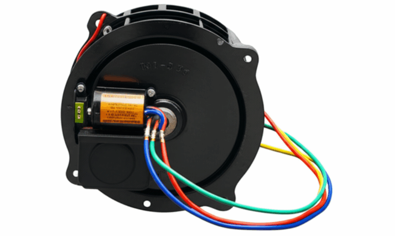
BLDC motors eliminate brushes and use electronic commutation. The stator carries three‑phase windings. The rotor carries permanent magnets, often neodymium for high torque density. A controller drives an H‑bridge or inverter to sequence current based on Hall effect sensors or sensorless back EMF detection. BLDC motors achieve higher efficiency, longer lifespan, and better speed control. They cost more upfront due to the controller and magnets.
If you’re designing a drone, robot joint, or small EV traction module, you’ll likely care about stator architecture and slot geometry in the BLDC core. For practical insights and examples of stacks and tooth shapes see a typical bldc stator core.
Other Notable DC Motor Varieties
- Coreless DC Motor: Uses a self‑supporting coil without an iron core in the armature. Inertia drops. Acceleration jumps. Ideal for small precision devices.
- Gear DC Motor: Integrates a gearbox with a DC motor to trade speed for torque. Common in robotics and automation.
- Servo Motor: Often DC or BLDC inside. Adds feedback and control electronics for precise position, speed, and torque control.
- Stepper Motor: Operates with DC through step sequences, though it behaves differently. It moves in discrete steps rather than continuous rotation without microstepping.
Advantages and Disadvantages of DC Motors
Advantages
- Excellent speed control with voltage or PWM. You can dial in RPM precisely.
- High starting torque, especially with series wound designs.
- Simple construction and low cost for brushed types.
- Easy to reverse direction with an H‑bridge motor driver.
- Predictable torque‑speed characteristics and linear relationships across practical ranges.
Disadvantages
- Brushes wear. Maintenance becomes a factor for brushed motors.
- Sparking and electrical noise can interfere with sensitive electronics.
- Efficiency lags BLDC in many ranges due to brush friction and commutation losses.
- Commutation limits max speed and power in brushed motors.
- Controller complexity and magnet cost raise BLDC initial investment.
Common Applications of DC Motors
- Automotive: Power windows, windshield wipers, seat actuation, fuel pumps, HVAC blowers, and the classic series DC starter motor.
- Robotics and Automation: Industrial robots, collaborative robots, drones, AGVs. BLDC dominates where precision and efficiency matter.
- Consumer Electronics: Toys, CD/DVD drives, cooling fans, electric toothbrushes, small pumps.
- Power Tools: Cordless drills, saws, grinders, and garden tools.
- Medical Devices: Infusion pumps, surgical tools, dental handpieces that need high speed.
- Electric Vehicles: Traction motors, often BLDC or permanent magnet synchronous types. DC power electronics still handle battery interfaces, regenerative braking, and low‑voltage auxiliaries.
- Industrial Machinery: Conveyors, small machine tools, positioning stages, and pumps.
Market reports peg the global DC motor market around the mid‑tens of billions of dollars with steady growth. Automotive and industrial automation hold a significant share, and BLDC adoption keeps climbing due to efficiency mandates and battery powered platforms.
DC Motors vs. AC Motors: A Quick Comparison
Both families excel in different lanes. DC motors shine when you need fine speed control and high starting torque with simple controls. AC motors dominate in grid‑connected industrial power with VFDs and low maintenance.
Material Considerations for Laminations
Your lamination material sets the magnetic ceiling and the loss floor. Get this right first.
- Silicon Steels (Non‑Oriented Electrical Steel, often M‑grades): The workhorse. Silicon reduces hysteresis loss and increases resistivity, which cuts eddy current loss. Non‑oriented grades serve motors with rotating flux because their properties are similar in all directions. Thinner gauges improve performance at higher electrical frequencies. These steels come with insulation coatings that stand up to punching and stacking. See typical options and uses in electrical steel laminations.
- Grain‑Oriented Steels (CRGO): Optimized for one direction of flux and used extensively in transformers. Motors see rotating fields, so CRGO does not fit well.
- Cobalt‑Iron Alloys: High saturation flux density and excellent permeability. You can push power density higher and shrink the machine. Cost climbs and manufacturability tightens. You’ll see these in aerospace and high performance traction.
- Low‑Loss High‑Silicon Steels: Proprietary formulations deliver very low core loss at mid to high frequencies. Ideal for BLDC motors that switch at tens of kilohertz and run hot if you get the lamination choice wrong.
- Amorphous and Nanocrystalline Metals: Fantastic for transformer cores at high frequencies. Motors impose mechanical stresses, slots, and rotating fields that make these materials tricky. Use with caution and expect premium cost and specialized processes.
What about magnets? Permanent magnet materials for DC and BLDC motors include neodymium iron boron and ferrite. Neodymium magnets yield very high torque density and compact rotors. Ferrite magnets cost less and tolerate higher temperatures in some cases. Magnet choice affects flux density, demagnetization risk, and torque ripple. Match magnets to your stator tooth geometry and lamination thickness to avoid saturation and to control magnetic flux density under load.
Manufacturing and Assembly Processes for Laminations
Process choices change magnetic properties, dimensional control, and cost per part. Pick with your volume, tolerance, and performance targets in mind.
- Stamping and Progressive Die Punching: High volume champion with low per‑part cost and tight repeatability. Watch for burrs and edge work‑hardening that can degrade insulation and permeability. Deburr and consider stress relief annealing to recover properties if needed.
- Laser Cutting: Ideal for prototypes, low‑volume runs, and complex geometries. No hard tooling, quick iteration, and high precision. Thermal effects can raise local hardness and loss if parameters run hot. Tune power and speed, and use post‑process annealing when required.
- Wire EDM: Superb edge quality without burrs. Slower and costlier than laser or stamping. Consider for precision rotors and R&D where edge integrity is critical.
- Waterjet: No heat‑affected zone. Kerf width and taper can be a challenge for thin laminations.
- Stack Assembly Methods:
- Interlocking tabs form mechanical bonds like LEGO bricks that avoid weld heat.
- Bonding with organic resins or adhesives delivers high stacking factors and low vibration. Good for noise sensitive BLDC systems.
- Welding secures stacks for high mechanical loads, though heat can degrade local magnetic properties if uncontrolled. Keep welds away from active flux paths where possible.
- Riveting works for selected geometries and service conditions.
- Insulation Coatings: Choose coatings for electrical resistivity, punchability, thermal class, and chemical resistance. They must survive winding, pressing, and varnishing. They also set interlaminar shear strength.
- Stress and Annealing: Cutting induces residual stresses. Stress increases hysteresis loss and lowers permeability. Proper annealing can restore the BH curve response closer to virgin material.
You build torque with magnetic flux. You keep temperature in check by managing core loss. You improve lifetime with tight stack integrity and consistent insulation.
Which Application Is This For? Matching Choices to Use Cases
- High‑Frequency BLDC for Drones and Robotics: You face high switching frequencies from electronic commutation. Select thin gauge low‑loss non‑oriented silicon steel and consider bonded stacks that reduce vibration. Watch demagnetization margins for neodymium magnets at elevated temperature. Design for good airflow to keep bearings and windings cool.
- Automotive Auxiliary Drives and HVAC DC Motors: Cost and noise matter. Stamping with good deburring hits the sweet spot. PMDC motors benefit from robust commutator design and brush materials that reduce sparking and EMI. Shunt wound DC motors deliver steady speed for fans and blowers.
- Industrial DC Drives and Gear Motors: Torque at low speed may push you toward gear motors with strong interlocked stacks. Rugged insulation coatings help with varnish impregnation. If you need high duty cycles, evaluate BLDC to raise efficiency and cut maintenance.
- High Power Density EV Traction and Aerospace: Cobalt‑iron alloys or advanced low‑loss steels can unlock smaller packages and higher continuous torque. You’ll likely choose BLDC with field oriented control and tightly managed back EMF. Consider dynamic braking and regenerative braking strategies early, since core losses during regen can become the thermal pinch point.
- Prototyping and Custom Motors: Laser cut or wire EDM laminations let you test slot shapes and tooth tips quickly. Bonded stacks will keep acoustic noise down for lab work. Transition to stamping for production once geometry stabilizes.
Honesty about limits builds trust. Laser cutting excels in speed and flexibility for prototypes. It cannot beat stamping for high volume cost and throughput. Bonded stacks look great for noise and efficiency. They require process control and cure cycles that add time.
Sizing and Control Basics: Voltage, Current, PWM, and H‑Bridges
A few control fundamentals anchor good design and sourcing decisions.
- Voltage and Current: Rated voltage and rated current define the nominal operating point. At no load, speed sits near the no‑load speed which follows applied voltage minus back EMF. As load torque rises, current rises and speed drops along the torque‑speed curve.
- Back EMF: Proportional to speed and flux. It limits current naturally as speed climbs. It also enables sensorless BLDC control by observing zero crossings.
- PWM Motor Control: Pulse width modulation applies a fast switching waveform that creates an average voltage at the motor terminals. PWM reduces losses in the controller compared to linear voltage control. It also shapes current ripple in the windings. Set PWM frequency high enough to avoid audible noise with brushed motors. BLDC controllers often switch at tens of kilohertz.
- H‑Bridge Motor Driver: This four‑switch circuit lets you drive a brushed DC motor forward and reverse with braking modes. It enables bidirectional motor control, dynamic braking DC motor strategies, and current limiting. For BLDC, a three‑phase inverter performs the equivalent function.
- Hall Effect Sensors and Sensorless BLDC: Sensors feed rotor position to the controller for precise commutation timing. Sensorless BLDC uses back EMF detection to infer position. It saves cost and simplifies assembly, though low speed torque control gets trickier.
- Torque‑Speed Characteristics: Expect a roughly linear relationship for brushed motors between torque and speed under constant voltage. Starting torque depends on armature design and field strength. Continuous torque depends on thermal limits. Torque production in DC motors scales with current and magnetic flux.
- Dynamic and Regenerative Braking: Dynamic braking dissipates kinetic energy as heat in a resistor or the windings. Regenerative braking DC motor control returns energy to the supply or battery if your system supports it. BLDC and PMDC drives can both exploit regen with the right electronics.
- Thermal Design: Copper loss scales with current squared. Core loss scales with electrical frequency and material. Keep an eye on both. Use thermal paths from the stator to the frame. Ventilation helps in open designs. Potting compounds and varnish improve heat conduction and mechanical integrity.
- Noise and EMI: Brushed motors produce electrical noise and sparks. BLDC switching creates high dV/dt edges that radiate. Good cable routing, grounding, and filtering keep compliance on track. Choice of lamination bonding or interlocking impacts mechanical hum.
Reliability, Maintenance, and Procurement Considerations
Brushed DC motor maintenance revolves around brush wear, commutator condition, and bearing life. You can expect thousands of hours of service for many designs. BLDC motors extend life into the tens of thousands of hours as brush wear disappears and bearings become the primary limit.
For procurement managers and product owners:
- Specify Lamination Details: Thickness, grade, insulation class, stacking method, and allowable burr height. You’ll get more consistent performance and fewer surprises in core loss and efficiency.
- Ask for Material Certifications: Mill certs for silicon steel grades, coating type, and thickness. Request annealing details when applicable.
- Validate Magnetic Properties: Epstein frame testing and single sheet testers measure core loss and permeability. IEC 60404 and ASTM A343 describe accepted methods. Reference them in your drawings and quality plans.
- Control Manufacturing Variables: Cutting method, die condition, burr removal, and handling procedures affect interlaminar insulation. Stack alignment and pressure influence stacking factor and vibration.
- Prototype Early With Production‑Intent Methods: Laser cut prototypes are fast. If your final path is stamping, build samples from stamped laminations before locking specs.
- Think About Supply Chain: For BLDC designs, secure neodymium magnet availability and plan for temperature grade selection. Watch long lead times on specialized cobalt alloys.
- Total Cost of Ownership: BLDC often costs more upfront. It wins over the life of the product with higher efficiency, lower heat, and reduced maintenance. That matters for battery powered systems and sealed devices.
Conclusion: Your Engineering Takeaway
Let’s boil it down.
- A DC motor converts DC electrical energy into mechanical rotation using electromagnetic forces. Brushed motors use mechanical commutation. BLDC motors use electronic commutation.
- Laminations are not a footnote. They set your efficiency floor and thermal ceiling. Thinner, well insulated laminations reduce eddy current loss. Better alloys and stress control reduce hysteresis loss.
- Material choice drives performance. Non‑oriented silicon steel fits most DC motors. Low‑loss thin gauges help at higher switching frequencies. Cobalt‑iron raises torque density when budgets support it.
- Manufacturing matters. Stamping rules high volume. Laser and EDM shine for prototypes and complex shapes. Manage burrs, insulation, and stress. Choose bonding, interlocking, or welding with an eye on magnetic performance and noise.
- Control strategies shape behavior. PWM and H‑bridge drivers deliver precise speed and torque in brushed motors. BLDC with sensors or sensorless control gives you high efficiency and long life.
- Match the approach to your application. Drones and robotics need low‑loss BLDC stators and careful thermal design. Automotive auxiliaries favor cost and noise control. Industrial drives can win with BLDC efficiency and reduced maintenance.
Actionable next steps:
1) Define your electrical frequency and speed range. That informs lamination thickness and alloy selection.
2) Specify lamination details on drawings. Include grade, gauge, insulation coating, and stacking method. Call out acceptable burr height and require post‑cut annealing when needed.
3) Prototype with the cutting process you’ll use in production, or at least validate with a stamped sample before release.
4) Request core loss and permeability data tied to recognized standards like IEC 60404 or ASTM A343. Use those values in your thermal and efficiency models.
5) If you’re evaluating BLDC stator designs, review slot geometry, tooth tips, and winding fill. Confirm magnet temperature grades and demagnetization curves for your duty cycle.
When you are ready to discuss options for stator and rotor stacks, material grades, or bonding vs. interlocking choices, review typical constructions for stator core lamination, compare edge quality and stack integrity in rotor core lamination, and browse representative electrical steel laminations. If your roadmap includes high efficiency BLDC designs, explore the geometry and stack choices in a bldc stator core.
By focusing on lamination materials and processes with the same rigor you bring to windings and controls, you’ll raise motor efficiency, lower operating temperature, and extend service life. You’ll also enter supplier conversations with clarity and confidence, which saves time and money.