What Is a 3 Phase Motor? The Definitive Guide From Someone Who Works With Them Every Day
Table of Contents
- Introduction: Why 3 phase motors matter
- The basics: Single phase vs three phase power
- How a 3 phase motor works: The rotating magnetic field in plain English
- Key components inside a 3 phase motor
- Why choose a 3 phase motor: Advantages that show up on the job
- 3 phase vs single phase motors: A quick comparison you can use
- Types of 3 phase motors: Induction and synchronous
- Common wiring and connections: Wye, delta, and phase sequence
- Starting and control: DOL, star-delta, soft starters, and VFDs
- Motor ratings and nameplate basics: Voltage, frequency, HP, kW, and more
- Power quality and efficiency: Power factor, harmonics, and IE classes
- Installation and safety: What I check before I energize
- Maintenance, troubleshooting, and predictive checks
- Applications you’ll see in the real world
- Selecting the right 3 phase motor for your job
- Costs, lifespan, and total cost of ownership
- Frequently asked questions I hear all the time
- Conclusion: The unsung workhorse of modern industry
Introduction: Why 3 phase motors matter
I still remember the first plant tour I took as a junior tech. I walked past a line of pumps humming along without drama and my mentor whispered, “That sound is money getting made.” He meant the motors. Most of them were 3 phase motors. They moved water and air. They drove conveyors and mixers. They lifted elevators and spun compressors. You don’t notice them until one stops. Then you notice everything.
If you’re asking “What is a 3 phase motor?” you’re in the right place. I’ll explain how these motors work, why they beat single phase motors in most industrial jobs, what’s inside them, and how to pick and care for them. I’ll keep it practical. I’ll use simple language. I’ll share what I’ve learned on job sites and in troubleshooting trenches.
The basics: Single phase vs three phase power
Before we pop the end bell off and look inside, let’s talk about the power supply.
- Single phase AC power uses one alternating voltage waveform. That’s what you see in most homes. It’s fine for light loads like fridges or fans. Many single phase motors need capacitors or auxiliary windings to start because the torque pulses.
- Three phase AC power uses three voltage waveforms spaced 120 electrical degrees apart. This creates a balanced system with a more constant power flow. The torque comes out smooth. The motor starts by itself. That simple difference changes everything.
In my experience, once loads get bigger than a few horsepower, three phase wins on efficiency, torque quality, and reliability. That’s why industrial electric motors are mostly three phase.
How a 3 phase motor works: The rotating magnetic field in plain English
When I teach apprentices, I use a simple image. Picture three people standing around a table. Each one takes a turn pushing a lazy Susan 120 degrees apart in time. The dish keeps spinning smoothly because the pushes come in sequence. That’s what the stator does to the rotor.
Here’s the sequence inside the motor:
- The stator has three sets of windings arranged around the frame. Each set connects to one phase of the supply.
- Three phase current flows through those windings. The three AC waves are offset by 120 degrees.
- This creates a rotating magnetic field in the stator. We call it an RMF for short.
- In an induction motor, that RMF sweeps past the rotor bars and induces current in them. That’s electromagnetic induction in action.
- The induced current in the rotor interacts with the stator’s magnetic field. The Lorentz force produces torque. The rotor begins to chase the rotating field.
- The rotor never quite catches up in an induction motor. The difference in speed is called slip. Slip makes induction happen. No slip means no induced current.
In a synchronous motor the rotor locks to the rotating magnetic field at synchronous speed. The rotor might use DC excitation or permanent magnets. That gives you fixed speed under steady load which can be a big deal for some processes.
Key components inside a 3 phase motor
I’ve pulled apart dozens of motors. The guts don’t lie. Quality parts run cooler and longer.
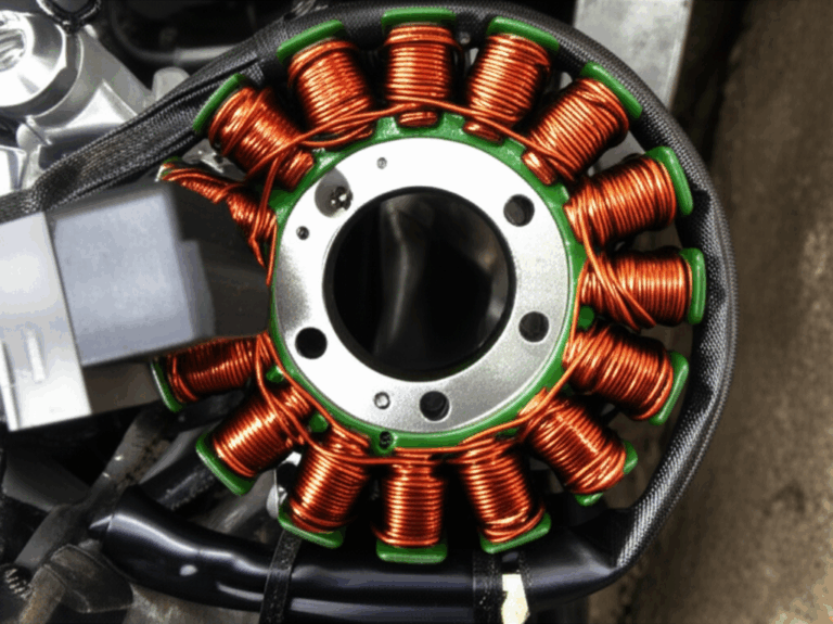
- Stator: The stationary part. It includes the frame, the core, and the windings.
- The core uses insulated steel laminations to cut eddy currents and losses. If you want to dig deeper into how the stack is built the pages on stator core lamination and motor core laminations are helpful.
- The windings use copper or sometimes aluminum.
- Rotor: The rotating part on the shaft.
- Squirrel cage rotor: Cast aluminum or copper bars shorted by end rings. Rugged and common.
- Wound rotor: Three windings connected to slip rings and external resistors for high starting torque.
- Those rotor stacks also rely on steel laminations. See rotor core lamination for how laminations influence loss and performance.
- Bearings: Ball or roller bearings support the shaft. Bearing quality drives noise, vibration, and lifespan.
- End shields or end bells: They hold the bearings and close the frame.
- Cooling fan: Mounted on the shaft. Moves air over the frame. Some motors use separate blowers.
- Terminal box: Houses the lead connections and sometimes the changeover links for delta or wye connections.
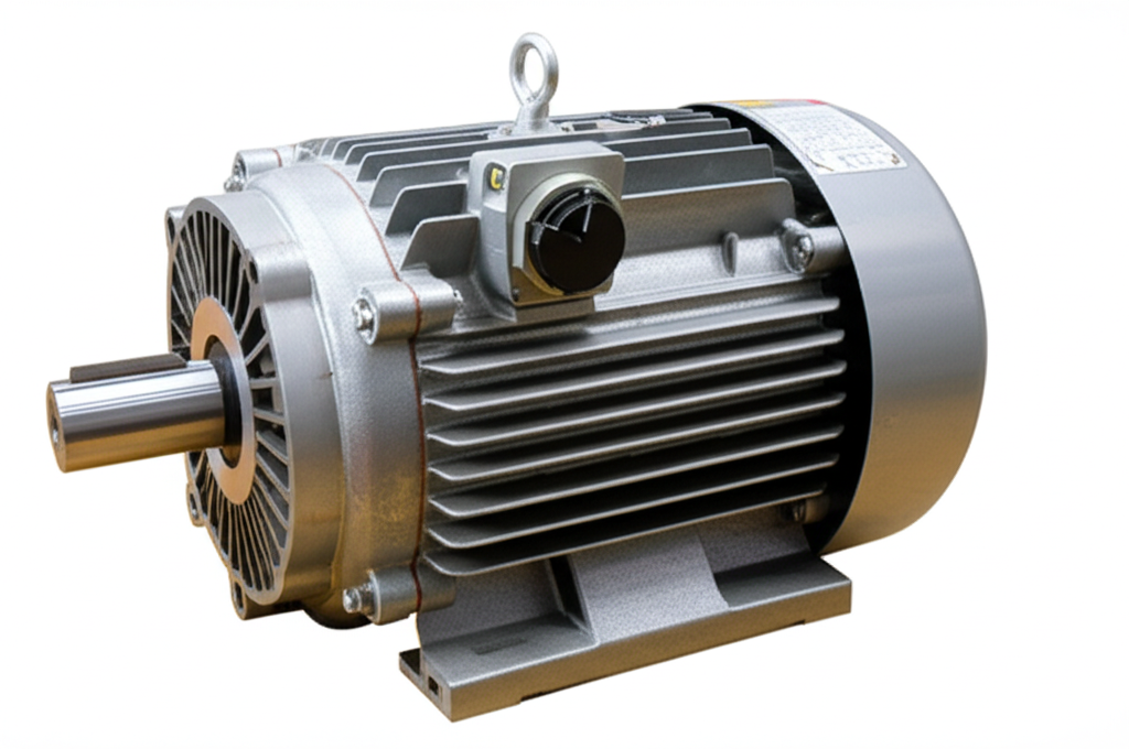
- Frame and enclosure: NEMA or IEC sizes. Enclosures include open drip proof (ODP), totally enclosed fan cooled (TEFC), washdown, explosion proof, and IP rated options.
- Insulation class: Tells you the thermal endurance of the winding insulation. Common classes include Class F or Class H.
- Nameplate: Your truth source. It lists voltage, frequency, horsepower, kilowatt, power factor, current draw, efficiency, service factor, duty cycle, and design letter.
Why choose a 3 phase motor: Advantages that show up on the job
I’ve seen 3 phase motors save headaches in several ways.
- Higher efficiency: You get more mechanical power from the same electrical input. Less heat. Lower energy consumption.
- Constant torque output: Three overlapping phases smooth the torque ripple. The shaft doesn’t pulse under steady load. That reduces vibrations and noise.
- Increased power density: More power from a similar frame size.
- Self starting: No start capacitor or start winding. Energize it and it spins.
- Reliability and durability: Fewer parts prone to failure. Simple and robust.
- Lower maintenance: Bearings and basic checks go a long way. No start switches to burn out like many single phase designs.
- Better for variable speed control: Pair a 3 phase motor with a VFD and you get wide speed control with high efficiency.
3 phase vs single phase motors: A quick comparison you can use
I keep this comparison in my pocket when someone asks if they can “get by” with single phase.
- Power source: Single phase uses one AC waveform. Three phase uses three offset waveforms.
- Starting mechanism: Many single phase motors need start capacitors and switches. Three phase motors start on their own.
- Efficiency and torque: Three phase motors tend to be more efficient. They deliver smoother torque with less pulsing.
- Applications: Single phase works for small residential or light commercial loads. Three phase dominates industrial and heavy commercial loads.
- Cost: A 3 phase motor can cost more upfront. It often costs less to run over the life of the system because of efficiency and maintenance.
Types of 3 phase motors: Induction and synchronous
You’ll encounter two big families.
Induction motors (asynchronous)
- Squirrel cage induction motor: This is the workhorse. It’s rugged and cost effective. The rotor has bars like a cage. It’s great for pumps, fans, conveyors, and compressors.
- Wound rotor induction motor: The rotor has windings connected to slip rings. You can add external resistance to tune starting torque and current draw. I’ve used these on cranes and hoists where high starting torque matters.
Synchronous motors
- The rotor runs at synchronous speed. It locks to the rotating magnetic field. I’ve seen these used in applications that need constant speed regardless of load changes. They can also help with power factor correction when properly excited.
Common wiring and connections: Wye, delta, and phase sequence
Three phase motors can wire in two common ways.
- Wye (star) connection: Ends of the windings join at a common point. You connect the three phase lines to the other ends.
- Delta connection: Windings connect end to start in a triangle. The three phase lines connect at each corner.
Why it matters:
- Voltage per winding changes with connection. A dual voltage motor might use delta for low voltage and wye for high voltage. Check the nameplate and wiring diagram in the terminal box.
- Star-delta starters switch from star to delta after startup to cut inrush current.
- Phase sequence sets rotation. Swap any two phases to reverse the direction. I always bump the motor uncoupled first to verify rotation before I hook it to a load.
Starting and control: DOL, star-delta, soft starters, and VFDs
I’ve used all of these depending on the job and utility rules.
- Direct on line (DOL) starter: Simplest method. You apply full line voltage. High inrush current. Fine for small motors where the utility allows it.
- Star-delta starter: Starts the motor in star to reduce current and torque then switches to delta for running. Good for medium motors on stiff mechanical systems.
- Soft starter: Gently ramps voltage and reduces mechanical shock. Great for pumps where water hammer matters.
- Variable frequency drive (VFD): My favorite tool. It varies frequency and voltage to control speed and torque. You can match motor speed to process needs which saves energy on fans and pumps. VFDs add features like ramp times, braking, PID control, and protection. They can regenerate energy in some applications which helps with braking and efficiency.
Motor ratings and nameplate basics: Voltage, frequency, HP, kW, and more
Read the nameplate first. It saves you from expensive mistakes.
- Voltage requirements: You’ll see one or two rated voltages depending on the connection options. For example 230/460 V at 60 Hz.
- Frequency: 50 Hz or 60 Hz. Synchronous speed depends on frequency and pole count. Ns = 120 × f ÷ poles.
- Horsepower (HP) and kilowatt (kW): Power ratings. Use kW for calculations. HP for legacy references.
- Current draw: Full load amps matter for conductor sizing and overload protection.
- Power factor: Tells you how much of the current contributes to real work. Induction motors often have lagging power factor.
- Efficiency and IE class: IE2, IE3, or IE4 show energy efficiency classes under IEC standards.
- Duty cycle: S1 continuous duty is common. Intermittent duty motors exist for special cases.
- Service factor: A 1.15 service factor can allow short overloads under certain conditions but I don’t design to it unless I have to.
- Insulation class and temperature rise: These define thermal limits for the windings.
- NEMA or IEC design codes: They define torque characteristics and inrush.
Power quality and efficiency: Power factor, harmonics, and IE classes
This part separates okay installs from great ones.
- Power factor correction: Induction motors draw reactive current. That reactive current does not do mechanical work. It loads the conductors and transformers. Plant-wide capacitors or synchronous condensers can correct power factor. Some synchronous motors can run overexcited to help the plant’s overall power factor.
- Harmonics: VFDs can inject harmonics into the system. That can heat transformers and cause nuisance trips. You can mitigate them with line reactors, DC link chokes, passive filters, or active filters. Use good grounding and cable practices to reduce common mode issues.
- Balanced load: Keep the three phase currents close. Unbalance increases heating and reduces motor life.
- Motor efficiency classes: IE3 and IE4 motors reduce losses with better materials and design. High grade electrical steel and well engineered electrical steel laminations cut core losses which keeps the motor cooler and more efficient.
Installation and safety: What I check before I energize
On day one I run through a checklist. It’s saved me from fried windings more than once.
- Verify voltage and frequency match the nameplate.
- Confirm the connection links are correct for wye or delta.
- Check phase sequence and expected rotation. Bump test uncoupled.
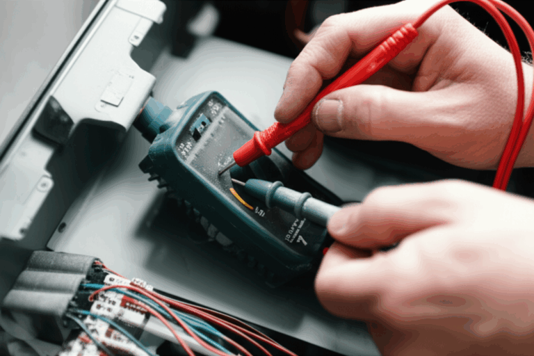
- Inspect insulation resistance with a megohmmeter if the motor sat in storage or got wet.
- Check alignment and coupling. Soft foot can twist the frame which loads bearings.
- Tighten terminations and lug connections. Loose lugs cause heat and nuisance trips.
- Confirm enclosure type suits the environment. TEFC for dusty areas. Washdown for food plants. Explosion proof for hazardous locations.
- Set overload protection in the starter or VFD based on full load amps and service conditions.
- Verify grounding and bonding. A clean ground saves headaches with VFDs and EMC.
- Check cooling flow. Nothing kills a motor faster than heat buildup.
Maintenance, troubleshooting, and predictive checks
Good motors don’t ask for much. Give them a little and they give you years.
Routine care
- Keep them clean. Dust blankets trap heat.
- Grease bearings per manufacturer guidance. More grease is not always better.
- Tighten electrical connections during shutdowns.
- Inspect vibration and noise. Listen with your ear and a simple vibration meter.
- Log temperatures and currents. Trends tell you what’s changing.
Predictive tools I trust
- Vibration analysis: Finds bearing wear, imbalance, misalignment, and looseness early.
- Infrared thermography: Hot spots on terminals or bearings stand out.
- Insulation testing: Periodic megger tests catch moisture and insulation degradation.
- Current signature analysis: Can hint at broken rotor bars or eccentricity.
Troubleshooting tips I use
- Motor hums but won’t turn: Check phase loss, overload trips, or jammed load.
- Trips on start: Look for mechanical binding, wrong starter setting, or undersized supply.
- Overheating: Verify voltage, unbalance, ventilation, and overloading. Check VFD parameters if installed.
- Vibration and noise: Check alignment, bearings, rotor balance, and base rigidity.
- Low torque: Confirm connection links, delta vs star mistakes, and weak phase.
Applications you’ll see in the real world
I’ve worked across a lot of industries. Three phase motors show up everywhere.
- Manufacturing plants: Conveyors, machine tools, mixers, extruders, and textile machinery.
- Pumps and fans: Water and wastewater treatment, HVAC systems, blowers, and cooling towers.
- Compressors: Air compressors and refrigeration compressors.
- Material handling: Elevators, cranes, hoists, and conveyor belts.
- Agriculture: Irrigation pumps, grain dryers, feeders, and augers.
- Mining and cement: Crushers, mills, and heavy duty fans.
- Food processing and washdown: Hygienic enclosures with sealing against jets and chemicals.
- Commercial buildings: Chillers, big air handlers, and escalators.
- Electric vehicles: Traction motors run three phase AC using inverters. While EVs use specialized motor types the 3 phase principles still apply.
Selecting the right 3 phase motor for your job
When someone asks me to “pick a motor” I slow the conversation down. I ask a dozen questions. The right motor depends on more than horsepower.
- Load profile: Constant torque like conveyors or variable torque like pumps and fans. Variable torque loads pair beautifully with VFDs because affinity laws reward speed reduction with huge energy savings.
- Speed and control: Fixed speed with across-the-line starting or variable speed with a VFD. Do you need dynamic braking or regenerative braking.
- Starting torque: High inertia loads may need soft start or a larger motor. Wound rotor motors can shine in special cases.
- Duty cycle: Continuous duty or intermittent. Start-stop frequency matters for heating.
- Environment: Dust, moisture, washdown, altitude, and ambient temperature. Pick the right enclosure and insulation class.
- Standards and sizes: NEMA vs IEC frames. Local codes and utility rules. NEMA Design B is common for general purpose. Hazardous location ratings if required.
- Power source: Voltage and frequency available at the site. Three phase at the right voltage avoids converters. If you only have single phase you might use a VFD that accepts single phase input and outputs 3 phase for smaller motors. Some use static or rotary phase converters but I prefer VFDs for control and protection.
- Mechanical interface: Mounting, shaft size, and coupling. Don’t forget the base and guard.
- Budget and total cost: High efficiency motors can pay back with lower energy use.
Costs, lifespan, and total cost of ownership
Price tags can mislead. I’ve seen teams buy the cheapest motor then spend far more on energy and downtime over the years.
- Upfront vs energy: IE3 or IE4 motors cost more. They run cooler and use less energy. Over thousands of hours those savings add up.
- Maintenance: Simpler designs like squirrel cage induction motors keep maintenance costs down. Good bearings and seals pay for themselves.
- Environment: Dusty, hot, or wet locations shorten life. Pick the right enclosure and you avoid early failures.
- Quality of materials: High grade laminations reduce core losses. You don’t see that from the outside. The manufacturing details matter. If you want a sense of what goes into that choice, check how suppliers engineer motor core laminations.
Frequently asked questions I hear all the time
What is a 3 phase motor in one sentence
It’s an AC motor that uses three phase power to create a rotating magnetic field in the stator which drives the rotor with smooth torque and high efficiency.
How does motor speed relate to frequency and poles
Use the synchronous speed formula Ns = 120 × frequency ÷ poles. Actual induction motor speed will be a bit lower due to slip.
Why is three phase “better”
Three phase gives smoother power, self starting torque, and higher efficiency. It also integrates easily with VFDs for speed control.
Can I run a 3 phase motor on single phase power
Yes for smaller motors in some cases. A VFD with single phase input and 3 phase output can run the motor at reduced power. Rotary phase converters work too but they add losses and complexity. For large motors I prefer a proper three phase supply.
What’s the difference between delta and wye connections
They change the voltage across each winding and can affect starting current and torque. Dual voltage motors often use wye for higher voltage and delta for lower voltage. Always follow the nameplate and the wiring diagram.
What is power factor and should I care
Power factor is the ratio of real power to apparent power. Low power factor means extra current flows that does no work. Utilities may charge penalties for it. You can correct power factor with capacitors or synchronous machines.
How do VFDs save energy
On variable torque loads like fans and pumps the power scales roughly with the cube of the speed. Slow the fan a bit and power use drops a lot. VFDs let you match speed to demand which slashes energy costs.
What protection should I use
Use proper overload relays, short circuit protection, and motor starters or VFD protections. Thermal sensors embedded in windings help on critical motors. Make sure the contactor and circuit breaker match the motor’s current and duty.
What causes motor vibrations
Imbalance, misalignment, loose foundations, bearing issues, rotor problems, and electrical unbalance. Fix the root cause. Don’t just turn up the volume on the radio to drown out the noise.
What materials affect motor efficiency
The stator and rotor laminations and the winding quality drive losses. High grade silicon steel and precise lamination stacks reduce eddy currents and hysteresis losses. If you’re curious about the materials and processes behind those stacks, take a look at stator core lamination and electrical steel laminations.
A few real-world lessons I learned the hard way
- Check phase sequence before coupling: I once had a pump running backward on first start. It happens. Bump test uncoupled then swap two leads if rotation is wrong.
- Don’t ignore airflow: A clogged guard or blocked fan shroud can roast a motor. I’ve seen a perfectly healthy motor cook itself in a week because someone stacked boxes around it.
- Star-delta wiring matters: Misplaced links in the terminal box caused low torque and a lot of head scratching. Triple check before energizing.
- VFD grounding and cable choices: Long cable runs and poor bonding caused nuisance trips and bearing currents. Use proper VFD-rated cable, keep cables short if possible, and bond everything well.
- Listen to the bearings: A bearing that sings today will scream tomorrow. Vibration and temperature trends tell the story early.
Deep dive: Induction motor torque and slip in simple terms
Torque in an induction motor depends on the slip. Slip is the difference between synchronous speed and actual rotor speed. At standstill the slip is 1. As the motor speeds up the slip drops. Maximum torque happens at a certain slip. Designers shape the rotor bar geometry to get the right starting torque and running behavior. Squirrel cage rotors with deep bar designs can boost starting torque. Wound rotor motors let you add external resistance to tune torque at low speed.
Speed control and braking
- With a VFD you can control speed across a wide range. You maintain good torque at low speeds using vector control or field oriented control.
- Braking options include DC injection braking and dynamic braking with a resistor bank. Regenerative drives can feed energy back to the line if the system supports it. I’ve used regen on hoists and test stands where the load drives the motor.
Protection and control circuits
- Overload relays protect against sustained overcurrent that causes heating. Set them based on full load amps and ambient conditions.
- Contactors and relays implement start-stop control. Interlocks prevent unsafe combinations like forward and reverse at the same time.
- PLC motor control allows sequencing and safeties. You can add permissives like low oil pressure or closed valve confirmation to protect pumps.
- Sensors like PTC thermistors embedded in the windings offer extra protection through the VFD or a relay module.
Noise, vibration, and motor enclosures
- Noise levels depend on bearings, cooling fans, and magnetic forces. VFDs can cause audible whine at low switching frequencies. Raise the switching frequency within drive limits to reduce it or use a sine filter for long runs.
- Enclosure choice affects noise and cooling. TEFC motors use an external fan on the shaft. ODP motors run cooler in clean spaces. Washdown motors get smooth housings and better seals for food and beverage plants. Explosion proof motors contain sparks and hot gases in hazardous locations.
Standards and classifications you’ll see
- NEMA and IEC set frame sizes, mounting, and performance classes.
- Insulation classes define permissible temperature rise.
- IP ratings define protection against dust and water.
- Energy efficiency classes IE1 through IE4 define minimum performance levels.
- Service factor clarifies overload capability under specified conditions.
Connections to the power system
- Three phase power comes from the grid, generators, or inverters. Plants might use transformers to step voltage up or down. Laminated cores in both motors and transformers reduce losses. That’s why the quality of the steel and the lamination work matters just as much in motors as it does in transformers.
- Balanced loads keep transformer heating under control. Unbalanced loads and harmonics shorten transformer and cable life.
When single phase is all you have
I’ve had projects in rural locations with only single phase utility power. For small to medium motors I’ve had good results using a VFD that accepts single phase input and outputs three phase. You derate the drive but you get soft start, overload protection, and speed control in one package. Static phase converters can start a motor yet they usually leave you with lower running performance. Rotary phase converters produce a third leg using a spinning idler motor. They work, although they add complexity and loss. When it’s a critical process I push for true three phase from the utility or a generator.
Environmental impact and energy use
Every kilowatt saved in your process reduces upstream generation needs. Three phase motors with high efficiency designs and VFD control can cut energy use in HVAC systems and pumping applications. It’s not just a bill issue. It’s a footprint issue. If you multiply the savings across every fan and pump in a facility the numbers get serious.
A quick word on materials and core losses
Core losses come from eddy currents and hysteresis inside the steel. That’s why motor cores use thin insulated laminations rather than solid steel. Better grades of silicon steel reduce losses and heat. Precision in stacking and punching matters. If you want to see what goes into these cores at a manufacturing level the overviews on motor core laminations, stator core lamination, and electrical steel laminations lay out the fundamentals.
Putting it all together: A simple selection and setup example
Let’s say you need to drive a 30 kW pump in a water treatment plant.
- Load: Variable torque with a wide flow range.
- Power: 400 V three phase at 50 Hz available.
- Choice: High efficiency IE3 squirrel cage induction motor. TEFC enclosure. Class F insulation with Class B rise gives thermal headroom.
- Control: VFD for speed control. You save energy by matching pump speed to demand. You add soft ramp to avoid water hammer.
- Protection: Thermal sensors in the windings wired to the VFD. Proper overload settings based on nameplate full load amps.
- Power quality: Line reactor on the VFD input. Output dV/dt filter if cable runs are long.
- Wiring: Wye connection for 400 V if the nameplate calls for it. Confirm rotation by bumping uncoupled then couple and align.
- Maintenance: Quarterly bearing checks and visual inspections. Annual IR scan and megger test if the motor is critical.
You end up with a quiet system that sips power at low flow yet can ramp to full speed when needed. You avoid slamming valves and fittings. You extend pump seal life. You make operators happy because it just works.
Final takeaways you can act on today
- Define your load and control needs first. The right motor follows naturally.
- Check your power system. Voltage, frequency, and phase availability decide your wiring and starter choices.
- Use a VFD on variable torque loads. It pays for itself.
- Don’t skimp on materials and build quality. Laminations, bearings, and sealing matter more than brochure gloss.
- Keep it clean, cool, and aligned. Motors last when you respect heat and mechanics.
Conclusion: The unsung workhorse of modern industry
If you walk through any factory, plant, or high rise you’ll hear 3 phase motors doing quiet work. They turn electricity into motion with grace. They start without drama. They run for years when you treat them right. I’ve leaned on them in harsh mines, spotless food plants, and everything in between. Learn how they work. Pick them well. Wire them right. Protect them with smart controls. They will pay you back in uptime and lower energy bills.
That’s what a 3 phase motor is. It’s the backbone of modern mechanical systems. It’s simple in concept and powerful in practice. Once you see the rotating magnetic field in your mind, everything else clicks. And once you hear that steady hum, you’ll know your process is in good hands.