What Energy Transformation Occurs in an Electric Motor? The Lamination Engineer’s Guide to Turning Electrons into Motion
Every design engineer faces the same core question sooner or later. How does an electric motor actually convert electrical energy into mechanical energy, and what does lamination design have to do with that transformation? If you’re choosing a stator stack material for a new BLDC design, debating lamination thickness for a high-speed induction motor, or validating a supplier’s manufacturing process, you’re in the right place. Getting this right improves motor efficiency, lowers operating temperature, trims energy consumption, and extends service life. It also saves real money over the product’s lifetime.
This guide uses a simple framework: Problem, Explain, Guide, Empower. We’ll start with what you need to solve, explain the physics in plain language, lay out your options with honest trade-offs, then give you clear next steps you can act on. We’ll also connect the dots between physics and procurement decisions, because engineering teams and sourcing teams succeed together when the energy transformation story is clear end to end.
In This Article
- Why Lamination Material Choice Is Critical to Energy Transformation
- The Core Energy Transformation: Electrical to Mechanical
- What’s Really Going On: Core Losses, Heat, Sound, and Vibration
- Your Options Explained: Materials vs. Manufacturing and Assembly
- Which Application Is This For: Matching Solutions to Use Cases
- Motor Efficiency and the Energy Balance Equation
- Different Motor Types and Their Energy Pathways
- Practical Implications: Energy, Cost, and Sustainability
- FAQs
- Your Engineering Takeaway
Why Lamination Material Choice Is Critical to Energy Transformation
Let’s frame the problem. You need a motor that takes electrical input and delivers mechanical output with predictable torque, speed, and power. You want to minimize wasted energy from eddy currents, hysteresis, friction, and windage. You also have constraints. Cost targets, supply chain risk, tooling lead times, efficiency mandates like NEMA Premium or IE3/IE4, and the realities of production.
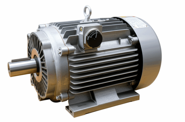
The motor’s magnetic core sits right at the center of this energy transformation. It routes magnetic flux efficiently, it resists unnecessary heating, and it supports your torque per amp goals. The core’s laminations, their thickness, their insulation coatings, and how they’re cut and stacked all decide how much of your electrical energy becomes mechanical energy versus heat and sound. That is why lamination choice carries real weight in your performance budget.
If you need a quick mental picture, think of energy flow in a motor like money through a business. You want as much of the revenue to reach productive work as possible. Taxes and fees still exist. In motors those “fees” are Joule heating in copper, eddy current and hysteresis losses in the steel, friction, windage, and a bit of sound and vibration. Smart lamination choices cut those fees down.
The Core Energy Transformation: Electrical to Mechanical
At its heart, a motor converts electrical energy to mechanical energy. We feed current and voltage to the windings, and the motor outputs torque and speed. That gives mechanical power. The physics follows a straight line.
- Input: Electrical energy. In DC systems think voltage and current. In AC systems add power factor and frequency to the picture.
- Process: Electromagnetism. Current in a conductor creates a magnetic field. Magnetic fields interact with each other. The resulting Lorentz force produces torque on the rotor.
- Output: Rotational mechanical energy. Torque times angular speed equals mechanical power.
In compact terms:
- Electrical input power ≈ V × I for DC and V × I × power factor for AC
- Mechanical output power = torque (Nm) × angular speed (rad/s)
- Efficiency (%) = output mechanical power / input electrical power × 100
Engineers often sketch a motor energy diagram or energy flow chart to visualize this. Electrical input flows into the stator windings, interacts with the rotor’s magnetic field, and results in torque on the shaft. Some energy takes a detour and becomes heat in the copper, heat in the steel, aerodynamic drag, and audible sound.
The Fundamental Principle: Electromagnetism
- Magnetic field from current: A current through a coil produces magnetic flux. The stator or rotor laminations provide a low reluctance path for that flux. Think permeability like a sponge for magnetic field lines. A high-permeability material “soaks up” magnetic flux easily.
- Interaction of magnetic fields: The stator field and rotor field try to align. That mismatch creates force. The same physics that makes a compass needle move drives your rotor to spin.
- Lorentz force and torque: Charge carriers in a conductor moving through a magnetic field experience a force. In a motor, geometry turns that force into torque. Torque then accelerates the rotor and delivers mechanical work to the load.
Whether it’s a DC motor with commutator and brushes, a BLDC motor with electronic commutation, or an AC induction motor where a rotating stator field induces rotor currents by Faraday’s law, the core story stays the same. Electrical energy becomes rotational kinetic energy.
What’s Really Going On: Core Losses, Heat, Sound, and Vibration
No energy conversion hits 100% efficiency. Energy conservation still holds. The difference between input electrical energy and output mechanical energy leaves as heat, sound, and vibration. Understanding where those losses come from lets you target them.
Think of eddy currents like tiny whirlpools in a river. A changing magnetic field induces circulating currents in any conductive mass by Faraday’s law. Those currents waste energy as Joule heating.
- Eddy current losses: Proportional to the square of lamination thickness and roughly to the square of frequency. Thinner laminations and good interlaminar insulation break up those whirlpools. You get less heat and more useful torque per amp.
- Hysteresis losses: Every AC or PWM cycle drives the steel around a loop on its B-H curve. The loop area equals energy lost per cycle. Materials with lower coercivity have narrower loops. You lose less energy to hysteresis. That is why steel grade matters.
- Copper (I²R) losses: Resistance in windings turns current into heat. Better slot fill, lower resistance wire, and proper conductor sizing reduce these losses.
- Mechanical losses: Friction in bearings and brushes, windage losses from air drag on the rotor. At higher speed windage grows quickly and can create heat and a bit of sound energy.
- Stray load losses: Leakage flux, slot harmonics, and other parasitic effects that increase with load. Harder to measure. Still real.
Why do motors get hot? Because the conversion isn’t perfect. Joule heating in copper and steel dominates, then friction and windage bring their share. Sound and vibration losses exist but usually stay small in the total energy balance.
If you plot an energy balance for a motor at steady load, it looks like this:
- Input electrical energy = output mechanical energy + copper heat + core heat (eddy + hysteresis) + mechanical losses (friction + windage) + sound and vibration
Industrial motors can run 90 to 96% efficient at rated load with NEMA Premium or IE3/IE4 levels. Large high-quality machines can approach 97 to 98% under ideal conditions. Small motors below 1 horsepower vary widely and can drop to 50 to 85% depending on design and duty.
Your Options Explained: Materials vs. Manufacturing and Assembly
This is where design meets procurement. The choices you make on material, thickness, insulation coating, and manufacturing route will either unlock or hinder your energy transformation goals.
Material Considerations: Electrical Steel and Beyond
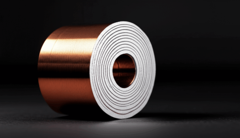
- Non-oriented silicon steel (CRNGO): The workhorse for motor laminations. It delivers balanced magnetic properties in all directions. Common thicknesses include 0.50 mm, 0.35 mm, and 0.27 mm. Thinner gauges reduce eddy current loss especially at higher frequency or high PWM ripple. Lower core loss grades cost more per kilogram yet can drop your system’s kWh consumption meaningfully over life.
- Grain-oriented silicon steel (CRGO): Optimized for one direction. Excellent for transformers with unidirectional flux. Not common for rotating machines because motor flux rotates. Use CRGO for transformer lamination core designs, not for induction or BLDC motor cores.
- High-silicon or cobalt alloys: In high-power-density designs where mechanical stress and temperature run high, cobalt-based alloys deliver higher saturation flux density. That lets you push torque without saturating. They cost more. Use them when the power density and thermal headroom justify the spend.
- Soft magnetic composites and amorphous metals: Niche use in motors. Useful in 3D flux paths or very high-frequency applications. Manufacturing and cost can be limiting.
- Insulation coatings: These are thin organic or inorganic films applied to each lamination surface. They raise interlaminar resistance. Eddy currents shrink. The coating class also affects punchability, bondability, and thermal rating.
If you need a primer on materials and their use across motors and transformers you can review foundational information about electrical steel laminations.
Key properties to watch:
- Magnetic permeability: How easily the material allows magnetic field lines to pass. Higher permeability reduces magnetizing current and improves torque per amp.
- Saturation flux density: Higher saturation lets you carry more flux in the same cross section. That increases peak torque before saturation softens the B-H slope.
- Coercivity: Resistance to demagnetization. Lower coercivity reduces hysteresis loss.
- Resistivity: Higher resistivity reduces eddy current loss at a given thickness.
- Loss curves vs frequency and flux density: Look at manufacturer data for total core loss (W/kg) across operating points that match your motor’s waveform and speed.
Manufacturing and Assembly Processes: How You Make It Matters
- Stamping with progressive dies: Best for high volume. Consistent burr control. Good edge quality. Lowest cost per part at scale after tooling amortization. Requires upfront tooling time and budget. Burrs and work hardening increase local losses if uncontrolled. Proper annealing can restore magnetic properties.
- Laser cutting: Excellent for prototyping, low-volume production, and intricate geometries. No hard tooling. Heat-affected zones can degrade magnetic properties near edges if parameters are not tuned and if no post-anneal is done. Ideal for fast iteration and complex BLDC stator teeth or skewed rotor slots in short runs.
- Wire EDM: Precise edges and tight tolerances. Slower and costlier. Often used for sample stacks and specialized parts where edge quality dominates.
- Waterjet: Avoids thermal effects but can leave surface roughness that affects stacking factor and insulation. Rare in production laminations.
- Stacking methods: Interlocking tabs (think LEGO bricks) create rigid stacks without welding. Bonded stacks use adhesives or specialized coatings that cure during lamination bake. Mechanical fasteners and rivets add structure but can create local magnetic discontinuities. Welding can degrade magnetic properties in the heat affected zone unless controlled with post-anneal or minimal weld strategy.
- Annealing: Critical after stamping or cutting to reduce residual stresses and restore low-loss magnetic behavior. Follow material supplier guidance on time and temperature. Verify by core loss testing on coupon samples.
- Skewing: Skewed rotor or stator slots reduce cogging torque and acoustic noise. They also slightly increase flux path length and can add a small efficiency penalty. It is a trade you can quantify.
- Stack height, stacking factor, and fill: Stacking factor measures how much steel you actually have versus insulation and air in the stack. Higher factor increases effective flux path and torque density. Insulation coatings and bonding methods affect this.
These manufacturing choices change the motor energy transformation in subtle ways. Better edge quality and controlled burrs reduce stray losses and local heating. Reliable interlaminar insulation lowers circulating current paths. Good stacking raises effective permeability and improves energy flow in the motor from electrical to mechanical output.
If you want to see how these choices show up in product families you can scan an overview of motor core laminations.
Which Application Is This For: Matching Solutions to Use Cases
Choosing the “best” path depends on the motor type, duty cycle, speed, and the business case. Here’s a practical map.
- EV traction motors and high-speed compressors: You fight high frequency, high PWM ripple, and significant thermal loads. Use thin-gauge non-oriented silicon steel with low core loss. Consider skewing and precision balancing to reduce vibration energy and sound. Stamping for volume or laser for early validation. Bonded stator stacks help damp vibration and improve thermal conduction to the housing.
- Industrial induction motors for pumps and fans: Efficiency targets often follow NEMA Premium or IE3/IE4. Progressive die stamping makes sense at volume. Focus on low-loss CRNGO grades at the right thickness. Invest in robust insulation coatings and consistent anneal. Keep friction losses low with bearing selection and proper alignment. Manage windage with tight air gaps and smooth rotor surfaces.
- Robotics and servomotors: High dynamic response and high torque per volume. BLDC or permanent magnet synchronous machines shine here. Thin laminations reduce eddy current losses at high electrical frequencies. Precision laser cutting can help with complex slot geometries in early stages. Move to stamping once the design locks. Confirm rotor lamination stack concentricity to keep vibration energy low during rapid acceleration.
- Home appliances and smaller motors: Cost matters more. You may accept a thicker lamination with slightly higher core loss. Look for smart trade-offs in winding design to control copper losses and heat. Focus on robust manufacturing to keep consistency high over large quantities.
- Aerospace and medical: When weight and performance rule, cobalt alloys and ultra-thin laminations may be justified. Validate with detailed core loss testing under the exact waveform you expect.
Be honest about limitations. Laser cutting gives stellar flexibility for prototypes and small runs. It may not meet your cost target for high-volume production of simple geometries. Interlocking laminations build strong stacks without welding heat effects. They require careful tab design to protect stacking factor and avoid local stress.
If you need to orient your design thinking around stator geometry and its direct impact on flux paths and torque ripple you can explore the role of the stator core lamination. For rotor topologies and their influence on torque production and windage at speed you can review the fundamentals of rotor core lamination.
Motor Efficiency and the Energy Balance Equation
Let’s quantify the transformation. Engineers and procurement teams need numbers to align on value.
- Energy balance: Input electrical energy = output mechanical energy + lost heat energy + sound and vibration. Express it as power when you look at steady operation.
- Mechanical output: Pout = torque × speed. Use Nm for torque and rad/s for angular speed. Convert speed in rpm to rad/s by multiplying by 2π/60.
- Electrical input: For DC, Pin = V × I. For AC, Pin ≈ √3 × Vline × Iline × power factor for three-phase systems. Drive waveforms with high harmonic content change effective core losses, so use realistic test conditions.
- Efficiency: η = Pout ÷ Pin × 100. Small motors may land between 50 and 85%. Industrial machines often reach 90 to 96%. Large units can approach 97 to 98% in optimized conditions.
Breakdown of losses in a typical industrial AC induction motor at rated load can look like this:
- Copper losses: 30 to 40% of total losses
- Core losses: 20 to 30%
- Mechanical losses: 10 to 20%
- Stray load losses: 15 to 25%
Those ranges reflect general industry guidance under standards such as IEEE 112 and IEC 60034-2-1. Actual numbers depend on design, load, speed, and waveform.
Why thickness matters: Eddy current loss scales roughly with the square of lamination thickness. Halve thickness and you can cut eddy losses by up to 75% at the same frequency and flux density. Hysteresis loss depends on material chemistry and processing. Better grades with lower coercivity tighten the B-H loop and reduce loss per cycle.
Heat matters in your energy balance because it sets winding temperature and insulation life. Lower core loss drops steady-state temperature rise. That improves bearing grease life, winding insulation life, and magnet longevity in PM designs. In short, better laminations protect your motor’s lifespan.
Different Motor Types and Their Energy Pathways
Different topologies move energy in slightly different ways, yet the same principles apply.
- DC motors: A DC supply and a commutator with brushes switch current in the armature windings. The interaction between the armature field and stator field produces torque. You get steady torque at low speed and simple control. Energy loss includes brush friction, commutator heating, copper and core losses. Brush wear also matters for maintenance.
- AC induction motors: The stator’s alternating current creates a rotating magnetic field. Faraday’s law induces current in the rotor bars. The rotor current interacts with the stator field by Lorentz force and produces torque. Rotor slip ensures induction. This type dominates industry due to ruggedness and cost effectiveness.
- BLDC and permanent magnet synchronous motors: Permanent magnets on the rotor create a constant field. The stator windings get commutated electronically to create a rotating field that pulls the rotor along. High torque density and high efficiency make them ideal for robotics, electric vehicles, and appliances.
In all three, your lamination design influences magnetic flux paths, core losses, and thermal performance. The more effectively your core routes magnetic energy without wasting it, the more of your electrical input becomes useful mechanical output. You can go deeper on BLDC stator geometry and slot structures in resources that focus on the bldc stator core.
Practical Implications: Energy, Cost, and Sustainability
Motors consume a staggering share of global electricity. Industry sources estimate that electric motors use nearly 50% of the world’s electricity and about 70% of industrial electricity. That scale means small improvements in motor energy efficiency amplify into large energy savings.
Consider a simple upgrade case. Swap a standard 75% efficient motor for a 90% efficient one in a 20 HP application that runs 6,000 hours per year at 75% load. The annual energy savings can reach roughly 12,000 kWh depending on utility factors. At $0.10 per kWh that is about $1,200 per year saved. Over a multi-year service life you pay back any premium for better material and smarter manufacturing quickly.
Sustainability gains follow. Lower losses mean lower CO2 emissions upstream. Waste heat gets cut. In some industrial settings, you can even capture waste heat from large motors to preheat fluids or warm spaces. That changes plant-level energy balance and boosts system efficiency.
From a procurement perspective, the trade-off between per-unit price and lifetime energy cost often supports a better lamination grade. Factor in maintenance windows and downtime risk. Cooler running motors last longer. Bearings like cooler housings. Permanent magnets like stable temperatures. That stability reduces unexpected failures and protects your schedule and OEE metrics.
FAQs
Q: What is the primary energy transformation in a motor?
A: Electrical energy converts into mechanical energy. Current and voltage feed the windings. Magnetic fields interact. Lorentz force generates torque. The rotor spins. That is your mechanical output.
Q: Why do electric motors get hot?
A: Losses. Copper I²R heating in windings. Core losses from eddy currents and hysteresis in the steel. Mechanical friction in bearings and brushes. Windage from air drag. A small part leaves as sound and vibration energy.
Q: Can a motor achieve 100% energy efficiency?
A: No. Energy conversion always carries some loss. You can push efficiency very high with optimized laminations, premium windings, and high-quality bearings. You still have residual losses.
Q: How does a motor’s energy transformation compare to a generator’s?
A: A motor converts electrical to mechanical energy. A generator does the opposite. Mechanical input spins the machine. Faraday’s law induces voltage and current in the windings. The same machine can act as either with appropriate design and control.
Q: What causes motor heat during variable frequency drive operation?
A: Higher electrical frequency and harmonic content can increase core losses. That means more eddy currents and hysteresis per unit time. Proper lamination thickness and steel grade choices keep that extra heat in check.
Q: Which losses dominate at high speed?
A: Windage increases with speed. Core losses rise with frequency. Both can dominate beyond a threshold. Good aerodynamics, smooth rotor surfaces, and thinner laminations help.
Q: Which metrics should I request from a lamination supplier?
A: Material grade and thickness, core loss curves at your expected flux densities and frequencies, stacking factor, insulation coating class, burr height after cutting, anneal process and certification, and sample test data for loss after processing.
Your Engineering Takeaway
Here are the key points you can bring to your next design review or supplier call:
- The core transformation: Electrical energy becomes mechanical energy by electromagnetism. You measure success in torque, speed, and efficiency.
- Core losses matter: Eddy currents and hysteresis in the laminations convert useful energy into heat. Thinner, well-insulated laminations and low-loss steel grades reduce those losses.
- Manufacturing drives performance: Stamping for volume, laser or EDM for prototypes or complex small runs. Control burrs, apply proper anneal, and pick stacking methods that protect magnetic properties.
- Match the solution to the application: EV traction and high-speed designs benefit from thinner gauges and low-loss grades. Industrial motors focus on NEMA Premium or IE3/IE4 targets with robust processes for consistency.
- Efficiency pays back: Lower losses reduce operating temperature, extend life, and save kWh. The business case often favors higher quality laminations over the motor’s lifetime.
If you want a quick refresher on part families to facilitate internal alignment across engineering and sourcing you can explore an overview of core lamination stacks.
Looking for specific guidance on lamination thickness, insulation class, or manufacturing routes for your next program? Bring your target speed, torque, duty cycle, and space claim. Add your cost and efficiency goals. With that, you can have a productive conversation with a lamination supplier and lock in a path that turns more of your electrical input into motion with less waste heat and less sound.
Appendix: A Plain-Language Mini Glossary
- Electrical energy: What you supply to the motor as voltage and current. Measured in watts or kilowatt-hours over time.
- Mechanical energy: What you get on the shaft as torque and speed. Power equals torque times angular speed.
- Electromagnetism: The physics that links current, magnetic fields, and force. Faraday’s law governs induction. Lorentz force produces torque.
- Magnetic field and flux: The “flow” of magnetic influence through the core. Materials with high permeability route this flow efficiently.
- Eddy current losses: Circulating currents induced in steel by changing magnetic fields. They create heat. Thinner laminations and good insulation block them.
- Hysteresis loss: Energy lost every time the steel cycles around the B-H curve. Lower coercivity means lower loss per cycle.
- Friction and windage: Mechanical losses from bearings and air drag. They increase heat and reduce efficiency at speed.
- Efficiency: The fraction of input energy that becomes useful mechanical output. You express it as a percentage.
- Power rating: The rated mechanical output a motor can deliver continuously without exceeding temperature rise limits.
- Torque: The twisting force on the shaft. Measured in newton-meters (Nm).
Bringing It Back to Decisions You Need to Make
You do not have to choose between clarity and performance. Start with the physics in simple terms. Quantify your energy balance. Choose lamination material and thickness that match your electrical frequency and torque density targets. Select manufacturing and stacking methods that protect magnetic properties and scale to your volume. Then validate with realistic test waveforms that reflect your inverter and load.
Do that, and you will turn more electrons into motion with less waste. Your motor runs cooler. It lasts longer. It costs less to own. That is the energy transformation story done right.