What Does the Stator Do in ATP Synthase? An Engineer’s Guide to Better Motor Laminations
Every motor designer lives with a simple truth. If the stator does not hold firm and direct energy where it needs to go the whole powertrain loses efficiency. Biology figured this out long ago. ATP synthase, the tiny rotary engine in your cells, uses a stator to anchor the catalytic head while a rotor spins inside. That same principle applies to electric machines on your desk or in your plant. The stator must stand still. The rotor must turn. The laminations must guide magnetic flux cleanly with minimal loss.
If you are choosing a lamination material, debating stamping versus laser cutting, or trying to cut core losses at higher frequencies this guide will help. We will use ATP synthase as the perfect molecular analogy for what your stator has to do. Then we will translate those lessons into practical engineering decisions for stator and rotor laminations that improve torque density, thermal performance, and cost.
In This Article
- Why This Matters to Motor Designers and Procurement
- ATP Synthase 101: The Biological Benchmark for Stators
- Translate Biology to Motors: What Your Stator and Laminations Must Do
- Material Considerations: Choosing the Right Electrical Steels
- Manufacturing and Assembly Processes That Protect Magnetic Performance
- Which Application Is This For? Best Fit by Use Case
- Procurement and Quality Control: Getting What You Specified
- The Indispensable Importance of the Stator for Energy Conversion
- Your Engineering Takeaway
Why This Matters to Motor Designers and Procurement
Here is the practical problem. You need high efficiency and stable torque across your duty cycle without driving material cost through the roof. Stator laminations sit at the heart of that trade space. Thickness, grade, coating, and the way you stack and join laminations all shape eddy current loss, hysteresis loss, and noise. Procure the wrong steel or pick the wrong process and you lock in heat and inefficiency.
If you want a mental model that sticks think about ATP synthase. It is the most efficient rotary energy converter known. It uses a rotor and a stator. The stator anchors the catalytic head so the central shaft can convert a proton motive force into ATP. Your job is similar. Anchor the magnetic circuit. Guide flux. Prevent unwanted motion. Convert electrical energy to mechanical work with minimal loss.
We will first explain what the stator does in ATP synthase because the physics lesson is clean and intuitive. Then we will show you how to pick materials and processes for stator and rotor cores that honor the same engineering principles.
ATP Synthase 101: The Biological Benchmark for Stators
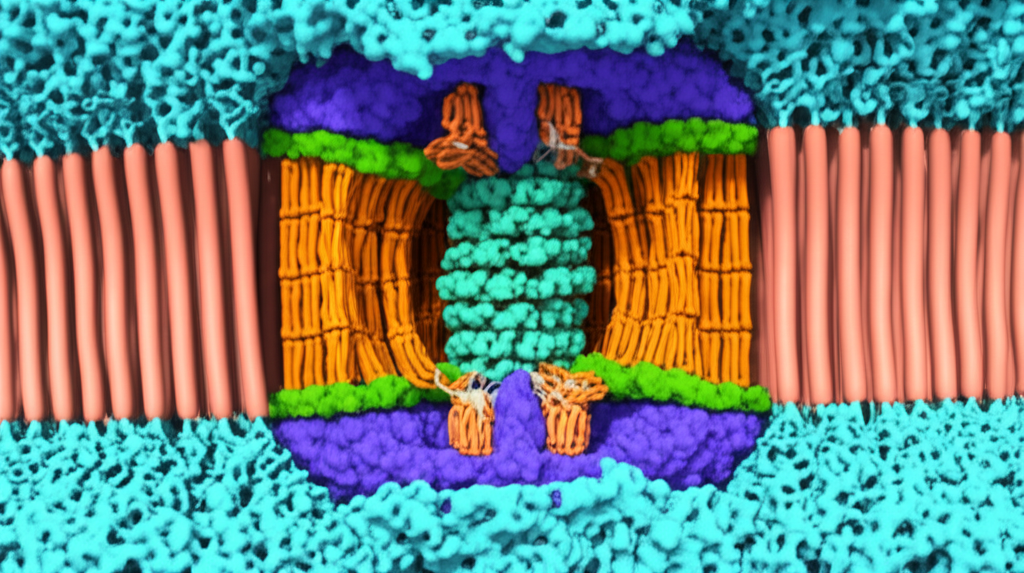
ATP synthase is a two-part machine. Biologists label the membrane-embedded part F0 and the soluble catalytic part F1. Together they form the F0F1 ATP synthase complex found in mitochondria, chloroplasts, and many bacteria. It sits in the inner mitochondrial membrane or thylakoid membrane and taps an electrochemical proton gradient known as the proton motive force. That gradient arises from oxidative phosphorylation in respiration or from photosynthetic electron transport in chloroplasts. Peter Mitchell’s chemiosmotic theory predicted this energy transduction and won the Nobel Prize in 1978.
Engineers can map this to a motor easily:
- The F0 domain is the “stator side” of the membrane that houses a stationary proton channel in subunit a and a rotating c-ring. It forms the proton-conducting sector.
- The F1 domain is the catalytic head that makes ATP. It is the stationary frame where work happens.
- The rotor comprises the c-ring and the central stalk formed by the gamma and epsilon subunits.
- The stator comprises the subunit a proton channel and the peripheral stalk formed by subunits b and delta. This stalk connects F0 to the F1 alpha3beta3 hexamer and holds it fixed.
Defining the Stator in ATP Synthase
The stator is the fixed anchor in a spinning machine. It spans from the membrane F0 sector to the F1 head. Its composition depends on the organism yet the functions rhyme:
- Subunit a forms half-channels that let protons enter from one side of the membrane and exit on the other. It interfaces tightly with the c-ring and does not rotate.
- The peripheral stalk is a rigid arm built from a b dimer and associated subunits such as delta, OSCP, F6, and d in the mitochondrial enzyme. This stalk locks the F1 alpha3beta3 catalytic ring in place.
Cryo-electron microscopy and X-ray crystallography have resolved this architecture in great detail. John Walker worked out much of the structural arrangement. Paul Boyer proposed the binding change mechanism for catalysis. They shared the 1997 Nobel Prize in Chemistry for those insights. The architecture supports rotational catalysis where the central stalk turns inside a stationary catalytic head.
The Stator’s Pivotal Role: Preventing Co-Rotation and Directing Energy
The stator solves a simple problem. Proton flow through F0 generates torque on the c-ring. That torque travels into the gamma subunit. If nothing holds the F1 head still the whole enzyme would spin like a merry-go-round. No relative motion would occur between the central stalk and the catalytic sites. No ATP would form.
The stator prevents co-rotation. It fixes the alpha3beta3 ring. It provides the non-rotating reference that converts proton current into mechanical rotation inside the catalytic head. That fixed reference allows the rotor to force sequential conformational changes at the beta catalytic sites. Those sites cycle through Open, Loose, and Tight states to bind ADP and inorganic phosphate, form ATP, and release it. This coupling is the essence of the energy conversion.
How Rotational Catalysis Works
You can walk through the mechanism in four steps:
1) Proton gradient: Protons descend the electrochemical gradient through subunit a. Each proton accesses one of two half-channels that do not span the membrane completely. One half-channel faces the high proton side. The other faces the low proton side.
2) C-ring rotation: A proton binds to an acidic residue such as an aspartate or glutamate on a c subunit in the c-ring. That neutralizes the residue and lets the c-ring rotate within the hydrophobic membrane. When the proton reaches the low side it leaves through the second half-channel.
3) Gamma stalk rotation: The c-ring mechanically couples to the gamma subunit. As c subunits cycle through binding and release the gamma subunit steps around inside the F1 head. Single-molecule experiments by Kinosita and Yoshida showed stepwise rotation up to roughly 130 revolutions per second under favorable conditions.
4) F1 catalysis with a fixed stator: Because the peripheral stalk and subunit a hold the F1 head stationary the asymmetric gamma subunit forces each beta catalytic site through conformational changes. Three ATP form per full 360 degree turn. Under ideal conditions ATP synthase conserves about 90 to 100 percent of the proton motive force energy.
If the stator fails this coupling breaks. Mutations in stator components cause mitochondrial ATP synthase deficiency and severe metabolic disease. Inhibitors like oligomycin block the F0 channel and stall the rotor. Uncouplers short circuit the proton gradient and starve the motor. Everything depends on a solid stator and a guided flow path.
You now have the biological blueprint. A fixed stator. A guided energy channel. A rotor that turns because the stator does not.
Translate Biology to Motors: What Your Stator and Laminations Must Do
In an electric machine the stator and its laminations serve a similar set of functions:
- Provide a fixed mechanical reference so the rotor can develop torque without dragging the frame.
- Offer a low reluctance magnetic path that shapes and directs flux into the air gap while minimizing core loss.
- Resist unwanted motion and vibration so the air gap stays uniform and noise stays low.
- Hold coils or conductors in a geometry that supports efficient energy conversion.
The proton motive force in ATP synthase becomes your voltage and current. The c-ring becomes the rotor. The peripheral stalk becomes your stator yoke and teeth. The subunit a half-channels that guide protons become the carefully designed flux paths in your stator core and back iron.
Engineers can learn two simple lessons from this molecular motor:
- Anchoring matters. The stator must stay mechanically stiff and dimensionally stable under load and temperature.
- Guidance matters. The laminations must channel energy with minimal leakage and loss.
Engineering Fundamentals of Stators and Laminations
Two loss mechanisms dominate in laminated steel cores.
- Eddy current loss: Changing magnetic fields induce circulating currents in the steel. Those loops waste energy as heat. You break up those loops by slicing the core into thin sheets separated by insulating coatings. Think of big eddy currents like whirlpools in a river. Thin insulated laminations break a large whirlpool into many small whirls that die out quickly.
- Hysteresis loss: Magnetizing and demagnetizing the steel each cycle costs energy. The B-H loop area sets that cost. Materials with low coercivity switch magnetization easily which reduces loss.
Key parameters to keep an eye on:
- Thickness: Thinner laminations reduce eddy current loss roughly with the square of thickness. Going from 0.50 mm to 0.35 mm makes a real difference at higher electrical frequencies. It often helps BLDC and high-speed machines. Thinner costs more and raises handling demands.
- Electrical resistivity and coating: Higher resistivity steel and robust interlaminar coatings lower eddy currents further. Coatings also support bonding or interlocking techniques.
- Magnetic permeability: Higher permeability means the material guides flux easily like a sponge that soaks up water. You want high permeability in the working induction range of your design.
- Saturation flux density: Higher saturation allows more flux and torque in a given cross-section. Cobalt alloys push this higher at a steep cost which helps aerospace and traction designs that chase power density.
- Mechanical stiffness and dimensional control: Burrs, warpage, and stack shift erode air gap quality. That eats torque and adds noise.
The “stator-rotor interaction” in biological terms maps to your torque production. The stator must present a uniform magnetic field and a close air gap to the rotor so electromagnetic forces can do their job cleanly.
Material Considerations: Choosing the Right Electrical Steels
You have two families of electrical steels and some specialty options.
- Non-oriented silicon steel (CRNGO): Isotropic magnetic properties in the plane. It is the workhorse for rotating machines. You will see grades like M19, M27, and similar designations across suppliers. These grades balance cost, loss, and saturation.
- Grain-oriented silicon steel (CRGO): Strongly anisotropic. It shines in transformer cores where flux runs along the rolling direction. It rarely fits motor stators because flux rotates. It does fit transformers and inductors.
- Cobalt-iron: High saturation and good strength which boosts torque density and limits deflection. Losses can be higher at low frequency and the cost is significant.
- Amorphous and nanocrystalline alloys: Very low core loss at higher frequencies due to high resistivity and lack of crystalline domains. These materials shine in high-frequency transformers and some specialty machines. They can be harder to process for rotor-stator stacks.
If you are comparing catalog data be sure you are comparing apples to apples. Core loss data depends on test method, flux density, frequency, and coating. The IEC 60404 series describes industry-standard measurements such as Epstein frame and single sheet tester procedures. ASTM standards such as ASTM A677 and related specs cover non-oriented electrical steel sheet with typical mechanical and magnetic property ranges.
When you evaluate options consider both physics and practical sourcing.
- Desired operating induction: Aim for a working peak induction with good margin below saturation for robustness.
- Frequency: Higher frequencies push you to thinner laminations and lower-loss grades.
- Temperature rise: Lower core loss at your operating point cuts stator heat and helps reliability.
- Cost and supply: Confirm real-world availability, thickness options, coating classes, and minimum order quantities.
For a deeper overview of common options and their tradeoffs see the guide on electrical steel laminations.
Grain-Oriented vs Non-oriented in Plain Terms
Motors want non-oriented steel because the magnetic field rotates each cycle. Grain-oriented steel resists magnetization off its rolling direction. That mismatch creates needless loss and torque ripple in motors. Save GO for transformers where the flux path stays aligned. If your design includes both a motor and a transformer you can optimize each core with the right family: CRNGO for the motor and CRGO for the transformer.
Thickness and Insulation Coatings
Thickness sets eddy current loss more than any other knob. Thinner laminations reduce loss and improve efficiency at higher electrical frequencies. The penalty shows up in cost and handling. Thinner sheets demand careful tooling, tighter burr control, and careful stacking.
Interlaminar coatings provide electrical insulation, promote adhesion in bonding, and help corrosion resistance. Your coating choice also shapes friction during stamping and affects interlock strength. Make sure your lamination supplier uses coatings that match your bonding or welding plan and can prove dielectric performance after the full thermal cycle of your assembly.
Manufacturing and Assembly Processes That Protect Magnetic Performance
How you cut and stack laminations matters as much as the steel you select. You can pick an excellent grade then lose half the benefit if burrs, residual stresses, or poor stacking drive up core loss.
Common cutting methods:
- Progressive die stamping: Best for high-volume production with stable features. It delivers speed and cost efficiency once you invest in tooling. You must manage burrs, die wear, and strip layout. Stamping can introduce residual stress that raises loss if you do not control it or anneal where needed.
- Laser cutting: Flexible and great for prototyping and low-to-medium volumes. Heat-affected zones increase local loss if parameters are not tuned or if you skip a stress relief. It excels when you need fast design iteration or tight profile tolerances without hard tooling.
- Wire EDM and waterjet: Niche methods for thick stacks or specialized alloys. EDM gives excellent dimensional control with minimal burrs at the cost of slow throughput.
- Fine blanking: Good edges and minimal burrs for some geometries when the volume justifies the tooling.
Stacking and joining methods:
- Interlocking: Tabs and lances fold like LEGO bricks and create a rigid stack without heat input. Interlocks save assembly time and avoid weld-induced loss. They do imprint stress at each interlock so you need a balanced pattern.
- Bonding: Adhesive or varnish bonding locks laminations with uniform pressure and no burr-driven gaps. Bonded stacks show low audible noise and good loss at high frequency. They need clean surfaces and controlled cure.
- Welding: Spot or seam welds deliver robust stacks and precise roundness for rotors. Heat input can raise local loss and stress unless you bond or anneal strategically. Avoid welds near peak flux zones when you can.
- Riveting or mechanical fastening: Simple and repairable. It can leave small gaps that add loss and noise. It fits low-speed machines or where serviceability matters.
Tolerances and burr control:
- Burr height erodes air gap quality and hurts slot fill. It also bridges laminations which raises eddy currents. Set burr limits and inspect them. Many teams hold burr height to less than 10 percent of lamination thickness for critical parts.
- Flatness and roundness shape consistent air gaps and uniform torque. Specify stack squareness and straightness that match your bearing and rotor runout budget.
If you want a focused discussion of stator features and stacking approaches for BLDC motors look at a dedicated overview of the bldc stator core. For rotor fabrication details and tradeoffs in laminations and joining methods see this guide to rotor core lamination. If you are mapping the entire machine you can step back and scan the broader options for motor core laminations.
Which Application Is This For? Best Fit by Use Case
Different applications push you toward different steels, thicknesses, and processes. Here is a practical map.
- High-speed BLDC and traction drives
- Challenge: High fundamental and switching frequencies raise eddy current loss in teeth and yoke. Tight clearances magnify any burr or stack misalignment.
- Likely fit: Thin non-oriented silicon steel in the 0.20 to 0.35 mm range where available, low-loss grade at your flux density, bonded or interlocked stacks for stiffness. Consider cobalt-iron for peak torque density if the budget allows. Laser cutting for quick iterations then progressive dies for volume.
- Industrial induction motors at 50/60 Hz
- Challenge: Balance efficiency, temperature rise, and cost in high-volume production.
- Likely fit: Proven non-oriented grades in 0.35 to 0.50 mm thickness, progressive die stamping, interlocking plus selective welding for structural integrity. Optimize slot design and tooth tip geometry for your specific performance targets. Verify loss data at 1.5 to 1.7 T as appropriate.
- Aerospace and e-mobility where power density rules
- Challenge: Every gram and every degree counts. You need high saturation without noise or loss penalties.
- Likely fit: Cobalt-iron or advanced low-loss NOES, 0.10 to 0.20 mm thickness where the supply chain supports it, bonded stacks to cut vibration and buzz. Tight quality gates with material certs and 100 percent inspection for critical features.
- Transformers and inductors
- Challenge: Minimize core loss at 50/60 Hz or higher, keep magnetostriction noise low.
- Likely fit: Grain-oriented silicon steel for transformer legs and yokes, step-lap joints, annealed after cutting if required. For higher frequencies consider amorphous or nanocrystalline ribbons. Motor stators rarely use GO steel so keep the families separate.
- Cost-sensitive appliances and pumps
- Challenge: Deliver reliable output with controlled cost and supply.
- Likely fit: Middle grades of non-oriented silicon steel in common thicknesses, progressive die stamping with solid burr control, interlocking stacks, and coatings that fit your varnish or impregnation process.
This is not a prescription. It is a map. Your best fit will depend on your peak induction, waveform, duty cycle, cooling strategy, and the real production volumes you expect.
Procurement and Quality Control: Getting What You Specified
A great design still fails if the delivered laminations do not match the drawing or the material spec. Protect your intent with a tight procurement plan.
- Specify the steel by standard and grade plus a target core loss at your operating point. Include thickness and coating type. Reference IEC 60404 test methods for core loss and permeability where possible.
- Define burr limits, lamination flatness, stack squareness, and slot dimensional tolerances that protect your air gap budget and slot fill plan.
- Match the cutting and stacking process to your drawing. If you want interlocks define their geometry and pattern. If you want bonding define adhesive, cure schedule, and shear strength targets.
- Ask for material certificates and lot traceability. Confirm that steel heat numbers flow to your part labels or packing lists. Keep this tight if your application is safety critical.
- Run incoming verification on core loss using a single sheet tester or Epstein frame if the volume and risk justify it. It is cheaper to catch a drift here than to debug a hot stator in a system test.
- Audit the anneal or stress relief steps for parts that need them. Cutting can add stress and loss which a proper anneal can release.
- Align on packaging and handling. Thin laminations demand gentle packaging to prevent edge damage and warpage.
If you are focused on the stator side specifically and want to review common stack constructions, slot forms, and coil accommodations start with this overview of stator core lamination.
The Indispensable Importance of the Stator for Energy Conversion
Let’s circle back to ATP synthase for one more point because it drives home why the stator matters. That enzyme reaches astonishing efficiency because the stator creates a true fixed frame. Subunit a shapes the energy channel. The peripheral stalk holds the catalytic head exactly where it belongs. The rotor turns inside that frame. Chemistry happens where it should. Energy gets conserved.
Your stator has to do the same job. It gives the machine a reference frame. It guides energy. It does not move. When you get the laminations right the machine responds with lower loss, lower heat, and higher efficiency. When you cut corners the penalty turns up as wasted watts, hot spots, and noise.
Here is a compact translation of biology terms to motor language to keep in your head:
- Proton motive force in F0 becomes your applied voltage and current in windings.
- The c-ring rotor maps to your rotor core and shaft.
- The gamma subunit is your torque transmission into mechanical work.
- Subunit a and the peripheral stalk are your stator teeth and yoke that stay fixed and frame the energy path.
- Chemiosmosis and oxidative phosphorylation that drive proton gradients resemble your power electronics and supply that drive currents and flux.
- The stationary F1 head that synthesizes ATP is the zone where useful work happens because the stator is fixed.
The analogy is not perfect. It is good enough to remind you that stability and guidance in the stator turn gradients into work.
Your Engineering Takeaway
- The stator’s primary job in ATP synthase is to anchor the catalytic F1 head so the rotor can turn inside it. That prevents co-rotation and allows rotational catalysis to make ATP. Your stator must do the same in a motor. It must hold the magnetic circuit steady and guide flux cleanly.
- Two losses dominate in laminations. Eddy currents and hysteresis. Thinner laminations and good coatings cut eddy currents. Low-coercivity steels cut hysteresis.
- Material choice matters. Use non-oriented silicon steel for motors. Save grain-oriented steel for transformers. Consider cobalt-iron if you need extreme power density and can support the cost.
- Process equals performance. Stamping is king for volume. Laser and EDM help prototypes and complex parts. Interlocking and bonding protect magnetic properties and reduce noise. Welding serves structural needs but can add loss near welds.
- Quality and verification close the loop. Specify standards and tests. Control burrs and flatness. Verify core loss when the stakes are high. Protect coatings and edges during handling.
If you want to go deeper on materials and stack options for your next design review browse these resources:
- Electrical steels and coating choices: electrical steel laminations
- BLDC stator geometries and stacking approaches: bldc stator core
- Rotor stack construction and joining tradeoffs: rotor core lamination
- Stator stack options, slot forms, and coil accommodations: stator core lamination
Ready to act
- Quantify your core loss at the actual frequency and induction you expect in service. Do not rely on catalog points that do not match your waveform.
- Decide on the thinnest lamination your budget and supply chain can support. Model the loss benefit and the manufacturing cost together.
- Pick a stacking and joining method that protects magnetic properties and hits your noise and stiffness targets.
- Lock in specifications that your suppliers can certify with standard tests. Ask for sample stacks early and measure them.
- Bring your supplier into the loop before you freeze geometry. A quick DFM pass can prevent burr traps, tight radii, or weld locations that add loss.
If you keep the stator’s role in ATP synthase in mind you will design motor laminations that anchor your magnetic circuit and convert energy with purpose. That is how you turn a gradient into work with less heat and more uptime.
—
Notes for readers who want primary references
- Peter Mitchell’s chemiosmotic theory laid the foundation for proton-driven ATP synthesis and earned the 1978 Nobel Prize in Chemistry.
- Paul D. Boyer’s binding change mechanism and John E. Walker’s structural work on F0F1 ATP synthase earned the 1997 Nobel Prize in Chemistry.
- Single-molecule rotation of the gamma subunit was observed in seminal experiments by Kinosita and Yoshida. These studies demonstrated stepwise rotational catalysis and speeds exceeding 100 revolutions per second under favorable conditions.
- The IEC 60404 series covers standardized magnetic measurement methods such as Epstein frame and single sheet tester. ASTM A677 and related standards cover non-oriented electrical steel specifications.
Key terms you may encounter in deeper reading
- Proton motive force, chemiosmosis, oxidative phosphorylation, F0F1 ATP synthase, rotational catalysis, c-ring rotation, gamma and epsilon subunits, alpha and beta subunits, peripheral stalk, subunit a proton channel, electrochemical gradient, conformational change, ADP and inorganic phosphate binding, energy transduction, ATP synthesis and hydrolysis, membrane protein complexes, bioenergetics, enzyme catalysis, proton translocation, pH and voltage gradients, uncouplers and inhibitors such as oligomycin, DCCD, and protonophores.
Bridging those terms to motor language can sharpen your intuition. When you need to make a call between lamination thickness, grade, and process remember the stator’s core job. Hold steady. Guide energy. Let the rotor turn with purpose.