What Does a Stator Pickup Coil Do? Understanding Its Critical Role in Engine Ignition
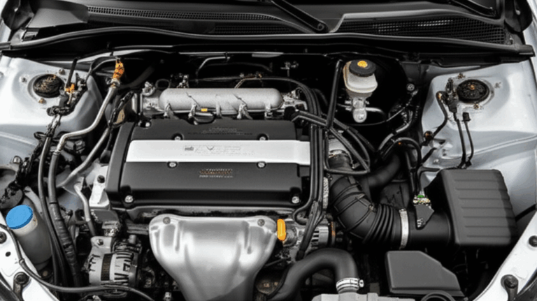
If you are staring at a no-spark problem or a stubborn cranking no-start condition you are not alone. Engineers and technicians run into ignition timing gremlins all the time and the culprit often hides in plain sight. The stator pickup coil. This small trigger device sits near the flywheel and quietly tells the ignition system exactly when to fire the spark plug. When it fails everything else suffers. Performance drops. Engines stall. Troubleshooting gets messy.
In this guide I will explain what a stator pickup coil does how it works why it fails and how to test it with confidence. I will also connect the dots between pickup coils and the stator assembly as a whole including motor laminations and magnetic materials because the mechanical design and materials around the coil shape the magnetic field it sees. That matters to ignition reliability and to your design and purchasing choices.
Before we dive in here is a quick map of what we will cover.
In This Article
- Problem: No Spark or Unstable Timing? Start With the Pickup Coil
- What Exactly Is a Stator Pickup Coil?
- How a Stator Pickup Coil Works: Electromagnetic Induction in Plain English
- The Pickup Coil’s Role in the Ignition System
- Symptoms of a Failing Stator Pickup Coil
- How to Test a Stator Pickup Coil
- Pickup Coil vs. Crankshaft Position Sensor
- Manufacturing Context: Stators, Laminations, and Why Materials Matter
- Maintenance and Troubleshooting Tips
- Practical Data: Failure Modes, Testing Accuracy, and Costs
- Which Application Is This For?
- Your Engineering Takeaway
Problem: No Spark or Unstable Timing? Start With the Pickup Coil
When an engine cranks yet refuses to start you often see three common patterns.
- No spark at all at the spark plug
- Intermittent spark or misfire at specific RPM ranges
- Hard starting when hot or random stalls after warm-up
These symptoms scream timing signal trouble. The stator pickup coil also called a pulse coil pulsar coil or trigger coil generates the timing pulse for the ignition control unit. If that pulse goes missing the ignition coil never fires. If it arrives late or distorted the spark plug fires at the wrong time and the engine runs rough.
You might be tempted to swap the CDI box the ignition coil or the spark plug first. Hold that thought. The pickup coil is cheaper easier to test and more likely to fail from heat vibration or insulation breakdown. Start with the simple checks first. It saves time and it saves money.
What Exactly Is a Stator Pickup Coil?
Definition and Alternative Names
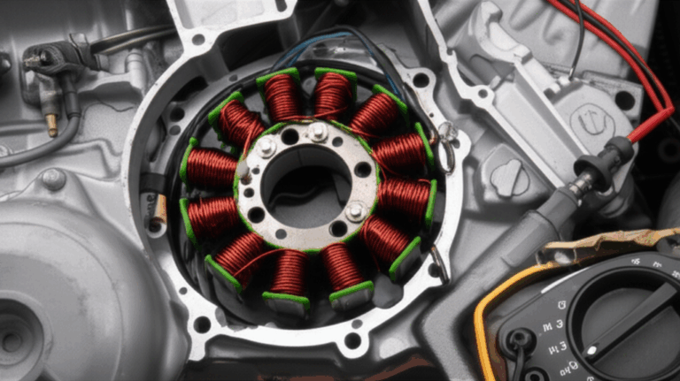
A stator pickup coil is a small magnetic pickup sensor that detects flywheel position and produces a low voltage AC pulse each time a timing feature passes by. You will also see it labeled as a pulse coil pulsar coil trigger coil or pulse generator coil. In electronic terms it is a variable reluctance sensor that responds to changes in magnetic flux.
Where You Will Find It
- Location: Typically mounted on the stator assembly very close to the flywheel or a reluctor wheel on the crankshaft
- Gap: Set with a small air gap to the flywheel magnets or steel timing lug
- Applications: Motorcycle ATV small engine outboard boat engine lawn equipment portable generator and older automotive or marine magneto ignition systems
In many designs the pickup coil sits on the same plate as the charging system coils and the exciter coil that feeds the CDI box. That is why people sometimes confuse the pickup coil with “the stator.” The stator assembly holds several coils that serve different jobs. The pickup coil only makes the timing signal.
How a Stator Pickup Coil Works: Electromagnetic Induction in Plain English
Faraday’s Law and the Magnetic Pickup Sensor Principle
Electromagnetic induction drives everything here. When a magnetic field through a coil changes the coil sees a voltage. That is Faraday’s Law. In a pickup coil the magnetic field changes because a moving magnet or steel tooth on the flywheel passes the coil face. This changing magnetic field induces a brief AC pulse. The direction and strength of that pulse depend on how fast the field changes and on coil winding construction.
Think of it like a guitar pickup that senses a vibrating string. As the steel string moves through the pickup’s magnetic field the pickup generates a tiny voltage that mirrors the motion. Your stator pickup coil sees a moving magnetic field from the flywheel rather than a moving string yet the principle is the same.
Flywheel Magnets, Reluctor Wheels, and Timing Marks
The flywheel on a magneto carries permanent magnets. As the flywheel spins those magnets sweep past the stator pickup coil and other coils. Some engines use a reluctor wheel with a tooth a slot or a steel timing lug that passes the pickup. Either way the pickup coil sees a sharp change in flux at a specific crank angle near top dead center. That timing mark on the flywheel or reluctor wheel tells the ignition where the piston sits. The result is a repeatable trigger signal that locks in spark plug timing.
The Signal: AC Pulse Generation and Output Voltage
- Output Type: Low voltage AC pulse often a single positive then negative blip
- Pickup Coil Output Voltage: Typically in the 0.5 V to 2.0 V AC range during cranking depending on design
- Signal Generation Process: Faster RPM leads to stronger pulses because the magnetic field changes faster
- Electrical Details: The pickup has a specific pickup coil resistance measurable with an ohmmeter. You can also see the pulse on an oscilloscope for deeper analysis.
For final control the ECU CDI or ignition control unit measures pulse timing and sometimes pulse width. The module then computes ignition advance based on engine RPM sensing and other inputs.
The Pickup Coil’s Critical Role in the Ignition System
Sending the Signal to ICU, CDI, or ECU
The pickup pulse heads straight to the ignition control unit. That might be:
- A CDI box in many small engines motorcycles ATVs and outboards
- An ECU in modern EFI engines that blends ignition control with fuel injection timing
- An older ignition module or ICU in classic automotive systems
The module treats the pickup as an ignition timing sensor or trigger signal. Lose the signal and you lose spark.
Ignition Timing, Spark Generation, and Engine Performance
- Ignition Timing: The control unit uses the pickup coil pulse to set when to fire the ignition coil and spark plug in relation to top dead center
- Spark Generation: In CDI systems the exciter coil charges a capacitor and the pickup coil triggers discharge through the ignition coil
- Ignition Advance System: The control unit advances timing as RPM increases. Stable pulses equal stable timing
- Engine Performance: Clean pulses translate to crisp starts steady idle smooth acceleration and better fuel economy. Bad timing hurts power can cause engine stalls and can contribute to pre-ignition or detonation under load.
On the charging side the stator has separate windings that feed the regulator/rectifier to charge the battery. The pickup coil does not charge the battery. It only triggers the spark.
Symptoms of a Failing Stator Pickup Coil
You can spot a bad pickup coil by how the engine behaves.
- No Spark: The most definitive sign. No timing pulse means no spark. Result is a cranking no start
- Intermittent Spark or Misfires: Weak or erratic pulses cause engine misfire and hesitations. You may see intermittent spark pickup coil symptoms that appear only at certain temperatures or RPM
- Hard Starting or No Start: The engine cranks yet does not catch or it starts only after prolonged cranking
- Engine Stalls Unexpectedly: Hot soak stalls are common with heat related failure pickup coil issues
- Poor Engine Performance: Rough idle surge poor acceleration or idle problems ignition that mimic fuel issues
- DTCs in ECU Vehicles: Modern systems may log a Diagnostic Trouble Code related to crankshaft position sensor or timing when the trigger signal goes intermittent
If these symptoms pop up after a long ride on a hot day or after vibration from off-road use you should suspect insulation degradation partial winding breaks or wiring harness damage symptoms near the engine.
How to Test a Stator Pickup Coil
You can test a pickup coil quickly with a multimeter. Bring a cool head and the service manual.
Safety and Tools
- Tools Required: Multimeter with ohms and AC voltage settings. An oscilloscope provides a deeper view but a DMM often suffices
- Safety First: Disconnect the battery where applicable. Keep hands clear of the flywheel and the rotor. Use proper grounding and avoid damaging insulation while probing connectors
Resistance Test With an Ohmmeter
This check finds open circuits short circuits and odd readings due to partial breaks.
A resistance check is fast. It catches most bad units yet it cannot verify dynamic signal quality under rotation.
AC Voltage Output Test While Cranking
If resistance passes run a live test.
You can run a stator output test for the charging coils separately. Keep in mind the pickup coil is not the same as the exciter coil or the charging coils.
Bonus: Oscilloscope and Timing Light
- Oscilloscope: Shows waveform shape polarity and jitter. You can confirm AC pulse generation and see distortion from a short circuit pickup coil or a weak magnetic transition
- Timing Light: With the engine running you can verify spark plug timing and ignition advance. If timing jumps erratically you may have an intermittent spark pickup coil issue or a failing ignition control unit
Pickup Coil vs. Crankshaft Position Sensor
You will hear people lump these together because both provide engine timing sensor data. They differ in construction and in where you find them.
- Similar Function: Both give the control unit precise crank angle information
- Pickup Coil vs Crank Sensor: Traditional pickup coils are variable reluctance sensors that make their own AC pulses from a moving magnet or tooth. Many modern crankshaft position sensor designs use a Hall effect sensor that outputs a clean digital square wave with power and ground
- Applications: Pickup coils remain common in magneto ignition systems on motorcycles ATVs small engine platforms and many marine engines. Crank sensors dominate modern automotive EFI engines and often pair with camshaft sensors to support sequential injection and coil pack function
In short a pickup coil does the ignition timing job in simpler magneto systems while a crank sensor handles timing and RPM in fully electronic engine management systems.
Manufacturing Context: Stators, Laminations, and Why Materials Matter
Engineers and procurement teams often focus on the pickup coil as a part number. Zoom out. The stator assembly function and the materials around the pickup coil affect magnetic field shape noise immunity and long-term reliability.
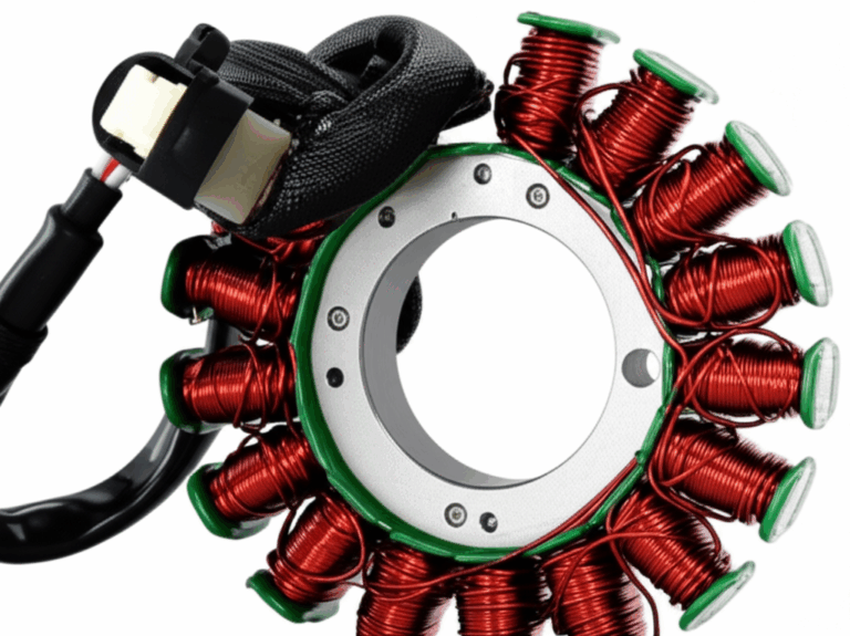
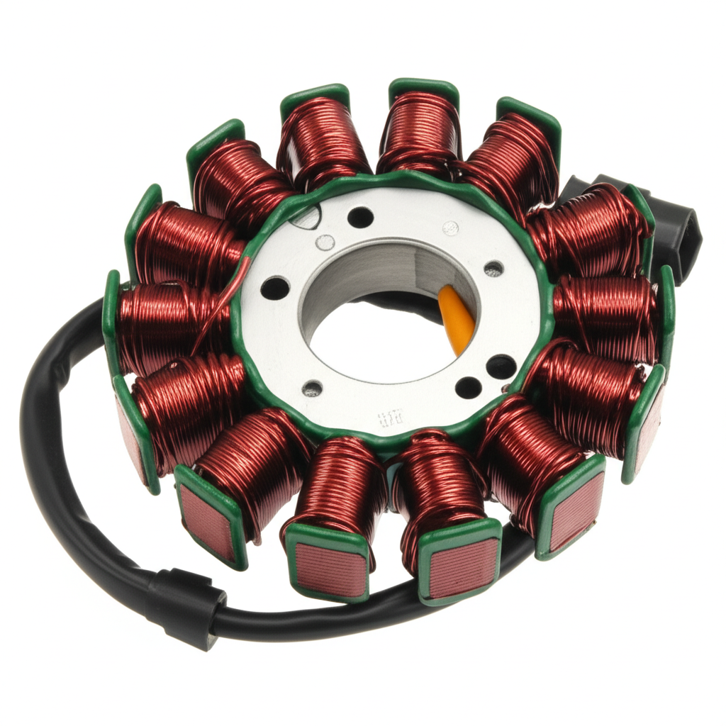
Stator Assembly, Core Laminations, and Magnetic Path
The stator sits inside or around a flywheel or rotor that carries the magnets. The steel behind the pickup and the nearby coil cores guide magnetic field lines. Quality lamination material and tight stator core lamination stacks stabilize the magnetic path which improves repeatability of the pulse.
- Electrical Steel Selection: High quality electrical steel laminations maintain magnetic permeability with minimal losses. Consistent flux paths translate to consistent signal amplitude at the pickup
- Motor and Rotor: The geometry and material of the flywheel or rotor also matter. A well-designed rotor core lamination controls leakage flux and helps maintain a crisp transition at the pickup face
- System View: The pickup coil shares the stator assembly with the exciter coil and charging coils. The core lamination stacks and the winding layout balance magnetic field priorities across charging and ignition
If you design or source stators remember that dimensional control of lamination stacks air gaps and coil positioning matters to trigger repeatability. Robust motor core laminations support stable flux density under thermal expansion and vibration.
Exciter Coil, Charging Coils, and the Regulator/Rectifier
In CDI systems the exciter coil function is to charge the CDI capacitor with high voltage AC which the CDI later dumps into the ignition coil. The pickup coil triggers that dump at the right crank angle. Charging coils feed AC to the regulator/rectifier function that converts AC to DC for the battery and electrical loads.
- Separation of Duties: Do not confuse exciter coil and pickup coil. The exciter creates energy for the spark. The pickup coil sets timing. The primary coil vs pickup coil comparison ends here because the ignition coil’s primary winding stores energy while the pickup does not
- Material Influence: Coil winding construction insulation choices and core steel grade affect output of both exciter and charging coils which indirectly affects ignition stability through voltage reserve and system EMI behavior
Tolerances, Insulation, and Vibration
Pickup coils fail mechanically more often than magnetically. Heat cycles harden insulation. Vibration fatigues lead wires. Oil contamination wicks into insulation and reduces dielectric strength. You can mitigate these with:
- High temperature winding insulation and robust potting
- Controlled routing of the wiring harness with strain relief to reduce vibration damage pickup coil
- Shielded cable or twisted pairs for noise rejection near strong AC fields from the stator coil output AC
Material and process control save you failures in the field and protect your reputation.
Maintenance and Troubleshooting Tips
Keep it simple and systematic.
- Visual Inspection: Check the pickup bracket position the air gap and the flywheel magnets or reluctor tooth condition. Look for corrosion or damage
- Clean Connections: Remove oxidation from connectors. Check continuity from the pickup to the ICU/CDI/ECU
- Harness Health: Inspect for chafing melted insulation and ground fault paths. Repair or reroute as needed
- Heat Management: Ensure engine cooling shrouds and ducts are intact. Overheating accelerates insulation degradation and causes heat related failure pickup coil
- Service Manual Importance: Always pull OEM data for resistance check stator coil specs and the correct pickup coil wiring diagram. Tolerance and polarity vary by model
If you work on automotive systems include a scan for DTC codes. Even if the engine uses a magnetic pickup sensor the ECU often reports timing correlation faults.
Practical Data: Failure Modes, Testing Accuracy, and Costs
Here is a consolidated view of field experience and common service data.
Note: Always use the OEM Service Manual for exact test values. Even within the same brand stator testing procedures and pickup coil resistance specs can differ.
Which Application Is This For?
Pickup coils show up across many platforms. The core physics do not change but the testing method or access might.
- Motorcycle: Common magneto ignition with CDI box function and a clear stator assembly under a side cover. A timing light and oscilloscopes help with advanced diagnosis. Motorcycle no spark troubleshooting often starts with the pickup coil and the kill circuit
- ATV All Terrain Vehicle: Similar to motorcycles with more environmental stress. Mud vibration and water ingress raise the odds of connection issues pickup coil and wiring harness damage symptoms
- Small Engine: Generators mowers and compact power units often use a simple magneto pickup coil and CDI. A generator pickup coil sits near the flywheel and uses an easy air gap setting
- Automotive: Older distributor or distributorless systems used VR pickup coils near a reluctor wheel. Modern systems use crankshaft position sensor and camshaft sensor combinations with either variable reluctance or Hall effect sensor operation. Coil pack function depends on the ECU timing signal which can be confused by a noisy pickup input
- Marine Boat Engine: Outboards often use CDI with a pulse coil. Salt environment highlights insulation and corrosion concerns. Marine pickup coil testing follows the same multimeter steps
- Industrial and Generator Sets: The principles remain the same. Consult the Service Manual for wiring diagrams and stator test values to keep units reliable under long duty cycles
The Engineering Fundamentals Behind Timing Quality
If your job blends design and sourcing you care about more than pass or fail. You care about field robustness and the repeatability of spark timing across production lots and operating temperatures.
- Magnetic Field Interruption: Clean edges in the magnetic field change give you crisp pulses. The shape and material of the timing lug or tooth matter
- Eddy Currents and Steel Grade: The stator backing behind the pickup experiences changing fields. Laminations break up eddy currents that otherwise waste energy and smear the magnetic transition in time. In other words thinner insulated laminations reduce magnetic lag and sharpen the pulse
- Faraday’s Law in Motion: Higher RPM sharpen signal amplitude yet the system must also produce a detectable pulse during slow cranking. Coil design and magnet strength set that floor
Standards like the IEC 60404 series cover magnetic material testing and they help you compare electrical steel datasheets. Lean on those when evaluating lamination material options.
Your Options Explained: Design, Materials, and Manufacturing
You have several levers to pull if you design or specify stator assemblies with pickup coils.
Material Considerations
- Electrical Steel Choices: Non-oriented silicon steels offer balanced magnetic properties that suit rotating machinery. Look for grades that offer stable permeability low core loss and good stamping behavior. At higher frequencies or in small packages material coercivity and thickness dominate eddy current loss behavior
- Lamination Thickness: Thinner laminations reduce eddy currents which helps stabilize flux transitions near the pickup. Very thin laminations raise manufacturing cost and can reduce stiffness so weigh the trade
- Insulation Coatings: Robust coatings maintain inter-laminar resistance which keeps eddy currents in check. They also protect against corrosion in humid or marine environments
- Magnet Material and Geometry: Flywheel magnet strength and layout influence pulse amplitude. You want enough field strength to meet pickup coil output voltage targets during slow cranking without excessive EMI at high RPM
Manufacturing and Assembly Processes
- Stamping vs Laser Cutting: Stamping offers high volume and low part cost with good burr control if the tool is new. Laser cutting suits prototyping or complex shapes yet can create a heat affected zone that changes local magnetic properties unless carefully controlled
- Interlocking vs Bonding vs Welding: Interlocking laminations act like LEGO bricks and avoid thermal damage from welding. Bonded stacks provide high rigidity but add process steps. Welding can degrade magnetic properties near the weld
- Tolerances on Air Gap: The pickup air gap to the reluctor or flywheel sets pulse amplitude. Define and measure it rigorously. Include parallelism and runout limits for the rotor
- Coil Winding and Potting: Even winding tension repeatable turns and high temperature potting compounds support long life under vibration and heat
Use design of experiments to balance pulse amplitude at cranking speed with noise margins at redline. Validate across temperature extremes since magnet strength and steel behavior shift with heat.
Maintenance and Troubleshooting Tips
A quick checklist you can use in the field or share with your service partners.
- Verify the Basics: Battery voltage where applicable good grounds kill switch state and clean connectors
- Air Gap Check: Measure the pickup to flywheel or reluctor gap. Adjust to OEM spec
- Resistance and Continuity: Perform an ohmmeter pickup coil test. Confirm continuity from the pickup through the wiring harness to the control unit. Look for ground fault or insulation nicks
- AC Pulse During Crank: Run a multimeter pickup coil test on AC volts while cranking. If numbers look low inspect flywheel magnets and look for oil contamination pickup coil faces
- Compare With Manual: Always consult the OEM Service Manual for stator testing procedures and exact specs. Do not guess. Some engines invert signal polarity or use a specific reluctor pattern
- Consider Heat: If it fails hot then works cold it likely is an intermittent resistance issue or partial winding break. Heat cycling reveals it
Case-Based Practical Insights and Failure Analysis
Let us tie symptoms to root causes.
- Engine Misfire Pickup Coil: A marginal pickup can create random miss events that look like fuel problems. Scope the signal while lightly tapping the harness. If jitter appears you likely found a broken strand inside the insulation
- Engine Stalls Causes: If the engine stalls when you snap the throttle and restarts after a cool down suspect a heat related failure of the pickup or the ICU module. Swap test if possible
- Poor Acceleration Diagnosis: Late or wandering spark timing can mimic clogged jets or weak fuel pumps. Verify ignition timing under load with a timing light if you can access the marks
- Fuel Economy Impact of Bad Timing: Late spark wastes fuel and raises exhaust temperature. Early spark under load courts detonation engine knock. Do not chase carburetors until you confirm timing stability
Practical Data: Failure Modes and Costs (Condensed Reference)
Already covered in the table above. Use it to set expectations with stakeholders during root cause reviews or warranty planning.
Which Application Is This For? Best-Fit Guidance
- Older Carbureted Engines: A pickup coil with a CDI box excels here. Keep the design simple and robust. Hall sensors add complexity without much benefit in this context
- Modern EFI Vehicles: Crank sensors with Hall effect or variable reluctance are standard. The ECU fuses timing with fuel control and coil pack function. Pickup coils appear mainly in legacy or small-engine fleets
- High Vibration Off-Road: Prioritize cable strain relief and potting compounds. Use generous bend radii and abrasion sleeves on the wiring harness
- Marine and Generator Duty: Target corrosion resistant connectors and moisture barriers. Seal grommets and consider conformal coating on exposed electronics
Honest Limitations
Pickup coils deliver analog signals that depend on speed and air gap. They produce weaker signals during cranking than at full speed. If your application needs clean digital edges at extremely low RPM consider a Hall effect sensor with a powered interface and a defined threshold.
Engineering References and Standards
- OEM Service Manuals: For wiring diagrams timing marks on flywheel and pickup coil resistance specs
- IEC 60404 Series: Magnetic materials test methods that inform electrical steel selection and characterization
- General Electromagnetics Texts: Faraday’s Law explanation magnetic field fundamentals and the electromagnetic induction principle
Use primary sources and component datasheets when you set acceptance criteria for a new platform.
Your Engineering Takeaway
- The pickup coil is the ignition timing sensor in magneto systems. It generates a small AC pulse as flywheel magnets or a reluctor tooth passes the coil
- The ignition control unit CDI or ECU reads that pulse to trigger spark plug firing and to compute ignition advance vs engine RPM
- Typical symptoms of a bad pickup coil include no spark intermittent spark misfires hard starting and hot stalls
- You can confirm health with two simple tests. An ohmmeter pickup coil resistance check and an AC voltage test while cranking. Verify against the Service Manual
- Failure modes cluster around open circuits intermittent heat failures and shorts due to insulation breakdown vibration and oil contamination
- The stator assembly and its laminations shape the magnetic field that the pickup senses. Material choice stack tolerances and rotor geometry matter to signal quality
- Choose materials and processes that stabilize flux paths reduce eddy currents and protect insulation. Control air gap and harness routing to boost reliability
- For modern EFI systems know when to use a crankshaft position sensor with Hall effect or variable reluctance instead of a passive pickup coil
If you are designing or sourcing stator assemblies or related ignition components and you want a second set of eyes on materials tolerances or test criteria reach out to your supplier’s engineering team for a technical review. Bring your specs your expected engine RPM range and your target timing stability. You will save rounds of trial and error and you will ship a more reliable product.
Keyword and Concept Index for Fast Scanning
To help you map this article to common terms you or your team might search while diagnosing or specifying parts I have included the core phrases addressed above.
- stator coil function and stator assembly function
- pickup coil purpose and trigger coil function
- how a pickup coil works and pulse coil operation
- pickup coil location relative to the flywheel and reluctor wheel
- stator pickup coil symptoms bad pickup coil symptoms
- how to test a pickup coil multimeter pickup coil test ohmmeter pickup coil test
- pickup coil resistance specifications pickup coil stator test values resistance check stator coil
- pickup coil output voltage AC pulse generation
- stator vs pickup coil primary coil vs pickup coil exciter coil function related to CDI
- ignition pickup coil charging system pickup coil
- motorcycle pickup coil ATV pickup coil small engine pickup coil automotive pickup coil marine pickup coil generator pickup coil
- crankshaft position sensor function pickup coil vs crank sensor Hall effect sensor operation magnetic pickup sensor principle
- flywheel magnets and timing marks on flywheel top dead center TDC sensor piston position and crankshaft
- ignition timing sensor spark plug timing ignition advance system engine RPM sensing
- engine misfire pickup coil no spark pickup coil intermittent spark pickup coil
- pickup coil wiring diagram types of pickup coils
- reluctor wheel rotor and flywheel
- CDI box function ignition control unit role engine control module ECM timing
- engine startup issues hard starting pickup coil cranking no start condition
- stator testing procedures stator output test
- open circuit pickup coil short circuit pickup coil intermittent resistance reading
- heat related failure pickup coil vibration damage pickup coil oil contamination pickup coil
- wiring harness damage symptoms connection issues pickup coil electrical diagnostics ignition troubleshooting ignition systems
- electronic ignition system parts magneto ignition system workings coil pack function spark energy generation
- engine performance issues related to timing engine stalls causes poor acceleration diagnosis idle problems ignition fuel economy impact of bad timing pre-ignition causes detonation engine
- engine management system sensors engine timing sensor definition magneto ignition timing stator coil output AC pulse generator coil trigger pickup coil
- regulator rectifier function battery charging system components ignition coil operation spark plug firing
- multimeter ohmmeter voltage resistance continuity ground fault open circuit short circuit
- timing light oscilloscope Diagnostic Trouble Code DTC Service Manual
- Motorcycle ATV Small engine Boat engine Generator
- Stator Pickup coil CDI ECU Flywheel Magneto Ignition system Charging system Engine timing Spark plug Ignition coil Crankshaft position sensor Hall effect sensor Magnetic pickup sensor Reluctor wheel Rotor Multimeter Ohmmeter AC DC Electromagnetic induction Faraday’s Law Voltage Resistance Continuity Ground fault Open circuit Short circuit Engine RPM TDC Piston Crankshaft Camshaft Engine management system Battery Regulator Rectifier Wiring harness Insulation Magnetic field Signal Pulse Timing light Oscilloscope DTC Service Manual Motorcycle ATV Small engine Boat engine Winding coil winding
This index echoes the content above so you can jump to sections relevant to your immediate need.
Final self-check of internal links:
- stator core lamination: used once
- electrical steel laminations: used once
- rotor core lamination: used once
- motor core laminations: used once
Total internal links: 4. All unique and used once each.