What Does a Stator Do? Understanding Its Core Function in Motors and Generators
Every design engineer and procurement manager runs into the same question sooner or later. What does a stator actually do, and how much does its lamination design matter to performance, cost, and reliability? You might be comparing motor types for a new pump line. Or you’re weighing hairpin windings vs round wire for an EV traction motor. Maybe you just need a clean, trustworthy explanation to align your team. You’re in the right place.
We’ll start with the plain-English definition, then dig into how stators work in motors and generators. We’ll explain why laminations exist, how they cut losses, and which materials or manufacturing routes fit which application. By the end, you’ll have the language and the checklist to make confident design and purchasing decisions.
In This Article
- What exactly is a stator? A foundational definition
- The stator’s primary function: creating the magnetic field
- How a stator works in motors and in generators
- Laminations 101: core losses, eddy currents, and hysteresis
- Material choices for stator cores and windings
- Manufacturing and stack assembly processes that move the needle
- Best-fit recommendations by application
- Why the stator is indispensable to efficiency and reliability
- Common stator problems and how to avoid them
- Your engineering takeaway and next steps
What Exactly Is a Stator? A Foundational Definition
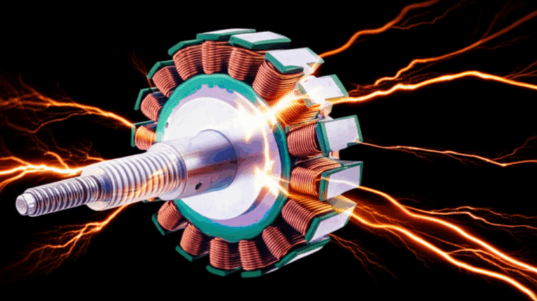
At heart, the stator is the stationary part of an electric motor or generator. It doesn’t spin. Instead, it creates and carries the magnetic field that the rotating part—the rotor—interacts with. Think of the stator as the “fixed stage” on which the electromagnetic action happens, while the rotor is the dancer.
- The stationary heart: The stator forms a rigid frame and a magnetic circuit. It provides slots to hold windings and a path for magnetic flux.
- Key components:
- Stator core: A stack of thin steel sheets—laminations—pressed together to form a magnetic core. The sheets are insulated from each other to cut eddy current losses.
- Windings (coils): Copper conductors placed in slots in the core. The windings connect to phases in AC machines or to a commutator/drive electronics in DC and BLDC machines. Insulation systems protect them from electrical stress and heat.
- Frame and housing: Provide mechanical rigidity, heat dissipation, and mounting features. In larger machines, the frame channels cooling air or liquid.
Stator vs rotor: The rotor is the rotating component. In an induction motor, the stator’s field induces current in the rotor to create torque. In a synchronous or BLDC motor, the rotor carries magnets or a wound field that locks to the stator’s field. In generators, the rotor cuts the stator’s magnetic field to induce voltage in the stationary windings.
If you remember one thing, remember this: the stator sets the magnetic stage, and the rotor performs on it.
The Stator’s Primary Function: Creating the Magnetic Field
Electromagnetism in action: Run electrical current through coils in the stator, and you create a magnetic field. Arrange the coils in groups—called poles—and you can control where north and south poles appear around the air gap. Reverse or alternate current and those poles move. This moving field is the workhorse in AC machines.
- The power of poles: More poles mean lower synchronous speed at a given frequency. Fewer poles mean higher speed. Synchronous speed depends on frequency (Hz) and pole count, which ties motor RPM to grid frequency or inverter output.
- Three-phase magic: A three-phase stator supplied with balanced AC creates a smooth rotating magnetic field. The field sweeps around the air gap, drags the rotor along, and produces torque. Single-phase stators can use auxiliary windings and capacitors to create a starting field then run with one phase.
- AC vs DC stators:
- AC stators generally use distributed or concentrated windings to generate a rotating field. Induction motors rely on this field to induce currents in the rotor.
- DC machines in classic form used a stationary field and a rotating armature. Modern brushless DC (BLDC) machines flip that arrangement. The stator holds the armature windings and electronic commutation creates a rotating field that permanent magnets on the rotor follow.
Engineers often talk about magnetic flux, back EMF, and power factor here. Flux is the “magnetic flow” through the core. When the rotor turns, it induces a voltage in the stator windings called back EMF that works against the applied voltage. Power factor captures how effectively current converts into useful power in AC systems, which depends heavily on how well the stator’s magnetic circuit is designed.
How a Stator Works in Different Electrical Machines
In Electric Motors: Turning Electricity Into Motion
Principle of operation: The stator generates a magnetic field that interacts with the rotor’s field. That interaction creates force across the air gap and torque on the rotor shaft. You convert electrical energy to mechanical energy.
- Induction motors: The stator’s rotating field induces currents in the rotor bars, which create their own magnetic field. The rotor lags the stator field slightly—this lag is called slip—and that difference drives torque. Induction motors are rugged and cost-effective, so you see them in pumps, compressors, fans, and conveyors.
- Synchronous motors: The rotor locks to the stator’s rotating field with no slip under steady load. The rotor either carries a DC wound field or permanent magnets. You get precise speed control and high efficiency. These motors show up in industrial drives, process lines, and high-end HVAC systems.
- Brushless DC (BLDC) motors: The stator holds the windings. The rotor carries permanent magnets. Power electronics switch the phases to create a rotating field that the rotor magnets chase. BLDC motors offer high power density and efficiency. You see them in drones, appliances, medical devices, and electric vehicles.
For BLDC designs, the geometry and insulation of the bldc stator core play a large role in torque ripple, acoustic noise, and thermal behavior.
In Generators and Alternators: Making Electricity
Principle of operation: Mechanical energy spins the rotor. As its field sweeps past the stator windings, it induces voltage per Faraday’s law. You convert mechanical energy to electrical energy.
- Alternators (AC generators): Produce alternating current. Automotive alternators use a wound rotor and a rectifier to supply DC to the battery. Utility generators in power plants use large stators with three-phase windings tied to the grid.
- DC generators (dynamos): Less common today. They use a commutator to convert AC induced in the armature into DC at the terminals.
Hydroelectric turbines, wind turbines, and backup gensets all lean on stator reliability. In large direct-drive wind turbines, the stator can weigh tens of tons. Failures are costly and hard to reach, so conservative design and rigorous manufacturing pay for themselves.
Laminations 101: Core Losses, Eddy Currents, and Hysteresis
Here’s where stators turn from a definition into an engineering decision. The core isn’t a solid lump of steel for a reason. AC fields would whip up circular “eddy currents” inside a solid core. Those currents waste energy as heat. Laminations fight that waste.
- Eddy currents, in plain English: Picture a river flowing around rocks. Big rocks create big whirlpools. In a solid core, the changing magnetic field creates big electrical whirlpools. Thin insulated sheets—laminations—act like a series of nets that break the big whirlpools into tiny ones that lose much less energy.
- Hysteresis loss: Magnetic materials resist changes in magnetization. Every time the field cycles, the material burns some energy to flip domains. That loss depends on material grade, frequency, and flux density. If you’ve heard of the B-H curve, that’s the graph of flux density vs magnetic field that shows how the material behaves.
- Stray load and additional losses: Slotting, harmonics, and mechanical construction add minor losses too.
Why lamination thickness matters: Thinner sheets reduce eddy currents, especially at higher frequencies. That’s why high-speed motors and generators trend to thinner laminations. This comes with cost and manufacturing trade-offs. For general-purpose motors on 50/60 Hz grids, common thickness ranges work well. For high-frequency machines—think high-speed compressors or aerospace actuators—you’ll look at thinner sheets, special coatings, or even different alloys.
Material science to the rescue: Add silicon to steel and you cut core losses while boosting resistivity. Use higher-purity base steel and optimized texture and you shape how magnetization moves. Non-oriented electrical steels serve motors and generators because they carry flux in multiple directions. Grain-oriented steels serve transformers because the flux path runs in one preferred direction.
Industry tests and standards such as IEC 60404, ASTM A677 for non-oriented electrical steel, and IEC 60034 for rotating machines set how we measure and document these losses. You don’t need every chapter memorized, yet you’ll want specs that map to widely recognized standards to keep sourcing open and comparable.
Material Choices for Stator Cores and Windings
Material selection isn’t one-size-fits-all. It’s closer to picking the right alloy for a turbine blade or the right resin for PCB potting. Define your duty cycle and environment. Then match material to physics and cost.
- Non-oriented silicon steels (M grades): The mainstream choice for motors and generators. Available in multiple thicknesses and grades. Balanced cost and performance at 50/60 Hz. Suitable up through medium frequencies with the right thickness and coatings.
- Cobalt-iron alloys: Higher saturation flux density and good strength at temperature. You get superior performance in high-power-density machines and high-speed rotors, yet you pay a premium. Aerospace and turbo machinery play here.
- Nickel-iron alloys: Useful in specialized magnetic circuits that call for high permeability and low coercivity. Less common in standard motors.
- Amorphous and nanocrystalline metals: Extremely low core loss at higher frequencies because the lack of crystalline structure slashes hysteresis. Excellent for transformers and some high-frequency motors. Manufacturing and cost can limit large-format adoption, yet you can’t ignore the loss reduction potential.
- Insulation coatings: The thin inorganic or organic layers on laminations matter. They control interlaminar resistance, punchability, and thermal class compatibility. They also influence bonding and stack methods.
- Copper windings: Oxygen-free or standard copper with enamel insulation. Hairpin windings raise slot fill factor up to roughly 70% in EV motors, which boosts current capacity and thermal performance. Round wire remains cost-effective and flexible in lower-volume or complex slot shapes.
If you’re new to sourcing, get familiar with the landscape of electrical steel laminations. Grades, coatings, and thickness options will define the performance and price envelope you can hit.
Manufacturing and Stack Assembly Processes That Move the Needle
How you cut and stack laminations changes magnetic loss, dimensional accuracy, vibration, and cost. This is where procurement and engineering need to sit at the same table early.
- Stamping: The workhorse for medium to high volume. Progressive dies stamp laminations fast with consistent geometry. Tooling costs more upfront but parts cost less at scale. Proper die design and maintenance minimize burrs that can increase loss or complicate stacking.
- Laser cutting: Ideal for prototypes, pilot runs, and complex geometries without the cost of hard tooling. Heat-affected zones can raise local loss, so process settings and post-processing matter. You get flexibility to iterate early in design.
- Wire EDM or waterjet: Niche processes for precise shapes or special alloys. Slow and expensive, yet extremely accurate, with minimal thermal impact.
- Stacking and joining:
- Interlocking: Tabs and notches snap laminations together like LEGO bricks. You get quick assembly without heat. Mechanical integrity depends on geometry and press fit.
- Welding: Solid structural integrity for rings and teeth. Local heat can affect magnetic properties. Use sparingly and away from high-flux regions when possible.
- Bonding: Adhesive-bonded stacks or backlack-coated laminations deliver strong, quiet cores with excellent interlaminar insulation. Great for acoustic performance and reduced vibration.
- Rivets and cleats: Traditional methods that still serve in certain designs and repair contexts.
- Insulation and impregnation: VPI (vacuum pressure impregnation) or resin potting locks windings in place, improves heat conduction, and raises resistance to moisture and vibration.
- Slot fill and thermal: Hairpin windings pack copper tightly for better heat removal and power density. They need precise slot geometry and reliable end-turn shaping. Round wire adapts more easily to narrow teeth and skewed slots.
When you hear people talk about premium efficiency motors (IE3/IE4), remember this. The gain often comes from better steel, thinner laminations, improved winding fill, and refined manufacturing to cut eddy and hysteresis losses. Moving from a baseline M19 thickness to a thinner grade with a high-quality coating can be the difference between 90% and 96% efficiency in the right design envelope.
For a deeper dive into common configurations, it helps to scan typical motor core laminations, which showcase slot shapes, tooth profiles, and stack strategies used across industries.
Best-Fit Recommendations by Application
Not all stators face the same battlefield. Match material and process to duty, speed, frequency, and cost targets.
- Pumps, fans, and compressors on the grid:
- Motor type: Three-phase induction or synchronous reluctance for premium efficiency.
- Material: Non-oriented silicon steel with thickness matched to 50/60 Hz operation.
- Process: Stamping for volume, interlocking or bonding for quiet operation. VPI for robust insulation.
- Notes: Specify IE3 or IE4 targets. Consider inverter-ready insulation for VFD drives to handle switching transients and dv/dt.
- Electric vehicles (traction motors):
- Motor type: Permanent magnet synchronous or BLDC for high power density. Some OEMs push induction or wound-field synchronous for rare-earth independence.
- Material: High-grade silicon steel or cobalt-iron for extreme power density. Hairpin windings for high slot fill. Thermal class H insulation in hot environments.
- Process: Precision stamping or laser for prototypes, bonded stacks for NVH control. Consider skew and step-skew stator teeth to cut torque ripple.
- Notes: Pay close attention to demagnetization risk in magnets, back EMF at high RPM, and inverter switching frequency. NVH targets drive tooth geometry and bonding choices.
- Aerospace and high-speed turbomachinery:
- Motor type: High-speed permanent magnet or induction motors running at high frequency.
- Material: Thin laminations and potentially cobalt-iron. Tight tolerances and balancing.
- Process: Low-loss cutting process, bonded stacks. Excellent thermal paths and high-integrity impregnation.
- Notes: Certification requirements and temperature extremes raise the bar on materials and QC.
- Wind turbines and hydroelectric generators:
- Generator type: Large-diameter, multi-pole alternators. Direct drive or geared.
- Material: High-grade non-oriented steel. Robust insulation and thermal management.
- Process: Bonded or welded where structurally necessary, with careful heat control. Field winding designs for excitation systems where used.
- Notes: Downtime is expensive. Design for maintainability and long life. Condition monitoring helps.
- Household appliances:
- Motor type: BLDC and single-phase induction in cost-sensitive markets.
- Material: Cost-optimized silicon steel. Round wire windings or hairpin in premium segments.
- Process: Stamping and interlocking. Automated winding and impregnation.
- Notes: Focus on acoustic noise, efficiency regulations, and compact packaging.
- Automotive alternators:
- Generator type: Compact alternators delivering high current at idle speeds.
- Material: High-strength laminations with efficient slot designs. Robust rectification and thermal management.
- Process: High-volume stamping. Efficient cooling pathways.
- Notes: Heat, vibration, and lifetime loads drive insulation and mechanical design.
If your product roadmap leans toward compact BLDC motors, the construction of the stator core lamination will determine torque density, core loss, and acoustic signature as much as your magnet choice does. Don’t forget the rotor side of the ledger either. Rotor bar geometry, magnet grade, and rotor core lamination construction lock in ripple and efficiency too.
Why the Stator Is Indispensable to Efficiency and Reliability
You can think of the stator as the backbone of energy conversion. It shapes the magnetic circuit, which sets the stage for torque production or voltage generation. Stator design and material choice directly affect:
- Efficiency and power output: Lower core losses and higher slot fill push you toward IE3/IE4 territory. Industry data shows well-optimized stators contribute to motor efficiencies in the 90–96% range for premium models.
- Thermal management: Lower losses mean less heat, which extends insulation life and bearing life. Hot machines fail faster.
- Power factor and reactive power: Better magnetic design and control strategies cut reactive power draw and improve grid friendliness.
- Structural integrity: The stator frame and stack hold the machine together. Mechanical rigidity affects vibration and noise, which affects lifetime and customer perception.
In reliability studies, stator winding failures often make up 30–40% of motor failures in industrial applications. Insulation breakdown, inter-turn shorts, and phase-to-ground faults are common culprits. Vibration, contamination, thermal cycling, and voltage spikes accelerate them. That’s why material selection and processes like impregnation aren’t just “manufacturing details.” They’re reliability levers.
Common Stator Problems and How to Avoid Them
Most stator failures trace back to one of a handful of root causes. Good design and supplier discipline can prevent them.
- Overheating:
- Cause: Excess core loss, high copper loss from undersized conductors or poor slot fill, blocked cooling, or ambient heat.
- Fix: Better steel grade or thinner laminations. Improve slot fill. Upgrade insulation class. Revisit cooling design. Validate with temperature rise tests per IEC 60034 or IEEE Std 112 methodologies.
- Insulation breakdown:
- Cause: Thermal aging, contamination, partial discharge in high-voltage windings, inverter-induced voltage spikes, moisture ingress.
- Fix: Choose the right insulation class and VPI or resin system. Add surge protection or dv/dt filters for VFDs. Seal against moisture and dust. Implement routine insulation resistance and polarization index tests.
- Winding shorts (inter-turn or phase-to-phase):
- Cause: Mechanical abrasion, hot spots, manufacturing defects, or severe transients.
- Fix: Improve slot liners and coil support. Tighten process controls. Use surge testing during production. Monitor vibration to reduce fretting.
- Open circuits:
- Cause: Broken leads, poor terminations, or thermal cycling fatigue.
- Fix: Robust lead dress, strain relief, and crimp/weld quality checks.
- Vibration and noise:
- Cause: Magnetostriction, slot harmonics, imbalance, or loose stacks.
- Fix: Optimize tooth/slot geometry and skew. Bond stacks. Balance rotors to tighter tolerances. Validate with NVH testing.
- Core damage:
- Cause: Burrs that bridge laminations, welding heat in flux paths, or shorted laminations.
- Fix: Control burr height in cutting. Place welds away from high-flux regions. Use bonding for low noise and high integrity.
Predictive maintenance helps too. Temperature, vibration analysis, and partial discharge monitoring catch many issues early. Tie that data back to design assumptions and you’ll improve the next generation.
The Business Side: Cost, Sourcing, and Risk Management
Procurement cares about more than physics. You have budgets, timelines, and supply risks to manage.
- Total cost of ownership: Energy dominates lifetime cost for many motors. A small premium for better laminations and slot fill can pay back fast in lower electricity bills.
- Tooling and volumes: Stamping dies raise NRE costs but cut piece price at volume. Laser stays flexible for low volume and frequent design changes. Don’t lock into tooling until performance and manufacturability stabilize.
- Second sourcing: Specify materials and coatings by widely recognized standards and ranges, not by a single supplier SKU. You keep the door open for competitive bids and supply resilience.
- Quality systems: Ask about ISO 9001 and process controls. Traceability for lamination batches and insulation systems protects you in the field.
- Compliance: Check efficiency standards in your markets and any application-specific safety regulations. HVAC, automotive, and aerospace all carry extra requirements.
This is where a brief look at publicly available examples of core lamination stacks can help your team visualize assembly options and discuss trade-offs early.
Engineering Fundamentals Recap: Short Answers to Common Questions
- Why laminations, not a solid core?
- To reduce eddy current loss that would otherwise overheat the core and waste energy.
- Do thinner laminations always win?
- Thinner usually reduces loss at higher frequency. They also cost more and can complicate manufacturing. Match thickness to frequency and performance needs.
- Is grain-oriented steel better?
- For transformers, yes. For motors and generators with rotating fields, non-oriented steels are the norm.
- What’s the best winding strategy?
- It depends. Hairpins can boost slot fill and power density in EV motors. Round wire stays versatile and cost-effective for many industrial designs.
- How do I link frequency and speed?
- Synchronous speed rises with frequency and drops with more poles. In induction motors, rotor speed sits just below synchronous speed by a small slip percentage.
Which Specs Should You Lock Down First?
Engineers and buyers avoid churn when they align around a compact set of decisions early.
- Electrical: Voltage, frequency or inverter range, number of phases, target efficiency, power factor target, torque-speed curve, and duty cycle.
- Mechanical: Shaft speed and load profile, gear ratio if any, envelope size, mounting geometry, and cooling method.
- Thermal and environment: Ambient temperature, altitude, ingress protection, humidity, and thermal class.
- Materials: Target lamination grade and thickness range, insulation system, slot liner class, and winding strategy.
- Compliance and testing: Efficiency class (IE2/IE3/IE4), standards for testing and labeling (IEC 60034, IEEE Std 112), and any vertical market requirements.
Document these, then engage your lamination and winding suppliers while changes are still cheap.
Your Engineering Takeaway and Next Steps
Here’s the short version you can share with your team.
- The stator is the stationary magnetic heart of motors and generators. It creates or carries the magnetic field that the rotor interacts with to produce torque or voltage.
- Laminations exist to cut core losses. Thinner insulated sheets break up eddy currents and reduce heat, especially at higher frequencies.
- Material choice drives performance. Non-oriented silicon steel covers most motors and generators. Cobalt-iron and amorphous alloys unlock high-speed or high-frequency performance at higher cost.
- Manufacturing matters. Stamping fits volume. Laser supports prototypes and complex designs. Bonded stacks and careful cutting reduce noise and losses.
- Application fit beats rules of thumb. Pick material and stack strategy to match duty cycle, speed, frequency, and cost targets.
- Reliability comes from details. Insulation system, impregnation, burr control, and thermal paths decide lifetime and downtime.
- Business outcomes count. Premium stator designs lift efficiency to the 90–96% range in many motors, which cuts lifetime energy costs and boosts competitiveness.
Actionable next steps:
- Define your performance envelope: voltage, frequency, poles, torque-speed, duty, and thermal limits.
- Set a target efficiency class and acoustic target. Decide if VFD operation is a requirement.
- Shortlist lamination materials and thickness ranges based on frequency and form factor. Align with recognized steel and coating standards.
- Choose a prototyping path: laser-cut laminations for early builds, then transition to stamping when the design stabilizes.
- Engage suppliers early. Share slot geometry, fill factor goals, and insulation class so they can recommend stack assembly and impregnation processes.
- Build a test plan aligned to IEC/IEEE standards. Validate temperature rise, efficiency, vibration, and partial discharge if applicable.
If you need a quick way to compare common lamination families and stack configurations for your application, review examples of stator core lamination and motor core laminations to spark the right design conversations.
Conclusion: The Quiet Powerhouse Behind Our Modern World
You’ll find stators everywhere. In EV drivetrains, HVAC blowers, wind turbine nacelles, factory conveyors, and your kitchen blender. They don’t move, yet they make everything else move. Their laminated cores, windings, and frames convert energy with a quiet efficiency that hides a lot of physics and even more engineering.
Design them well and you produce more torque per kilogram, run cooler, and last longer. Cut corners and you pay for it in energy bills, noise, and downtime. That’s the real answer to “what does a stator do.” It doesn’t just make a motor spin or a generator produce voltage. It sets the ceiling for performance, efficiency, and reliability across the entire machine.
Ready to turn this understanding into a better design? Share your constraints, define your targets, and loop in your lamination partner early. A few clear choices now save months later, and they often add years of service life in the field.