What Does a Stator Do on a Motorcycle? An Engineer’s Guide to Function, Materials, and Manufacturing
If you are diagnosing a “battery not charging” problem or you are designing a charging system for a new platform, you are asking a simple question with big implications. What does a stator do on a motorcycle, how does it work with the regulator/rectifier, and which materials or manufacturing choices actually change performance and cost? That is the right problem to focus on. The stator sits at the heart of the motorcycle charging system. It generates the raw electrical power that your regulator/rectifier converts to stable DC for the battery and every electrical load on the bike.
You need a clear picture of both the electrical function and the mechanical stack that makes it possible. Engineers care about output, thermal headroom, lifetime, and cost. Procurement teams care about processes, tolerances, and reliable supply. Let’s cover it all in one place.
In This Article
- Why the Stator Matters in a Motorcycle Charging System
- The Electrical Ecosystem: Stator, Rotor, Regulator/Rectifier, Battery
- What the Stator Is and Where It Lives
- How a Stator Generates AC Power and How the R/R Makes DC
- What the Stator Powers on a Motorcycle
- Symptoms of a Bad Stator and Common Root Causes
- DIY Troubleshooting: Multimeter Tests That Actually Help
- Lifespan, Replacement, and Maintenance Tips
- Engineering Fundamentals: Laminations, Eddy Currents, and Core Loss
- Material Choices for Stator Laminations and When to Use Them
- Manufacturing Processes That Affect Cost and Performance
- Best-Fit Guidance by Application and Duty Cycle
- Procurement Considerations and Cost Drivers
- Your Engineering Takeaway and Next Steps
Why the Stator Matters in a Motorcycle Charging System
Problem
- Riders report dim headlights at idle and a “battery warning light” at speed. The bike stalls then refuses to start. Engineers see warranty returns that point to heat-damaged windings and a failed regulator/rectifier. Procurement teams see a spread in quoted costs for ostensibly similar “stator assemblies.” The question behind all of this is the same. What does the stator do and which decisions upstream reduce risk and cost down the line?
Explain
- The stator is the stationary part of a small alternator bolted to the engine. Magnets pass the copper windings as the crankshaft turns. That motion induces AC voltage in the coils. The regulator/rectifier converts that AC to DC and holds voltage in a safe window for the battery and loads.
Guide
- We will unpack the electrical basics, show you what typically fails, and then step into design choices that move the needle. Lamination material, thickness, insulation, and manufacturing processes change efficiency and durability.
Empower
- You will leave with a short checklist for diagnosis, a material selection framework, and practical process trade‑offs you can take to a supplier.
The Electrical Ecosystem: Stator, Rotor, Regulator/Rectifier, Battery
A motorcycle charging system is simple on paper yet unforgiving in the field.
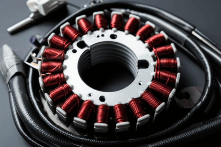
- Stator: a laminated iron core with copper coils that generate AC.
- Rotor/flywheel: a ring of permanent magnets keyed to the crankshaft that spins past the stator poles and produces changing magnetic flux.
- Regulator/Rectifier (R/R): diodes convert AC to DC, a regulation circuit clamps voltage.
- Battery: stores energy and smooths demand.
Everything is a loop. Engine speed raises stator output which feeds the R/R. The R/R supplies the battery and the bike’s loads. A weak battery makes the R/R and stator work harder. Poor regulation overheats the stator. Bad connections increase resistance and waste power as heat.
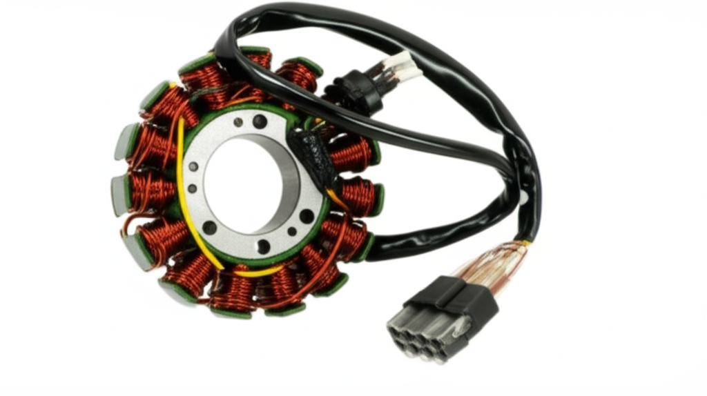
What the Stator Is and Where It Lives
At its core, the stator is a stack of thin electrical steel laminations with copper wire windings around the teeth. The laminations form a magnetic circuit that guides flux around the coils. The stack is typically housed behind an engine cover on the left or right side. Many designs immerse the assembly in engine oil for cooling. You will also find air‑cooled variants that rely on airflow over the cover.
Anatomy at a glance
- Laminated iron core: thin sheets reduce eddy current losses and focus flux.
- Copper windings: enamel‑insulated magnet wire wound on each tooth.
- Slot insulation and varnish: prevent turn‑to‑turn shorts and aid heat transfer.
- Leadouts and connector: three‑phase output on most modern bikes.
- Gasketed cover: keeps oil in and contamination out.
If you want to go deeper on the steel stack itself, the quality of the stator core lamination directly affects core loss, heat, and output stability at high RPM.
How a Stator Generates AC Power and How the R/R Makes DC
This is Faraday’s Law in action. A changing magnetic field induces a voltage in a conductor. As the rotor’s permanent magnets sweep past the stator teeth, magnetic flux through each coil rises and falls. That time‑varying flux induces an alternating voltage. Most motorcycles use three‑phase stators because three phases provide smoother power and better efficiency.
Key points for engineers
- Stator output is unregulated AC. Expect roughly 20–30 VAC per phase at idle and proportionally more with RPM. Check the service manual for your model’s specification.
- The R/R rectifies and regulates. You should see 13.5–14.5 VDC across the battery terminals at 2,000–3,000 RPM on a healthy system.
- Permanent magnet generators cannot “turn down” field strength like automotive alternators. Excess power becomes heat that the R/R and the stator must shed.
The physics in one analogy
- Think of magnetic flux like water moving through a pipe network. The laminations shape the pipes. The magnets act like a pump that cycles pressure. The copper coils sit where the flow changes the most. That change creates electrical pressure, which is the voltage you measure.
What the Stator Powers on a Motorcycle
Without a working stator your battery becomes a timer. When it runs out the show ends. With a working stator the system powers:
- Ignition system and spark plugs, ECU, fuel injectors, and the fuel pump.
- Headlights, tail lights, turn signals, brake lights, and ABS where fitted.
- Instrument clusters, sensors, and safety systems like traction control.
- Accessories like heated grips, USB chargers, navigation, and auxiliary lighting.
You will also see a weak stator show up as “engine struggling” at idle, misfires under load, or “headlights dimming at idle.” Those are clear diagnostic flags that tie directly back to power generation and regulation.
Symptoms of a Bad Stator and Common Root Causes
When the stator loses output the entire charging system suffers. Watch for these:
Battery related
- The battery dies repeatedly. You jump it then it dies again after the ride.
- Slow cranking and difficulty starting after short trips.
- A charging system or battery warning light on bikes that monitor voltage.
Performance and lighting
- Dimming headlights and dash lights at idle that brighten with throttle.
- Engine misfires, rough running, or stalling as voltage sags under load.
- Weak spark that makes hot restarts difficult.
Other clues
- Electrical burning smell, discolored windings, or melted connectors.
- Abnormal multimeter readings: low AC output, phase imbalance, resistance not matching spec, or any continuity from a stator lead to ground.
Why stators fail in the real world
- Overheating is the big one. High current at high RPM generates I²R losses in the windings and core losses in the laminations. Weak regulation forces the stator to dump more heat. Poor oil flow makes it worse on oil‑cooled designs.
- Insulation breakdown. Varnish and slot liners age under heat which leads to turn‑to‑turn shorts and reduced output.
- Connector corrosion and poor grounds. Resistance rises which makes heat which accelerates failure.
- Faulty regulator/rectifier. A failing R/R overworks a healthy stator which then fails early.
DIY Troubleshooting: Multimeter Tests That Actually Help
You can separate a stator fault from an R/R or battery problem with a digital multimeter and a few quick checks. Always consult the service manual for pinouts and specs for your model.
Tools
- Digital multimeter with AC voltage, DC voltage, resistance (Ohm), and continuity modes.
- Battery load tester if available.
- Basic hand tools to access connectors.
Sequence
1) Battery baseline
- Key off battery voltage should rest around 12.6–12.8 V for a healthy battery at full charge.
- Key on then crank. If voltage plunges below 10 V your battery may be weak. Load test it to remove the battery as a variable.
2) Charging voltage at the battery
- Start the engine then measure DC voltage at 2,000–3,000 RPM. Expect 13.5–14.5 VDC. Low voltage here does not prove the stator is bad. It only proves the charging system is not meeting spec.
3) AC output test at the stator
- Unplug the three‑wire stator connector from the R/R. With the engine running measure AC voltage between each pair of the three stator wires. A typical three‑phase stator shows similar readings on all three pairs. Expect roughly 20–30 VAC per pair at idle then rising with RPM. A dead phase or a large imbalance points to stator trouble.
4) Resistance (Ohm) test
- With the engine off and the stator unplugged measure resistance phase‑to‑phase. Values are low, often 0.1–0.5 Ohm, and each pair should match within a small tolerance. Any open circuit indicates a broken winding. Any big mismatch suggests a partial short.
5) Continuity to ground
- Check each stator lead to engine ground. You should read open circuit. Any continuity to ground means a shorted coil or insulation failure.
6) R/R check
- If the stator passes the AC and resistance tests, test the regulator/rectifier per your service manual. Many modern R/R units fail under heat or load. A diode test on the rectifier bridge and a running DC voltage check can surface problems.
Pro tip
- Inspect connectors and grounds. Corrosion and loose pins cause voltage drop and heat. A clean harness may save you a stator.
Lifespan, Replacement, and Maintenance Tips
Lifespan varies widely. Some stators last the life of the bike. Many fail between 20,000 and 60,000 miles on heat‑stressed platforms or where the R/R runs marginal. Replacement cost ranges with displacement and complexity. Parts may run from roughly $80 on small scooters to $300–$600 or more on high output models. Labor can add $150–$500. Draining oil, removing covers, and resealing takes time.
Good habits extend life
- Maintain battery health. A weak battery makes the system run hot.
- Keep electrical connections clean and tight. Bad grounds are silent killers.
- Avoid sustained overload. Heated gear, lights, and accessories add up. Be honest about the alternator’s output budget.
- Monitor charging voltage a few times a season. A $20 meter can save a trip.
Engineering Fundamentals: Laminations, Eddy Currents, and Core Loss
If you design or source stators, the laminated steel stack is not a commodity detail. It drives efficiency, heat, and stability across the RPM range.
What is lamination and why it matters
- The stator core is not a solid ring. It is a stack of thin sheets with an insulating coating on each face. That insulation breaks up paths for eddy currents which are circulating currents induced by changing magnetic fields. Eddy currents waste energy as heat. Thinner laminations reduce these losses at a given frequency.
- Core loss has two main parts. Hysteresis loss comes from the energy cost to flip the magnetization of the steel each cycle. Eddy current loss comes from those induced loops. Frequency, flux density, and material properties set the scale.
A picture in words
- Eddy currents behave like little whirlpools in a river. Laminations act like rocks that break those whirlpools into tiny swirls that carry less energy. The result is less heat and more useful power.
Key terms with quick definitions
- Magnetic permeability: how easily a material carries magnetic flux. Think sponge soaking up water.
- Coercivity: the resistance to being demagnetized. Lower coercivity usually means lower hysteresis loss.
- B‑H curve: the relationship between magnetic flux density (B) and magnetizing force (H). The shape of this curve informs material choice and performance at your target flux levels.
Relevant standards to know
- ASTM A677 covers non‑oriented electrical steel for rotating machines.
- ASTM A683 covers grain‑oriented electrical steel for transformers which is not typical for rotating stators but useful for context.
- IEC 60404 outlines methods for measuring magnetic properties of electrical steel.
- IEC 60034 covers rotating electrical machines at the system level.
Material Choices for Stator Laminations and When to Use Them
Material selection is a balancing act. Cost, thickness, frequency, flux density, and temperature all matter. You are usually picking among non‑oriented silicon electrical steels in the 0.35 mm to 0.50 mm range for motorcycle alternators due to their RPM and thermal demands.
Common options
- Non‑oriented silicon steel (NOES): The workhorse. Good isotropy for rotating machines. Available in a range of grades with different losses and permeability. Thinner gauges lower eddy loss at higher frequency.
- High silicon content NOES: Offers lower core loss at higher frequencies though it may be more brittle in stamping and handling.
- Cobalt‑iron alloys: Excellent saturation and low loss at high flux density which supports high power density. They cost more so you deploy them only when the performance case is compelling.
- Powdered iron or soft magnetic composites: Useful for 3D flux paths though less common in traditional motorcycle stators.
Choosing thickness
- At typical engine RPM a motorcycle stator sees electrical frequencies that scale with pole count and speed. Higher pole count and high RPM push you toward thinner laminations.
- If your design runs hot or close to saturation, prioritize a low core loss grade to control temperature rise.
Insulation class
- The interlaminar insulation must survive oil exposure, temperature cycling, and vibration. The right coating reduces interlaminar shorts and preserves low eddy loss over time.
A simple framing
- If you need a robust general‑purpose solution for a three‑phase stator, start with a mid‑loss NOES grade in 0.35–0.50 mm then validate losses and temperature with your target rotor magnet set. If your loss budget misses at high RPM, consider a thinner gauge or a higher grade with lower loss.
If you want a broader view of the material family and form factors, see electrical steel laminations.
Manufacturing Processes That Affect Cost and Performance
The manufacturing route changes magnetic properties, dimensional accuracy, and cost. It also determines what defects show up in your warranty returns.
Stamping
- Best for volume with consistent geometry. Tooling cost is higher upfront yet part cost falls quickly at scale. Stamping introduces burrs and mechanical stress in the steel which increases core loss if not controlled. Use sharp tooling, burr control, and stress‑relief annealing when the grade and coating allow it.
Laser cutting
- Ideal for prototypes and low volume. Geometry flexibility is high with no hard tooling cost. Heat‑affected zones can raise local loss which matters more on high performance grades or very thin material.
Wire EDM
- Excellent edge quality and tight tolerance with minimal heat input. Slower and costlier for volume.
Stacking and assembly
- Options include interlocking features, riveting, welding, and bonding. Welding can raise local loss near welds. Mechanical interlocks act like LEGO bricks that snap together which avoids heat input. Bonding can improve stiffness and acoustic performance with even clamping across the stack.
Varnish and impregnation
- Proper impregnation improves thermal conduction from copper to steel and adds mechanical stability. It also protects windings from oil and vibration.
Quality levers that matter
- Control burr height. Burrs increase local saturation and loss. They also damage winding insulation.
- Verify lamination insulation integrity. Interlaminar shorts raise eddy loss and heat.
- Manage slot fill. Higher copper fill improves output yet raises thermal density. Find the balance your cooling can handle.
- Validate stack height tolerance. It changes tooth geometry and air gap which affects flux density.
For a consolidated view of core stack capabilities, you can reference motor core laminations.
Best-Fit Guidance by Application and Duty Cycle
Different motorcycles and duty cycles shift the target.
Commuter and middleweight bikes
- Goals: reliability, moderate cost, stable output across daily RPM bands.
- Approach: NOES at 0.35–0.50 mm with robust insulation and oil compatibility. Emphasize connector sealing and R/R reliability. Use three‑phase stators for smooth charging.
High performance sport and adventure bikes
- Goals: high power for lighting, ECU, ABS, heated grips, and accessories while idling in traffic and revving at speed.
- Approach: lower loss NOES or thinner lamination for better high RPM efficiency. Validate temperature rise in worst case heat soak. Consider improved heat paths in the cover and oil flow.
Heavy touring with accessories
- Goals: strong low RPM output for idle time with loads plus redundancy for long trips.
- Approach: more poles and refined winding layout to raise low speed output. Oversize the R/R and manage airflow. Monitor wire gauge and connector temperature margins.
Off‑road and enduro
- Goals: durability, water ingress protection, quick recovery after stalls.
- Approach: robust potting and sealing, conservative flux density, and connectors that tolerate dirt and vibration.
Rotor considerations
- Many motorcycle alternators use permanent magnet rotors. The steel behind the magnets still matters since it carries return flux. Matching the rotor’s back iron to the stator’s tooth design reduces leakage and harmonics. If your platform uses a laminated rotor core rather than a solid steel carrier, review rotor core lamination.
Procurement Considerations and Cost Drivers
If you are sourcing stators or components, align the print with realistic process capability and environmental requirements.
What to specify
- Material grade per ASTM or equivalent with thickness and coating type.
- Maximum allowable burr height and whether deburring is required.
- Post‑processing such as stress‑relief anneal while keeping insulation intact.
- Stack assembly method and allowed weld zones if applicable.
- Slot insulation class and varnish type with oil compatibility.
- Electrical tests: phase resistance tolerance, hi‑pot, surge test, and AC output spec at defined RPM.
- Environmental: target temperature rise at load, oil immersion requirements, vibration survivability.
Cost levers
- Tooling amortization vs volume. Stamping beats laser at volume by a wide margin.
- Lamination grade and thickness. Higher grades and thinner gauges cost more yet may save downstream cost by reducing failures.
- Winding method. Automated winding increases consistency at scale. Hand winding may suit service parts.
- Harness and connectors. High‑temp, sealed connectors cost more yet they reduce warranty claims on bikes exposed to weather.
Supplier conversations to have
- Ask for magnetic test data on the actual lot. Reference IEC 60404 methods.
- Review their deburr and stack processes. See sample edges and test pieces.
- Align on acceptance tests you will run at goods‑in and at end of line.
Practical Integration of SEO Topics for Clarity and Completeness
Engineers and technicians search the same topic in different words. Here is how the recurring phrases map to the engineering reality.
- “Motorcycle charging system explained” and “How motorcycle generates electricity”: The stator makes AC, the R/R makes DC, the battery buffers load. That is the generator working principle.
- “Alternator vs stator motorcycle” and “Stator vs magneto vs alternator”: On many bikes the alternator is a permanent magnet generator made of the rotor and stator. People call that assembly a magneto when it has self‑contained ignition. The stator is the stationary part either way.
- “Symptoms of a bad stator motorcycle” and “Motorcycle battery not charging”: Dead or weak battery, dim headlights at idle, misfires, and rough running are the day‑to‑day flags.
- “Testing motorcycle stator with multimeter,” “Open circuit stator test,” “Short circuit stator test,” and “Resistance check stator ohms”: Those map to the AC output test, phase‑to‑phase resistance, and isolation to ground. You can do all three with a DMM.
- “Three phase stator motorcycle” and “Single phase stator motorcycle”: Three‑phase dominates modern bikes for smoother and more efficient charging. Single phase appears on smaller or older platforms.
- “Regulator rectifier function motorcycle” and “Voltage regulation motorcycle system”: Rectifier diodes turn AC to DC. The regulator holds voltage near 14.0 VDC so you do not overcharge the battery.
- “Heat damage stator motorcycle,” “Oil cooled stator design,” and “Air cooled stator issues”: Heat kills windings and insulation. Oil bathing helps if flow is adequate. Air cooled covers need good finning and airflow.
- “Wiring harness issues,” “Grounding issues motorcycle electrical,” and “Voltage spike motorcycle damage”: Poor connections raise resistance and create spikes that stress the R/R and ECU. Healthy grounds keep noise and spikes down.
- “Aftermarket stator motorcycle reviews” and “OEM stator motorcycle parts”: Quality varies. Verify wire gauge, insulation quality, and lamination stack integrity. Cheap parts that last one summer cost more over time.
- “Stator upgrade options,” “High output stator motorcycle,” and “Performance motorcycle stator”: Higher pole counts, improved copper fill, and lower loss laminations raise output. Validate the R/R and wiring thermal capacity before you drop one in.
“Which Application Is This For?” A Quick Fit Guide
- You need strong charging at idle for city bikes with heated grips. Consider more poles and a winding scheme that shifts output toward low RPM. Validate copper temperature rise in oil soak.
- You design a high RPM sport engine where the alternator sits inside the crankcase. Choose a lower loss NOES with thinner laminations and robust slot insulation. Use impregnation that survives oil at temperature.
- You run accessories on a touring platform. Balance more output with better thermal paths and a higher capacity R/R. Confirm the harness and fuse box handle steady accessory load without voltage drop.
- You are replacing stators on a fleet with repeated failures. Audit the R/R first. Then check connectors and grounds. Swap to higher temperature insulation and verify that the lamination stack and windings are well impregnated.
A Note on Related Magnetic Cores
You may work across platforms where motors, alternators, and transformers all sit in the bill of materials. The physics is shared even when the application differs. If you want to see how these stacks differ by use case, explore stator core lamination for alternators, motor core laminations for traction and industrial motors, and electrical steel laminations for the broader material family. Rotating machines also rely on matched rotor core lamination where the design calls for a laminated rotor.
Field Diagnostics: Tying Symptoms to Root Causes
If you are building a troubleshooting guide or training material, map symptom clusters to likely causes to speed diagnosis.
- Frequent dead battery and low charging voltage at the battery at 3,000 RPM: suspect stator or R/R. Run AC output tests at the stator first. If AC is healthy, the R/R is next in line.
- Dimming lights at idle that recover with RPM plus a “stator burning smell”: overheating in windings and connectors. Inspect for discolored varnish and melted plugs.
- Weak spark and misfire under load after a long ride: heat soak and marginal voltage. Verify output then check the battery with a load test.
- Battery drains overnight: not a stator symptom. Look for parasitic draw in accessories or a failing R/R that leaks current key off.
Safety and Reliability Implications
A failing stator can strand a rider. At night it can remove headlights and taillights at the worst possible time. If you manage a fleet or design a platform, treat the charging system as a safety‑critical assembly. Heat margins, connector ingress seals, and regulation stability are not places to cut corners.
Cost to Replace and Project Planning
If you plan service work or a design change, set expectations:
- Parts: roughly $80–$200 for simple or small models, $300–$600 or more for complex OEM sport or touring stators.
- Labor: typically 2–5 hours depending on access and whether you must drain oil and remove fairings.
- Diagnostic time: 0.5–1.5 hours with a multimeter and a methodical process.
Prices vary by brand and region. Honda, Yamaha, Kawasaki, Suzuki, BMW Motorrad, Triumph, Ducati, KTM, and Harley‑Davidson each use different packaging and parts costs. Always confirm with current parts data.
Maintenance Tips That Reduce Risk
- Keep the battery on a maintainer if you store the bike. A Battery Tender or similar device prevents deep discharge that stresses the system on the first spring start.
- Check charging voltage a few times per season. A quick 60‑second test finds problems early.
- Inspect connectors at the stator and R/R annually. Clean and reseat them. Replace any heat‑discolored connector housings.
- Be honest about accessory load. Heated gear and lights draw real current. Compare expected draw to your bike’s charging capacity at idle and cruise.
Your Engineering Takeaway
- The stator generates AC via electromagnetic induction. The R/R rectifies and regulates to DC for the battery and loads.
- Heat and regulation stability decide service life. You control both with material, thickness, winding, and cooling choices.
- Laminations matter. Thinner, higher grade electrical steels reduce core loss which lowers temperature and raises margin.
- Manufacturing choices are not neutral. Stamping, laser cutting, and assembly methods change both cost and magnetic performance.
- Diagnosis is straightforward with a multimeter. Verify battery health, measure DC charging voltage, then check stator AC output, resistance, and isolation.
Next steps
- If you are diagnosing a bike today, run the multimeter sequence above then decide if you have a stator, R/R, or harness issue.
- If you are designing or sourcing stators, lock down material grade and thickness targets, specify stacking and insulation requirements, and align acceptance tests with your supplier.
- If you need a refresher on lamination families and stack options, review electrical steel laminations, stator core lamination, motor core laminations, and rotor core lamination.
Finally, keep your focus on clarity over complexity. Make the physics simple, the specification precise, and the tests easy to run. That is how you build charging systems that work on day one and on day one thousand.