What Does a Stator Do on a Jet Ski? Your Guide to This Vital Electrical Component
You hit the water for a full day of fun. By lunch your jet ski cranks slow then dies at the dock. The battery looked fine yesterday. What happened? In many cases the stator did not do its job. If you design, specify, or purchase electrical components for power sports or marine equipment you run into this question a lot. What exactly does a stator do on a jet ski, how does it work, and which design choices in stator laminations and materials drive reliability in a harsh marine environment?
We will tackle the problem head‑on. We will explain the engineering fundamentals in plain language. We will guide you through material and manufacturing options for stator core laminations with pros and cons. Then we will empower you with practical diagnostics, procurement criteria, and next steps.
In This Article
- The Problem: Unreliable charging and unclear stator roles
- What Exactly Is a Jet Ski Stator
- How a Jet Ski Stator Works: From motion to electricity
- Inside the Stator: Laminations, coils, and materials
- Diagnosing a Bad Stator: Tests and measurements
- Symptoms You’ll See on the Water
- Why Stators Fail in PWCs
- Repair, Replacement, and Cost Guide
- Material and Manufacturing Choices That Affect Stator Performance
- Which Option Fits Your Use Case
- Procurement Checklist for Stator Cores and Assemblies
- Brand‑Specific Notes: Sea‑Doo, Yamaha WaveRunner, Kawasaki, Honda
- Preventive Maintenance and Storage Tips
- Jet Ski Stator Data and Common Issues Summary
- Your Engineering Takeaway
The Problem: Unreliable Charging and Unclear Stator Roles
Design engineers and procurement teams face twin pressures. You must deliver reliable power in a compact, hot, vibration‑heavy, salt‑spray environment. You must also control cost and part complexity. On the water owners face a simpler problem. The jet ski won’t start or accessories flicker. A dead or draining battery tops the list of complaints. Many trace back to the stator section of the jet ski charging system.
Common queries tell the same story:
- Jet ski not starting electrical
- Dead battery jet ski after storage
- Voltage drop jet ski at idle
- Symptoms of bad stator jet ski
- How to diagnose bad jet ski stator with a multimeter
Let’s build a shared mental model first. Then you can choose the right solution with confidence.
What Exactly Is a Jet Ski Stator
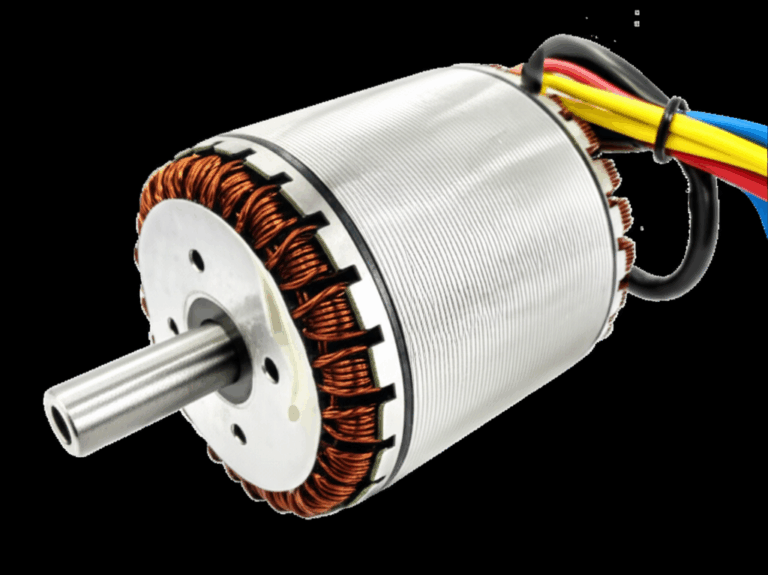
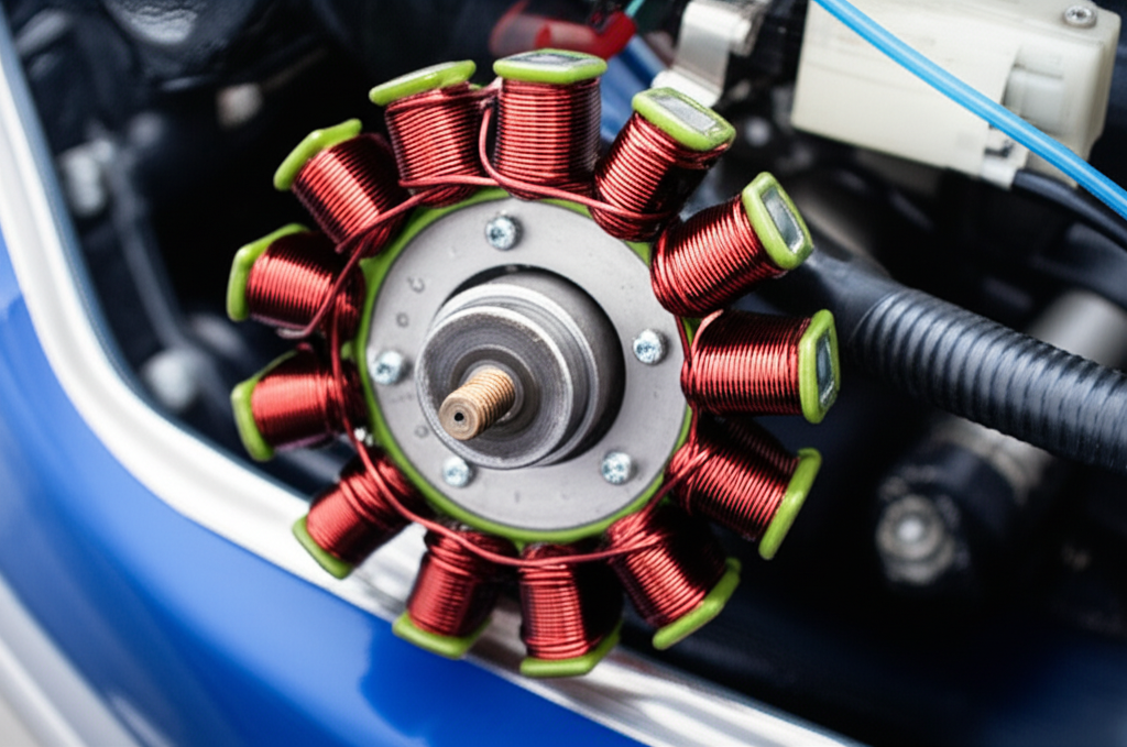
A stator in a personal watercraft (PWC) is a stationary annular assembly of laminated steel teeth and copper coils that sits under the flywheel. The flywheel carries permanent magnets and spins with the crankshaft. The stator does not move. It converts mechanical rotation into electrical power.
- Location: Under the flywheel on the front of the engine inside the engine compartment
- Components: Laminated steel core, charging coils, lighting coils on some models, and a pickup or pulse coil for ignition timing
- Output: Alternating current (AC) that feeds a rectifier/regulator which converts it to direct current (DC)
- Purpose: Charge the 12V battery and power the electrical system while the engine runs
- Systems it supports: Ignition system and spark plugs, fuel system on EFI units (fuel pump and injectors), lights, display/gauges, bilge pump, and accessory power
People also call this assembly a magneto. You will see terms like stator generator jet ski or magneto stator jet ski used interchangeably.
How a Jet Ski Stator Works: From Motion to Electricity
Think of the flywheel magnets as a spinning lighthouse and the stator teeth as shoreline piers. As the magnetic field sweeps past each tooth it pushes and pulls electrons in the copper windings. That motion induces AC voltage. This is electromagnetic induction.
- Engine rotation: The crankshaft turns the flywheel with embedded magnets
- Induction: The changing magnetic field cuts the stator windings which induces AC current
- AC output: The stator generates alternating current at a voltage proportional to RPM and winding design
- Rectifier/regulator: This unit converts AC to stable DC and regulates voltage to safe levels
- Battery charging: The DC output tops off and maintains the 12V battery
- System power: The DC bus feeds ignition, ECU, sensors, lights, and accessories
On many PWCs the stator also includes a pulse coil or timing pickup coil. That small sensor sees the passing flywheel trigger and provides a clean timing signal for ignition. Some models use a crankshaft position sensor instead. Any failure in these coils can cause engine misfires or no‑start conditions.
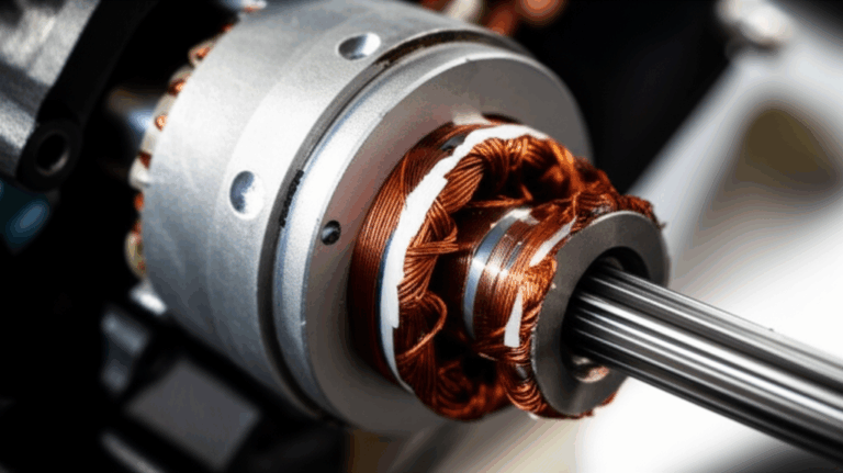
Inside the Stator: Laminations, Coils, and Materials
The stator’s heart is the laminated core. It is a stack of thin electrical steel sheets insulated from one another. This design cuts eddy current losses and keeps heat in check. Here is why it matters.
- Eddy currents: Changing magnetic fields generate unwanted currents in the core that turn into heat
- Hysteresis: Magnetic domains flip as the field reverses which consumes energy
- Laminations: Thin insulated sheets break up the eddy currents which lowers loss and temperature
- Material: Non‑oriented silicon electrical steel balances cost and performance across RPM and load
Analogy time. Picture water in a river. Eddy currents are like little whirlpools that waste energy. Laminations act like baffles that chop big whirlpools into harmless ripples. You still get flow without the drag.
For engineers and buyers the lamination choice drives performance and cost.
- Thickness: Thinner laminations lower eddy current loss at high frequency or high RPM yet cost more to make
- Grade: Silicon content and grain orientation affect magnetic permeability and core loss
- Coating: Organic or inorganic insulation coatings prevent interlaminar shorts and resist corrosion in marine environments
- Stack build: Interlocking, bonding, or welding methods influence rigidity, magnetic properties, and cost
If you are evaluating stator cores or looking to upgrade material selection you can dig deeper into the role of electrical steel laminations. For jet ski magneto stators you will typically use non‑oriented silicon steel with robust insulation to handle heat and moisture.
Diagnosing a Bad Stator: Tests and Measurements
You can test a stator with a basic multimeter and the service manual spec. Always disconnect the battery safety lanyard and follow your model’s procedures. Use eye protection. Saltwater and electricity do not show mercy.
Tools you need:
- Multimeter with AC voltage and ohms
- Jet ski service manual stator section for your exact model
- Back‑probe leads
- Dielectric grease and contact cleaner
- Basic hand tools to access connectors and the flywheel cover
Key tests:
1) Voltage output test
- Unplug the stator leads from the rectifier/regulator
- Start the engine if possible and measure AC voltage across the stator phases at idle and at a specified RPM
- Compare to published stator voltage output jet ski specs in the manual
- Low AC output indicates weak charging coils or a shorted winding
2) Resistance and continuity test
- With the engine off disconnect the stator
- Measure resistance in ohms between each stator coil lead pair
- Look for open circuit stator conditions or readings far off the service spec
- Check for continuity to ground which would reveal a short circuit stator to the core
3) Grounding and insulation test
- Verify no coil lead shows continuity to engine ground
- Inspect the wiring harness jet ski side for chafing and pinched wires near the engine mount
- Confirm solid grounding at the rectifier/regulator and battery negative cable jet ski connection
4) Ruling out other components
- Verify battery health with a load test and a jet ski battery health check
- Check the rectifier/regulator function and look for overheating rectifier/regulator symptoms
- Inspect the fuse box and terminal connections for corrosion and voltage drop jet ski issues
Many “dead battery jet ski” complaints point to a bad rectifier/regulator rather than the stator. You must test both before buying parts.
Symptoms You’ll See on the Water
A failing stator telegraphs several classic signs:
- Dead or draining battery after rides despite using a battery tender
- Difficulty starting or weak cranking because the battery never charges fully
- Flickering or dim lights/gauges at idle and low RPM
- Engine misfires or poor performance due to unstable ignition power or timing signal
- Overheating rectifier/regulator because a failing stator stresses the unit
- Battery warning light or check engine light if equipped
- Loss of accessory power including the bilge pump or display
Consequence of a bad stator jet ski owners ignore too long. You will walk the ski to shore.
Why Stators Fail in PWCs
Failures usually come from heat, contamination, or electrical stress. The marine environment is punishing.
- Overheating: High RPM and poor cooling drive insulation breakdown and stator overheat jet ski complaints
- Water intrusion: A compromised gasket or seal allows moisture that corrodes windings and shorts turns
- Saltwater: Salt accelerates corrosion which attacks terminal connections and any unprotected steel or copper
- Vibration: Loose fasteners or a rubbing flywheel cause physical damage
- Regulator faults: A failing rectifier/regulator can cook the stator with uncontrolled current and voltage
- Poor grounding: High resistance grounds increase heat and create voltage spikes
- Aging: Insulation hardens and cracks over time which leads to shorts or open circuits
If you see jet ski terminal corrosion, green powder on connectors, or white salt deposits, you found trouble. Use waterproof connectors jet ski grade and dielectric grease to fight it.
Repair, Replacement, and Cost Guide
Is it a DIY job? It can be with moderate mechanical skill. You need a flywheel puller, torque wrench, and patience. You also need to route the wiring correctly and seal everything to prevent water intrusion.
Pros of DIY:
- Save labor cost
- Immediate control over part choice OEM stator jet ski vs aftermarket stator jet ski
- You learn your machine which pays dividends later
Cons of DIY:
- You may need special tools and a service manual
- The job can take time in tight engine compartments
- Mistakes can cause expensive damage
Cost considerations:
- Parts: Aftermarket stator units often range from $80 to $250 which depends on brand and model
- OEM: Many run $200 to $600 or more on Sea‑Doo, Yamaha WaveRunner, Kawasaki Jet Ski, and Honda AquaTrax
- Labor: A jet ski repair shop charges 2 to 5 hours which lands near $200 to $600 at common shop rates
- Total repair cost often sits between $300 and $1,200 for parts plus labor
Stator winding repair jet ski rewinds exist yet are less common for PWCs due to labor cost and small size. Most shops replace as a unit. Always replace a suspect rectifier/regulator at the same time if tests show issues. That protects the new stator.
Material and Manufacturing Choices That Affect Stator Performance
If you design or source stators and motor core laminations, you have a few levers you can pull. Each choice impacts loss, heat, footprint, and cost. The marine duty cycle and limited cooling make these decisions more critical than they look on a drawing.
Material considerations:
- Non‑oriented silicon steels (CRNGO): Good all‑around performance across RPM with competitive cost which suits most PWC charging coils
- Higher‑silicon grades: Lower core losses at frequency with trade‑offs in punchability and brittleness
- Cobalt alloys: Superior saturation and loss at high frequency which carry a significant cost premium and are overkill for most magneto stators
- Insulation coatings: Choose high‑temperature inorganic or hybrid coatings that resist moisture and salt creep
- Thickness: 0.35 mm to 0.50 mm laminations are common for low frequency magnetos. High RPM or multi‑pole designs can justify thinner sheets
Manufacturing and assembly processes:
- Stamping vs laser cutting:
- Stamping offers high volume throughput with consistent edge quality and lower part cost
- Laser cutting shines for prototypes and complex shapes with no tooling yet adds heat‑affected zones that raise local core loss
- Stack assembly:
- Interlocking laminations create rigid stacks without welding which avoids heat that can degrade magnetic properties
- Bonding with resin or adhesive delivers excellent stack integrity and low vibration which may add process steps and cure time
- Welding or staking is robust and cost‑effective which can introduce local distortion and loss
- Annealing and stress relief: Proper post‑processing can recover magnetic properties after stamping or laser cutting
- QA and testing: Verify core loss per IEC 60404 methods and track B‑H curves to ensure permeability and coercivity meet targets. Confirm coating class, pinhole counts, and stack factor
If you want a deeper dive on stator cores and stacking methods review the overview on motor core laminations and the specific pages on stator core lamination. For high‑speed permanent magnet alternators the design space overlaps with BLDC machines. You can reference a bldc stator core approach for slot geometry and winding fill strategies.
Standards and specs that help align teams:
- ASTM A677 covers non‑oriented electrical steel sheet and strip
- IEC 60404 series defines magnetic property measurement methods
- ISO 2768 brings general tolerances for stamping and assembly
- OEM‑specific insulation and corrosion resistance requirements for marine use
Which Option Fits Your Use Case
Match the material and process to the job your stator must do.
- High RPM, small diameter flywheel:
- Consider thinner laminations with a tougher insulation coating
- Target low core loss at the expected electrical frequency which equals pole count times mechanical speed
- EFI models with high accessory loads:
- Ensure higher copper fill and adequate wire gauge
- Verify rectifier/regulator current rating with a margin for lights, gauges, display, and the bilge pump
- Saltwater use:
- Favor coatings and potting methods that seal windings and terminations
- Use stainless hardware and wrinkle‑free gaskets and seals
- Limited airflow and tight engine compartment:
- Prioritize low loss steels and high thermal class insulation
- Provide heat sinking for the rectifier/regulator
- Low volume prototype or retrofit:
- Use laser cut laminations to iterate quickly
- Switch to stamping once design freezes for cost and throughput
Be honest about trade‑offs. Laser cutting offers speed and flexibility which raises part cost and can increase local losses if not annealed. Interlocking laminations avoid weld heat which requires tight control of stack height and flatness. There is no magic bullet. You balance performance, durability, and price.
Procurement Checklist for Stator Cores and Assemblies
A tight RFQ avoids rework and surprises. Here is a practical checklist you can use with suppliers or internal teams.
Define the electrical target:
- AC output voltage at idle and at rated RPM
- Expected load profile for charging coils, lighting coils, and accessory power
- Temperature rise limits and duty cycle
Specify the core:
- Lamination material grade with allowable substitutes
- Lamination thickness and insulation coating class
- Stack height, outer and inner diameters, slot count and geometry
- Stack factor requirement and permissible burr height
Call out manufacturing:
- Stamping vs laser cutting
- Annealing requirements
- Assembly method: interlock, bonding, or weld
- Potting or varnish impregnation method if used
Validation and QA:
- Core loss test method and acceptance limits
- B‑H curve data at relevant flux densities
- Electrical safety tests: hipot and insulation resistance
- Salt fog or corrosion test if applicable for marine environment
Terminations and harness:
- Wire gauge, insulation type, and temperature class
- Connector family with waterproof rating
- Grounding provisions and strain relief
- Markings that match the jet ski electrical schematic
Ask for samples and PPAP‑style documentation for serial production. If you need a broader context on materials and supply families a walkthrough of electrical steel laminations helps frame choices across programs.
Brand‑Specific Notes: Sea‑Doo, Yamaha WaveRunner, Kawasaki, Honda
Each OEM takes a slightly different path. A few quick notes can save time.
- Sea‑Doo stator issues:
- Many models pack electronics tightly which increases heat
- Check for water intrusion near the front cover gasket
- Yamaha WaveRunner stator problems:
- Robust charging systems yet age‑related insulation breakdown shows up around 7 to 10 years
- Inspect the rectifier/regulator early when diagnosing a jet ski charging system
- Kawasaki Jet Ski stator repair:
- Flywheel removal can be stubborn. Use the correct puller
- Verify the pulse coil air gap and timing after reassembly
- Honda AquaTrax stator function:
- EFI loads are higher. Battery health matters more
- Follow the service schedule and watch for connector corrosion
Older Polaris models exist in the used market. Parts vary widely. Always reference the correct jet ski electrical system diagram and service manual.
Preventive Maintenance and Storage Tips
You can extend stator life with a few simple habits.
- Battery care:
- Use a jet ski battery tender during storage
- Load‑test the battery at the start of the season which reduces stress on the charging system
- Clean electrical connections:
- Remove and clean the positive cable jet ski and negative cable jet ski ends
- Inspect the ground wire jet ski connection to the engine block
- Apply dielectric grease and seal boots to cut corrosion
- Winterization and storage:
- Fog the engine per the manual
- Keep the PWC dry and ventilated which prevents condensation and salt creep
- Follow jet ski storage electrical tips for disconnecting or maintaining the battery
- Cooling considerations:
- Make sure the engine cooling system works which keeps overall temperatures down around the stator
- Check that the rectifier/regulator has proper airflow or a clean heat sink
- Periodic checks:
- Do a quick multimeter use jet ski check at idle. Confirm the battery sees charging voltage per the manual
- Scan for wiring harness abrasion and replace compromised waterproof connectors
Preventative maintenance jet ski stator care is not glamorous. It saves you hours lost on the water.
Jet Ski Stator Data and Common Issues Summary
The public market lacks formal fleet‑wide statistics. Common observations from service networks and parts suppliers point to consistent patterns. Use these ranges as directional guidance. Always confirm with your model’s documentation.
| Metric / Category | Description | Common Observations / Data Points |
|---|---|---|
| Primary Function | Electrical power generation for battery charging and system operation | Converts mechanical energy into AC electricity then rectified to DC. Crucial for ignition, fuel, lights, and gauges |
| Common Failure Modes | Overheating, insulation breakdown, short circuits, open circuits, physical damage | Overheating from sustained high RPM or a failing rectifier/regulator. Insulation breakdown causes shorts between windings or to ground. Open circuits from broken wire windings. Physical damage from flywheel or debris |
| Typical Lifespan | Highly variable 5–15+ years or 100–500+ hours | Average near 7–10 years or 200–300 hours for many models when used in mixed conditions. Saltwater shortens life if not rinsed and maintained |
| Estimated Failure Rate | Moderate to high for older or neglected units | Newer PWC under 5% failure. Mid‑life PWC 10–20% likelihood. Older PWC 25–50% with the rectifier/regulator often implicated |
| Average Parts Cost (USD) | Stator unit itself | Aftermarket $80–$250. OEM $200–$600+ depending on model |
| Average Labor Cost (USD) | Professional installation at a marine shop | 2–5 hours of labor $200–$600 given $100–$150 per hour typical rates |
| Diagnostic Time | Time to identify a faulty stator | 0.5–1.5 hours with a multimeter including rectifier/regulator tests |
| Impact of Saltwater | Accelerated corrosion and degradation | Saltwater exposure corrodes electrical connections and promotes insulation failure which shortens life |
| Associated Failures | Often fails together with the rectifier/regulator | A failing stator stresses the regulator and vice versa which causes cascaded failures |
| Preventive Measures | Battery checks, clean connections, proper winterization | A healthy battery and clean grounds reduce charging load. Confirm cooling and keep connectors sealed |
Stator vs Alternator on a Jet Ski
People ask if a jet ski has an alternator. It does in principle. The magneto stator and flywheel act as a permanent magnet alternator. The stator generates AC power which a rectifier/regulator converts to DC. PWCs use a compact radial design under the flywheel rather than a belt‑driven automotive alternator.
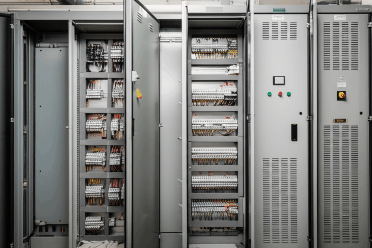
Wiring, Schematics, and Upgrades
When troubleshooting, lean on the jet ski electrical schematic. Trace the charging system diagram PWC connections from stator to rectifier/regulator to battery. Check the wiring harness, fuse box, and grounding points. Watch for voltage drop jet ski symptoms caused by corrosion or loose terminals.
If you add accessory power loads like upgraded lights or sound systems, consider a jet ski charging system upgrade. Confirm the rectifier/regulator capacity. Upsizing the battery helps with surge loads yet does not fix an undersized charging system.
The Business Case: Why Laminations and Process Control Matter
Engineers and procurement teams win when end users stop noticing their charging systems. That takes materials with the right magnetic properties, consistent stack construction, and robust sealing. A few production realities to keep on your radar:
- Tooling condition affects burr height and edge damage which raises core loss
- Inconsistent insulation coatings lead to interlaminar shorts and hot spots
- Variability in stack factor skews magnetic performance and temperature rise
- Poor potting or varnish leaves capillary paths for salt water
- Supplier QA around IEC 60404 and ASTM A677 data reduces field variability
If you design e‑pumps, BLDC drives, or move into full electric PWCs you will also care about rotor design. Stator lessons carry over. For permanent magnet machines both stator and rotor lamination choices drive efficiency and heat. You can explore BLDC stator geometry via a bldc stator core reference and keep your stack‑up aligned with your loss targets.
Frequently Asked Diagnostics Questions
- How to diagnose bad jet ski stator quickly
- Measure AC output at the stator leads. If low across all phases suspect the stator. If AC looks good check the rectifier/regulator
- What does the pulse coil jet ski do
- It provides a timing reference for ignition. If it fails you can get misfires or no spark
- Can a stator cause jet ski performance issues electrical
- Yes. Low voltage starves the ECU and fuel pump on EFI models which causes bogging or stalling
- Can I repair a short circuit stator winding
- Most marine shops replace the unit. Rewinding is possible yet often not economical
- How often do stators fail jet ski
- Age, heat, and salt drive failures. Many last the life of the ski with good maintenance
Your Engineering Takeaway
If you remember nothing else remember this. The stator is the unseen powerhouse in your jet ski. It generates AC power from engine rotation. The rectifier/regulator turns that into DC to charge the battery and run everything from spark plugs to gauges. Laminations and materials inside the stator core determine how cool and efficient it runs in a tight, salty, hot environment.
Key points:
- A stator sits under the flywheel and creates AC power through electromagnetic induction
- The rectifier/regulator converts AC to DC and caps voltage to protect electronics
- Most charging complaints come from either the stator or the regulator so you must test both
- Laminations matter. Thinner, well‑coated sheets cut eddy currents and heat which boosts life
- Material and process choices like silicon steel grade, insulation coatings, and stack assembly drive performance and cost
- Maintenance prevents headaches. Keep grounds clean and batteries healthy and connectors sealed
Next steps you can take today:
- If you are troubleshooting use a multimeter and the service manual to run AC output, resistance, and ground tests
- If you are specifying parts define lamination grade, thickness, coating, and assembly method up front and ask for IEC 60404 test data
- If you are purchasing request a structured RFQ package with electrical targets, stack specs, coating details, and QA criteria
- If you want a quick refresher on core options scan these resources on motor core laminations and stator core lamination
A healthy stator means reliable starts, steady gauges, and more grins on the water. Address symptoms early. Choose materials wisely. Build with care. Then go ride.