What Does a Stator Do in a Motor? The Stationary Heart of Motion
Every motor you specify or build depends on one quiet hero. The stator. It sits still by design. Yet it creates the magnetic field that makes everything spin. In one line. The stator converts electrical input into a controlled magnetic field that interacts with the rotor to produce torque and rotation. That simple idea powers conveyor lines, pumps, CNC machines, EVs, fans, and wind turbines.
Why should you care? Because stator design and quality drive motor efficiency, power density, thermal behavior, reliability, and cost. When the stator’s magnetic circuit and windings perform well, your machine runs cooler and lasts longer. When they don’t, you fight overheating, vibration, and downtime. This guide gives you the engineering fundamentals and the practical choices you need to get it right.
In other words. We will explain the physics in plain English, size up your options for materials and manufacturing, and hand you a short list of next steps so you can design or buy with confidence.
In This Article
- The Stator’s Core Function: Creating a Stationary Magnetic Field
- Anatomy of a Stator: Core, Windings, Insulation
- How a Stator Works: Step by Step
- Stator Variations by Motor Type: AC, DC, BLDC, Synchronous
- Why the Stator Matters for Efficiency, Power, and Reliability
- Common Stator Failures and Maintenance Practices
- Materials and Manufacturing: What to Choose and Why
- Application Fit: Matching Design Choices to Use Cases
- FAQs About Stators
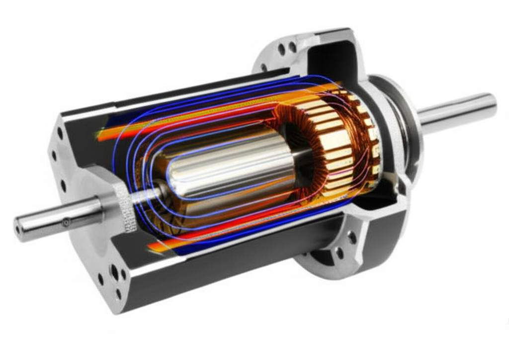
The Stator’s Core Function: Creating a Stationary Magnetic Field
At its core, the stator is the stationary part of an electric motor. It houses the magnetic circuit and the windings. When you feed the windings with electrical current, they create magnetic poles in a controlled pattern. That magnetic field is “stationary” relative to the motor frame. In AC machines the field distribution is fixed to the stator but the pole pattern rotates around the bore. Engineers call that a rotating magnetic field. In DC machines the field can be steady or electronically commutated.
The stator’s magnetic field interacts with the rotor’s field or with rotor currents induced by electromagnetic induction. That interaction produces torque. No stator field means no rotor torque. No torque means no motion.
Two fundamental laws sit behind this:
- Faraday’s Law of Induction: A changing magnetic field induces voltage in a conductor.
- Lorentz Force: A current-carrying conductor inside a magnetic field experiences a force. That force, arranged around the motor’s circumference, becomes torque.
You design the stator so those effects work for you. You pick the core material and lamination thickness to minimize losses. You choose the number of poles and slot geometry to shape the magnetic field. You match winding configuration and phase count to the drive electronics and the application.
Anatomy of a Stator: Key Components
Think of the stator as a magnetic circuit plus copper conductors plus protection against heat and voltage stress. Each piece matters.
Stator Core
The stator core is a stack of thin electrical steel sheets called laminations. Engineers use laminations because solid steel would let eddy currents whirl inside the core like unwanted whirlpools. Those currents turn precious electrical energy into heat. Thin, insulated sheets break the paths for these eddies which reduces loss.
- Laminated steel construction: Most stator cores use silicon steel or other electrical steels with high magnetic permeability. Permeability is how easily magnetic flux passes through a material. Like how a sponge soaks up water.
- Flux guidance: The teeth and yoke geometry guide magnetic flux from slot to slot and around the circumference. Good geometry boosts torque density and trims flux leakage.
If you want to see how stator cores are stacked and insulated in practice, review a typical stator core lamination reference. You will see slot shapes, tooth tips, and the thin interlaminar insulation that fights eddy currents.
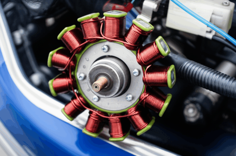
Stator Windings and Coils
Copper windings sit in the stator slots. Copper wins because it offers high conductivity and good thermal properties. The windings form phase coils that create magnetic poles when energized.
- Phase windings: Single-phase motors use split-phase or capacitor-start arrangements. Three-phase motors use three sets of coils displaced by 120 electrical degrees. The result is a rotating magnetic field for induction and synchronous machines.
- Winding patterns: The choice between distributed windings and concentrated windings affects harmonics, torque ripple, and manufacturability. BLDC and some PMSM designs often use concentrated windings to shorten end turns and boost copper fill.
Insulation System
Insulation isolates turns from turns and coils from the core. It prevents short circuits and keeps the motor alive in a harsh electrical and thermal environment.
- Film and slot liners: Polyester films, aramid papers, and glass-mica composites line the slots and wrap coils.
- Thermal classes: Class F and H insulation handle higher temperatures which extends life under thermal stress. A widely used rule of thumb says every 10 degrees Celsius of continuous temperature rise halves insulation life.
- Dielectric strength: You choose materials and impregnation methods to hit the needed dielectric strength and partial discharge resistance at your operating voltage and switching speeds.
How a Stator Works: A Step-by-Step Breakdown
You can break the stator’s job into four simple steps.
1) Electrical Power Input
You supply AC or DC power to the stator windings. In AC induction and synchronous machines the input is AC at a certain frequency. In BLDC and stepper motors the drive electronics shape DC into controlled waveforms.
2) Magnetic Field Generation
Current through the coils creates magnetic poles in the stator teeth. The pattern depends on the number of poles and the phase currents. In three-phase machines those currents create a rotating magnetic field whose synchronous speed equals 120 times frequency divided by the number of poles. If you double frequency you double synchronous speed.
3) Interaction with the Rotor
- In induction motors the stator field cuts the rotor bars which induces currents in them. Those currents create their own magnetic field which interacts with the stator’s rotating field and produces torque. The rotor runs slightly slower than synchronous speed. That speed difference is slip which is required for induction.
- In synchronous motors the rotor field locks to the stator’s rotating field. The rotor includes permanent magnets or DC-excited windings. Once locked it spins exactly at synchronous speed.
- In DC and BLDC machines the stator field interacts directly with the rotor’s magnets or with commutated currents.
4) Producing Torque and Rotation
The magnetic fields push and pull on each other around the air gap. That tangential force creates torque which spins the rotor. The shaft converts it to mechanical output. You control torque by controlling current. You control speed by adjusting frequency and applied voltage.
Stator Variations Across Different Motor Types
Different motor families put the stator to work in slightly different ways. The core idea stays the same. The execution changes.
AC Induction Motors
The stator creates a rotating magnetic field. The rotor is a squirrel-cage or wound rotor in which currents are induced. The stator sets starting torque, efficiency, and power factor through slot geometry, number of poles, and core material. Three-phase induction motors deliver robust, low-maintenance operation which is why you see them in pumps, fans, and compressors.
Synchronous Motors
The stator field rotates just like in an induction motor. The rotor carries permanent magnets or a DC-excited field winding. The rotor locks to the stator field. Synchronous motors offer high efficiency and precise speed control which makes them a fit for servo drives, robotics, and high-efficiency industrial drives.
Brushless DC Motors (BLDC)
In BLDC motors the stator carries the windings. The rotor holds permanent magnets. Electronic commutation switches the stator currents to create a rotating field that pulls the rotor around. BLDC designs give you high torque density and fast response. If you build or specify BLDC machines, look at what defines a quality bldc stator core. You will see concentrated windings, skew strategies to reduce cogging, and attention to end-turn length.
DC Motors
Traditional brushed DC motors often put the permanent magnets on the stator and wind the armature on the rotor. The commutator and brushes manage current switching. The stator’s job is simpler here. It sets a steady magnetic field that the rotor windings can push against.
Stepper Motors
Steppers use a stator with multiple tooth phases and a toothed rotor that moves in precise steps. The stator energizes phases in sequence. The magnetic alignment steps the rotor forward by a fixed angle each time. Great for CNC positioning and 3D printers.
Generator Stators
Flip the energy flow and you get generators. The stator in a generator develops output voltage and current as the rotor’s field sweeps by. Wind turbine and hydro generators depend on robust stator design for efficiency and uptime.
Why the Stator Matters for Efficiency, Power, and Reliability
Stator choices ripple into everything that matters to your program. Efficiency, power, thermal headroom, reliability and cost.
- Efficiency and losses: Stator core losses include hysteresis and eddy current losses. Hysteresis loss comes from flipping magnetic domains every cycle. Eddy current loss comes from induced circulating currents in the core. Thinner laminations and better steel grades cut both.
- Power and torque: Stronger stator fields create more torque which unlocks higher power density. You manage field strength with slot fill, copper cross section, and core material with high permeability.
- Thermal management: Lower losses drop winding and core temperatures. Designs that move heat effectively run cooler which extends insulation life and bearing life. Cooling systems like forced air and liquid jackets help when you push power density.
- Reliability and life: About 30 to 40 percent of motor electrical failures start in stator windings. Insulation breakdown and thermal degradation lead the list. Good materials and stress control push that risk down.
- Control and dynamics: The stator’s fixed coils give you precise control of magnetic fields. That means fast torque changes for robotics and EV traction and clean speed regulation for CNC spindles.
A few numbers that help anchor decisions:
- Many standard industrial motors last 15 to 20 years under normal operation. Each continuous 10 degree Celsius rise can cut insulation life roughly in half. That rule of thumb aligns with NEMA and IEEE guidance on thermal aging.
- Efficient stator and winding design is one reason modern motors hit IE4 to IE5 efficiency. Every single point of efficiency often saves 1 to 2 percent of lifetime energy.
- When you reduce operating temperature by 10 degrees Celsius you can double insulation life. Better cooling and lower core loss get you there.
- Predictive maintenance using temperature, vibration, and current signature analytics can spot stator issues early. Practitioners report large reductions in unplanned downtime and maintenance cost when they deploy it well.
Common Stator Failures and Essential Maintenance
If a motor quits or runs hot, check the stator first. It is the usual suspect for many electrical faults.
- Winding failures: Turn-to-turn shorts, phase-to-phase shorts, and open circuits. Often triggered by thermal stress, voltage spikes from drives, or contamination.
- Insulation breakdown: Heat, age, and partial discharge chew away at insulation. High dv/dt from VFDs stresses turn insulation which can accelerate aging.
- Overheating: High ambient temperature, blocked ventilation, high harmonic currents, or overload can push temperatures beyond class limits.
- Vibration and mechanical stress: Looseness in the core stack or end-winding movement leads to abrasion and eventual electrical failure.
Diagnostic tools and practices:
- Insulation resistance and polarization index tests. Good for trending condition over time.
- Surge and hipot tests. Useful for detecting turn short risk and dielectric integrity.
- Motor current signature analysis. It can reveal broken rotor bars and eccentricity which interact with stator loading.
- Infrared thermography and embedded RTDs or thermistors in the windings. Real-time protection beats post-mortems.
- Vibration analysis. Misalignment and rotor eccentricity can increase stator tooth stress and noise.
Preventive steps:
- Stay within the motor’s thermal class. Upgrade to Class F or H insulation if your duty cycles demand it.
- Use dv/dt filters or sine filters with VFDs for long cable runs and high switching frequencies.
- Keep the air gap clean. Dust and conductive debris raise risk and trap heat.
- Balance phases and keep power factor in line. Poor power factor and imbalance increase I2R losses in windings.
Materials and Manufacturing: What to Choose and Why
Here is where design meets the factory. Materials and processes determine performance, repeatability, and cost.
Material Considerations
- Electrical steels (silicon steel laminations): These are the workhorse materials for stator cores. They offer high permeability and low loss. Higher silicon content reduces core loss. Thinner gauges reduce eddy currents. Look up common M-grades and their loss curves. If you want a primer, start with a practical overview of electrical steel laminations.
- Cobalt alloys: Excellent for high-frequency and high-temperature applications. They offer high saturation flux density which lifts power density. The tradeoff is cost and machinability.
- Amorphous and nanocrystalline alloys: Ultra low core loss at high frequencies. Often used in transformers and specialized high-speed motors. They can be brittle which complicates stamping and stacking.
- Permanent magnets: Not part of the stator in induction machines, yet central in BLDC and PMSM motors where the stator must be designed to manage strong rotor magnet fields without saturation. Material choices for magnets include NdFeB and SmCo with different temperature and demagnetization characteristics.
Manufacturing and Assembly Processes
The stator core is a lamination stack. You can create it in several ways which change cost and performance.
- Stamping: Best choice for high-volume production with consistent features and low per-piece cost. Tooling is an up-front investment. Stamping preserves magnetic properties when dies are sharp and the process is tuned.
- Laser cutting: Ideal for prototyping and low volumes or complex geometries with small changes between iterations. Thermal effects from cutting can increase loss, yet you can control it with process parameters and post-processing.
- Waterjet and wire EDM: Useful for specialized materials or when you need burr-free edges. Slower than stamping for production volumes.
- Stacking methods: Interlocking tabs, welding, bonding, or rivets hold laminations together. Interlocks work like LEGO bricks which avoids heat-affected zones that can raise losses. Bonding with insulating adhesives improves rigidity and reduces vibration noise.
- Annealing: Post-cut annealing can restore magnetic properties that were damaged by cutting stress which lowers core loss.
- Insulation coatings: Each lamination carries a thin inorganic or organic insulation. It breaks eddy current paths. Coating class and thickness matter for loss and thermal conduction.
If you want to compare finished assemblies and the tradeoffs between geometries, scan a catalog of motor core laminations. You will see how slot shapes and stack heights change with application.
Windings and Impregnation
- Copper wire: Round or rectangular. Rectangular conductors can increase slot fill and reduce resistance which helps efficiency.
- Winding methods: Needle winding and hairpin winding increase consistency and fill factor. Hairpin coils offer repeatability and high copper density. They introduce higher local eddy currents at high switching frequencies which calls for careful design.
- Impregnation: VPI (vacuum pressure impregnation) fills voids which improves heat transfer and mechanical stability. Resin systems must match temperature and voltage stress.
Slot and Air Gap Design
- Slot geometry: Tooth width, slot opening, and wedge decisions influence the magnetic circuit and the harmonic content. That spills into torque ripple, acoustic noise, and efficiency.
- Air gap: Small gaps increase magnetic coupling which increases torque density. Tolerances here drive both performance and manufacturability. Rotor eccentricity can increase loss and noise.
Rotor-Stator Pairing
You design stator and rotor together. Slot numbers, skew strategies, and magnet placement must complement each other. For a side-by-side comparison of rotor construction choices, including bar shapes and magnet topologies, browse a typical rotor core lamination overview. You will see how rotor decisions change stator demands.
Application Fit: Matching Design Choices to Use Cases
You rarely design in a vacuum. The application pushes you toward the right stator materials and processes.
- Industrial pumps and fans: AC induction motors with robust stator cores in silicon steel. Focus on efficiency, low noise, and long life. Three-phase stators with IE3 to IE4 targets are common. NEMA and IEC frame standards simplify procurement and interchangeability.
- Electric vehicles: Permanent magnet synchronous motors and interior permanent magnet designs dominate. Stator cores must handle high torque density and frequent transients. Hairpin windings and liquid cooling increase copper fill and heat removal. OEMs like Tesla and suppliers across the EV ecosystem pair high-grade steels with advanced slot geometries.
- Robotics and CNC: Synchronous servo motors with precise stator fields for torque linearity and quick response. Low cogging and smooth control matter more than raw power.
- Household appliances: Cost matters. Single-phase induction or BLDC motors with optimized stator designs reduce energy use and noise. BLDC wins where power savings justify the electronics.
- Wind turbines and generators: Large stators with careful cooling and insulation systems. Thermal cycling and vibration demand strong stacking and impregnation methods.
- High-speed spindles: Thin laminations and high-grade steels reduce core loss at high frequency. You trade thickness for loss and manufacturability.
As you map these choices, remember the wire-to-iron balance. Boosting copper reduces I2R losses which helps efficiency. Improving the iron path reduces core loss which lowers heat. You need both.
Control and Power Electronics: What the Stator Sees
Variable frequency drives (VFDs) and inverter controls change what the stator experiences.
- Frequency and motor speed: Synchronous speed scales with frequency. VFDs let you dial in speed for process control or energy savings.
- Voltage and current: High switching speeds can create steep dv/dt which stresses insulation. Select insulation systems and filters that match your drive.
- Power factor: In induction machines, stator design and drives can improve power factor which reduces line current and heat.
- Sensor integration: RTDs, thermistors, and Hall sensors embedded in the stator offer protection and open the door to predictive maintenance. Smart motor technology and cloud analytics convert these signals into actionable maintenance.
Manufacturing Economics: Cost, Rewind, Repair
Cost is not a dirty word. It is a constraint that good engineering uses as a design input.
- Stator share of motor cost: Depending on size and technology, the stator can account for roughly 20 to 40 percent of motor manufacturing cost.
- Rewinding vs. replacement: Rewinding a stator often costs 30 to 50 percent of a new motor. That makes repair attractive for large or specialized machines.
- Early fault detection: Predictive approaches that catch stator faults early slash unplanned downtime and protect the rest of the machine. Many plants report 50 to 70 percent downtime reduction once analytics mature.
If your work touches transformer power as well, you will notice parallel decisions in core materials and laminations. The physics of eddy current and hysteresis losses do not care whether you are in a motor or a transformer.
Practical Design Tips: From Fundamentals to First-Pass Specs
Build your stator like a magnetics engineer who cares about manufacturability.
- Choose the right steel and thickness: Higher silicon content and thinner gauges reduce loss. At high frequency and with VFDs you get outsized benefits.
- Optimize slot fill without choking cooling: Copper density helps efficiency. Leave paths for resin and heat flow.
- Use skew and tooth shaping to reduce cogging: Small geometry changes pay off with lower torque ripple and quieter motors.
- Control tolerances where it counts: Air gap and stack straightness drive performance. Work with suppliers who show statistical process control on these features.
- Match insulation to the drive: Class F or H plus appropriate turn insulation and impregnation will survive high dv/dt and voltage spikes.
- Plan thermal paths: Forced air, liquid jackets, or integrated heat sinks keep temperatures in check which doubles life for every meaningful temperature drop.
A Quick Note on Standards and Testing
Rely on established standards and test methods when you compare designs or suppliers.
- NEMA and IEC motor standards define frames, efficiency classes, and test methods. Use them to compare apples to apples.
- IEEE test standards and IEC 60034 methods cover efficiency and loss separation which help you understand where watts disappear.
- Material standards for electrical steel define loss and permeability at specific test points. Use those curves when you select grades.
What About Cutting-Edge Approaches?
You have more tools than ever.
- Advanced bonding: Adhesive bonding of laminations creates rigid cores with low vibration and no weld loss penalties. Great for noise reduction and high-speed rotors.
- Additive manufacturing of stator cores: Researchers and pilot lines have reported lighter cores and reduced waste. Thermal paths can be improved which trims hotspot temperatures and increases efficiency a few percent in some cases. Feasibility depends on size and cost targets.
- Data-driven maintenance: Real-time temperature, vibration, and current signatures feed machine learning models. Plants that invest in sensors and analytics often predict failures with high accuracy which saves significant downtime.
When to Use Which Manufacturing Route
Laser cutting or stamping. Bonding or welding. The right answer depends on production volume, geometry, and performance priorities.
- Prototyping and low volume: Laser cutting gives you speed and flexibility which you need when designs will change. Post-cut stress relief helps keep losses low.
- High-volume programs: Stamping wins on cost and consistency. Invest in high-quality tooling and protect edge quality to keep core loss down.
- Assembly strength and noise: Interlocking and bonding control vibration and skew noise. Weld only when you must for structural reasons since the heat can degrade magnetic properties.
If you want to see how these methods map to finished parts, browse a supplier catalog of stator core lamination and motor core laminations. You will notice how the same principles carry across form factors.
Rotors and Stators: Always a Pair
You cannot optimize a stator in isolation. Rotor slot count and skew, magnet grade and geometry, and air gap choices tie directly to stator slot geometry and tooth shaping. Review rotor core lamination options alongside your stator plan. Matching the magnetic circuit on both sides reduces torque ripple, noise, and loss.
The Business Angle: Energy, Uptime, and Total Cost
Procurement managers and product owners want predictable cost and fewer surprises. The stator influences your business more than you might think.
- Energy costs: Motors consume significant electricity. A one percent efficiency gain often pays back quickly over service life.
- Uptime: Stator failures lead to long stops. Better insulation systems and early detection reduce that risk.
- Serviceability: Designs that allow clean rewinds and easy testing cut repair time. Clear documentation and conformance with IEC or NEMA standards ease replacement decisions.
FAQs About Stators
Q: Is a stator found in all types of motors?
A: Yes. Every electric motor has a stationary magnetic structure that we call the stator. In some DC machines the stator carries permanent magnets rather than coils. The function remains the same which is to provide the magnetic field.
Q: Can a motor run without a stator?
A: No. Without a stator field the rotor has nothing to push against so no torque is produced.
Q: What is the difference between a stator and a rotor?
A: The stator is stationary and creates or guides the magnetic field. The rotor turns inside that field and delivers mechanical output.
Q: How do I know if my stator is bad?
A: Watch for symptoms like overheating, tripping on ground fault, asymmetric phase currents, excessive vibration, or a burnt smell. Confirm with insulation resistance, surge testing, and thermal scans.
Q: What materials are stators made of?
A: Most use electrical steel laminations stacked into a core plus copper windings and insulation systems. High-performance designs may use cobalt alloy steels or amorphous materials for the core.
Q: How does the stator affect motor speed control?
A: The stator windings and the applied frequency set synchronous speed. With a VFD you change frequency to change speed. Stator design also affects dynamic response and torque ripple.
Q: Does lamination thickness really matter?
A: Yes. Thinner laminations reduce eddy current loss, especially at higher frequencies. They can raise cost or complicate manufacturing so you must balance performance and budget.
Q: What about BLDC stators?
A: BLDC stators use concentrated windings and carefully shaped teeth to reduce cogging and torque ripple. If you need a reference, here is what typical bldc stator core constructions look like.
Your Options Explained: A Practical Buyer’s Guide
Here is a quick side-by-side that engineers and procurement teams can use during sourcing.
- Silicon steels for general-purpose motors: Reliable, cost-effective, and well characterized. Good for induction motors, synchronous reluctance machines, and many PMSMs.
- Pros: Low loss at industrial frequencies, mature supply chain, fits NEMA and IEC expectations.
- Cons: Limited saturation levels compared to cobalt-based alloys. At very high frequency losses rise.
- Cobalt alloys for high-power density: Useful in aerospace and high-speed spindles where high flux density pays off.
- Pros: Higher saturation allows smaller machines for the same power.
- Cons: High cost and more difficult processing.
- Amorphous and nanocrystalline materials for high frequency: Excellent loss performance in transformers and some special motors.
- Pros: Very low core loss which is perfect for power electronics with high switching speeds.
- Cons: Brittle and challenging to stamp which can push you to laser or specialized processes.
- Winding choices: Round wire for flexibility and cost. Hairpin for high slot fill and repeatability. Pick based on duty cycle and frequency content from your drive.
When you examine materials and stacks in the market, a good catalog of electrical steel laminations will show insulation coatings, gauges, and typical loss data. Use that to narrow your short list.
“Which Application Is This For?” Picking the Best Fit
- High-volume industrial drives: Stamped laminations with interlocking or bonding. Distributed windings for smooth torque. Focus on IE3 to IE5 efficiency.
- Prototypes, custom geometries, or frequent design changes: Laser cutting and bonded stacks. Concentrated windings can shorten end turns and simplify assembly.
- EV traction: High-grade steels, tight air gaps, hairpin windings, and liquid cooling. Validate partial discharge behavior under fast-switching inverters.
- Robotics and precision motion: Skewed slots, carefully shaped teeth, and high-resolution feedback. Keep torque ripple low.
- Harsh thermal environments: Class H insulation, higher coercivity steels, and robust impregnation. Coercivity is the material’s resistance to demagnetization which matters near hot magnets and under fault conditions.
Honesty check. Laser cutting is fantastic for prototypes and low volumes since it gives you speed and design freedom. For large production runs of simple shapes, stamping usually delivers a lower cost per part and better consistency.
Engineering Takeaway: The Short List
- The stator converts electrical energy into a controlled magnetic field which drives torque through rotor interaction.
- Core material and lamination thickness dominate core loss and efficiency. Thinner sheets and better steel win at higher frequency.
- Winding configuration and copper fill set torque density and thermal behavior. Match insulation to your drive’s voltage and dv/dt.
- Cooling is not optional at high power density. Every 10 degrees Celsius reduction can double insulation life.
- Stators cause a large fraction of electrical motor failures. Predictive maintenance and robust insulation pay off.
- Design stator and rotor together. Slot counts, skew, and air gap must be a matched set.
If you are weighing options or want a second set of eyes on a design, bring a sample stack drawing and your duty cycle. We can review materials, slot geometry, and stacking choices against your targets for efficiency, torque ripple, and cost. Start with a quick scan of reference parts like stator core lamination, motor core laminations, and rotor core lamination to align on geometry and tolerances. Then refine to meet your application’s thermal and control needs.
You now have the fundamentals and the tradeoffs. Use them to ask sharper questions, to specify smarter, and to build motors that run cooler, last longer, and deliver the torque your application demands.