What Causes a Stator to Go Bad? Understanding Common Failures and Prevention
Every engineer who specs, buys, or services motors and alternators has faced the same headache: the stator fails sooner than expected. Output drops. Temperatures climb. The battery does not charge. The unit smells burnt. The team swaps parts yet the failure returns. If you are asking what causes a stator to go bad you are not alone. Stators sit at the heart of alternators, generators, and electric motors. When they go down they take your system with them.
This guide breaks the problem into plain engineering terms. We will explain the physics that drive stator failure, expose the usual suspects, and show you how design choices and manufacturing processes influence reliability and cost. Then we will give you a practical checklist that helps you diagnose issues fast and extend stator life with confidence.
In This Article
- Why stators fail in real machines
- The engineering fundamentals behind overheating, shorts, and open circuits
- Primary causes of stator failure you can verify
- Related components that accelerate stator damage
- Field symptoms and how to test a faulty stator
- Material and manufacturing choices that reduce risk
- Best-fit guidance for automotive, motorcycle, marine, and industrial applications
- Preventative measures to extend stator lifespan
- Quick reference table with causes, symptoms, and impact
- Engineering takeaways and next steps
Part 1: The Relatable Hook — The Problem You Are Solving
You need a stator that runs cool, delivers rated power, resists vibration, and holds up under real-life electrical abuse. Yet in the field you see alternator stator problems that look random. A motorcycle’s battery will not charge yet the regulator tests fine. A generator’s output sags then dies. A BLDC motor runs rough, overheats, and throws a burning smell. Procurement gets hit with rushed replacements and higher repair costs.
What is really going on? Most stator failures boil down to the same physics: heat and insulation stress. Add electrical faults, mechanical vibration, and environmental contamination. Mix in design compromises or manufacturing defects. The result is winding shorts, open circuits, or ground faults that take you offline. The good news is you can prevent a large share of these failures once you understand the root causes.
Part 2: What’s Really Going On? The Engineering Fundamentals
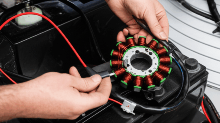
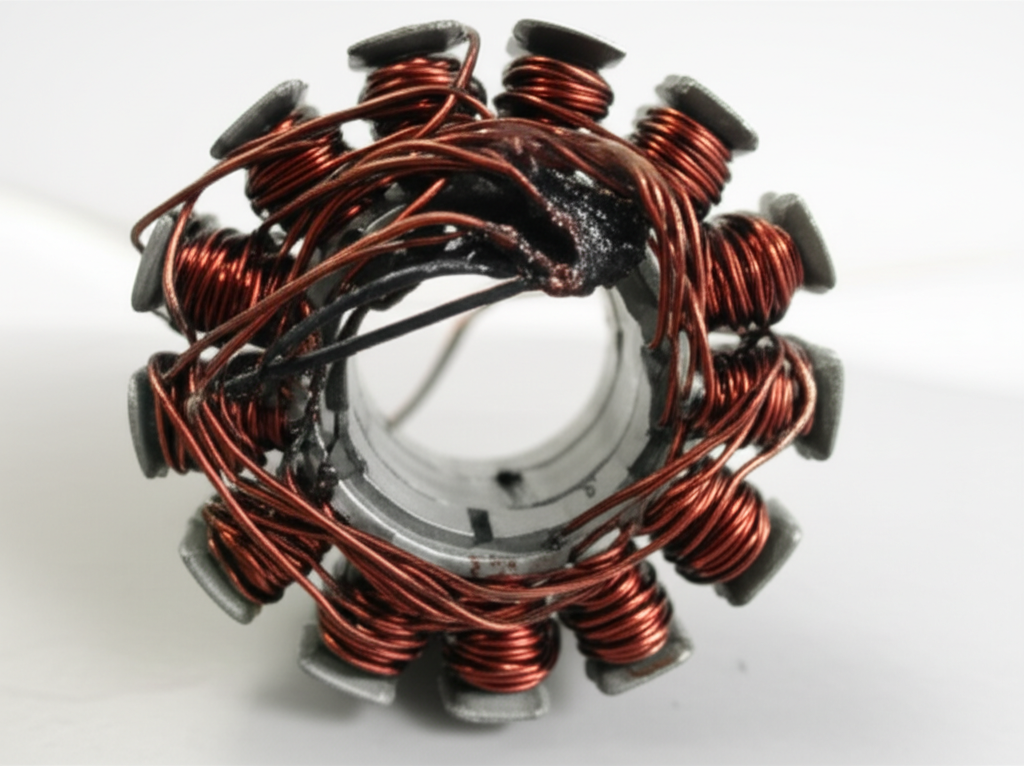
A stator is the stationary part of an alternator, generator, or electric motor. It contains laminated steel cores and copper wire windings. The rotor spins inside the stator and creates a changing magnetic field. That changing field induces AC current in the windings that you rectify or use directly depending on the machine.
Here are the fundamentals that set reliability:
- Laminated cores reduce eddy currents. Picture a river full of small whirlpools. Eddy currents are those whirlpools but in metal. They create heat and waste energy. Thin, insulated laminations break up those whirlpools and reduce heat. That is why the quality of your core stack matters.
- Hysteresis loss turns magnetic switching into heat. Each time you magnetize and demagnetize the core you pay a loss penalty due to the material’s coercivity. Lower coercivity steel reduces this heat.
- Heat shortens insulation life. Insulation class sets a maximum winding temperature. Go above it and you cut lifetime fast. A common rule of thumb says insulation life halves for roughly each 10°C rise over the rating. That is why poor ventilation and overloading destroy stators.
- Dielectric stress breaks insulation down. Overvoltage, voltage spikes, and moisture lower dielectric strength. Insulation then cracks or carbonizes which leads to turn-to-turn shorts or phase-to-phase shorts.
A well designed stator balances magnetic performance, thermal management, and dielectric strength. The core uses high quality electrical steel. Laminations are thin and well insulated. The winding wire gauge suits the expected current. The varnish impregnation fills voids and improves heat transfer. The air gap is uniform. Cooling paths are clear. The regulator/rectifier controls voltage and current. When you push any of these outside their design window you create failure modes.
Note on standards you may rely on during design and test:
- NEMA MG 1 defines motor design and performance practices.
- IEEE Std 43 covers insulation resistance testing methods.
- IEC 60034-1 outlines rotating machine tests including dielectric testing.
- IEC 60404 series addresses measurement of magnetic properties for steel.
- ASTM A677 and related specifications cover non-oriented electrical steel grades.
Part 3: Primary Causes of Stator Failure
A. Overheating and Thermal Stress
Overheating is the number one precursor to stator failure. It shows up across systems: automotive alternators, industrial motors, small generators, and marine engines.
Common drivers:
- Excessive electrical load. When the electrical system demands more current than the alternator or generator can deliver you get excessive current in the stator. Copper loss rises with I²R. Windings run hot. Insulation degrades and the winding resistance shifts upward.
- Poor ventilation and cooling issues. A blocked fan shroud, a failed cooling fan, dust packed into fins, or high ambient temperatures all reduce heat rejection. Poor ventilation causes stator overheating even at rated load.
- Prolonged high RPMs. High speed can elevate iron loss and fan losses which raises winding temperature. Prolonged high RPM operation in motorcycles, ATVs, or UTVs stresses stator windings and the varnish system.
Consequences:
- Insulation breakdown in stators. Varnish turns brittle or dark, then cracks. Turn-to-turn shorts follow.
- Winding resistance issues. Resistance drifts with temperature, then the machine operates off-design which accelerates thermal stress further.
- Eventual shorts or opens. Melted wire causes open circuits. Charred insulation leads to internal shorts or a ground fault.
You will notice burnt stator symptoms like a strong odor, darkened coils, and discolored laminations. In alternators you may also see the battery warning light and dim headlights.
B. Electrical System Faults
Electrical faults either trigger or accelerate stator failure. Diagnose these early to avoid repeat damage.
- Short circuits:
- Internal shorts. Turn-to-turn, phase-to-phase, or winding-to-core (ground fault) shorts usually stem from insulation breakdown. Metallic debris, wire abrasion, or vibration can initiate the fault.
- External shorts. A shorted wiring harness, a chafed cable, or a shorted accessory pulls excessive current that cooks the stator windings. The stator may try to supply beyond its design limit and overheat.
- Open circuit windings:
- Causes include vibration fatigue at connections, poor solder joints, thermal expansion and contraction, or a section of wire melting under excessive current. One open phase in a three phase stator slashes output and can create unbalanced magnetic forces that lead to rough running and humming.
- Voltage spikes and overvoltage:
- A malfunctioning voltage regulator exposes windings to overvoltage and voltage spikes. These stress dielectric materials and punch through insulation.
- Excessive current:
- Overcurrent can come from shorts or overloading. AC current in the stator generates heat and drives failure. For motorcycles and small generators, poor regulator/rectifier performance is a frequent root cause of overcurrent.
You can often catch these problems with a multimeter testing routine. Use continuity and resistance checks for opens and phase imbalance. Measure AC output from a three phase stator and compare phase-to-phase. If you suspect a ground fault run an insulation resistance test per IEEE 43.
C. Mechanical Stress and Physical Damage
The electrical design may be sound. The machine can still fail due to mechanical realities in the field.
- Vibration:
- Engine imbalance, poor mounting, and road shock shake the unit. Over time vibration creates wire abrasion, loosens terminals, and can crack varnish. Vibration induced stator failure often shows up as intermittent faults that turn into opens or shorts.
- Foreign object damage:
- Rust flakes, loose fasteners, or metal fragments can enter an alternator or motor and scuff windings. The abrasive contact wipes insulation off the copper wire and creates a short circuit.
- Impact and mishandling:
- Drops during installation or improper handling can dent laminations and nick coils. Even a small cut in insulation can start a turn-to-turn short after a few thermal cycles.
- Bearing failure:
- Worn bearings let the rotor wobble and rub the stator core. Rotor-to-stator contact damages windings, heats the core, and can smear laminations. Bearing failure damaging stator cores accounts for a notable share of alternator failures in the field. When you evaluate rotor rub also consider the quality of your rotor core lamination and the air gap alignment.
Mechanical stress speeds up electrical failure. It rarely works the other way around.
D. Environmental Factors
Real machines do not work in clean labs. They see moisture, oil, coolant, and dust.
- Moisture ingress:
- Water, humidity, and condensation lower insulation resistance. Moisture creates corrosion on copper and steel. It can also bridge conductors and cause ground faults. Marine applications suffer here.
- Contamination:
- Oil leaks and coolant leaks attack varnish. Dirt, dust, and road salt block cooling passages and corrode connections. Chemical exposure can soften dielectric materials. Oil contamination stator damage often pairs with thermal stress to create early failure.
- Corrosion:
- Corrosion in stator windings increases resistance and weakens mechanical support. Salt spray corrosion hits marine and coastal equipment hard.
Environmental stress affects both electrical and thermal behavior. Cleanliness and sealing matter.
E. Material and Manufacturing Defects
Not all stators are created equal. Material choices and process control show up later in reliability.
- Substandard insulation or wire:
- Low grade varnish or poor dielectric materials cannot handle thermal cycling. Wrong winding wire gauge limits current capacity and raises copper loss. That causes overheating.
- Improper winding and varnish application:
- Uneven winding tension, inadequate slot fill, or incomplete varnish impregnation leave voids. Those voids become hot spots. They also allow movement that rubs insulation and starts shorts.
- Lamination defects:
- Poorly insulated laminations raise eddy current losses. Burrs increase magnetic flux leakage and local heating. Laminated core stator issues can trace back to steel choice and stamping quality.
- Design flaws:
- Inadequate air gap, poor ventilation, or undersized conductors set the stage for failure.
When you hear aftermarket stator reliability concerns this is what many users bump into. An OEM stator vs aftermarket comparison often reveals differences in varnish penetration, core loss, and winding quality which show up as lower output or shorter life.
F. Age and Normal Wear
Time wins. Insulation dries out. Thermal cycling cracks varnish. Bearings wear. The stator can survive for years yet eventually you will see aging stator components failure. An older car alternator may show a battery warning light then a burning smell. A generator might give low voltage output from stator windings before finally failing open. Normal wear still follows the physics above. Heat speeds it up.
Part 4: Related Components That Accelerate Stator Failure
You can swap a stator and still fail again if you ignore these partners:
- Faulty voltage regulator or rectifier:
- A bad regulator overcharges or undercharges. Overvoltage drives insulation breakdown. Undercharging forces the stator to work at higher duty cycle. A failed rectifier bridge creates ripple and extra heating. Regulator rectifier burnout can backfeed and cook windings. When you see voltage regulator failure symptoms or rectifier bridge failure symptoms treat the whole system.
- Weak or faulty battery:
- A weak battery pulls more current for longer which keeps the stator loaded and hot. Deep discharges and sulfation stress the charging system.
- Corroded or loose connections:
- Loose terminals and poor connections raise resistance. They cause hot spots and deliver voltage drops that masquerade as stator issues. You also invite arc damage which shows up as wire abrasion and carbon deposits.
- Bearing and shaft issues:
- Shaft misalignment and rotor imbalance stress the stator. Excessive vibration shortens insulation life. A bent shaft or bad bearing can turn into rotor rub and catastrophic failure.
Do not treat the stator in isolation. Electrical load and mechanical alignment drive its life.
Part 5: Common Symptoms of a Failing Stator
Engineers and technicians usually see symptoms before they see coils. Watch for:
- Battery not charging or low voltage output from stator. The system cannot keep the battery up even at higher RPM.
- Dim headlights or flickering dash lights. Classic car alternator stator problems show up here.
- Battery warning light on. The ECU logs diagnostic trouble codes for charging faults in modern vehicles.
- Burning smell from alternator or motor housing. You may see blackened windings or blistered varnish after teardown.
- Engine performance issues like rough idle, engine stalling due to stator faults, or sudden power loss when the battery drains.
- Unusual noises like grinding, rubbing, or humming which point to rotor-stator contact or bearing failure.
- For motorcycles: why do motorcycle stators fail often shows up as a weak battery that dies at idle and a bike that runs fine at speed then stalls in traffic.
- For marine engines: corrosion, salt, and humidity add intermittent faults that vanish when dry then return under load.
Part 6: How to Test a Faulty Stator and Confirm the Root Cause
Before you buy parts run a structured diagnostic. Your goal is to confirm whether you have a stator problem or a system problem that damaged a good stator.
1) Visual and smell checks
- Look for discoloration, darkened varnish, melted insulation, dust and debris buildup, or evidence of oil contamination. Burnt stator symptoms tell you heat did the damage. Scrapes and grooves suggest mechanical rub or foreign object damage.
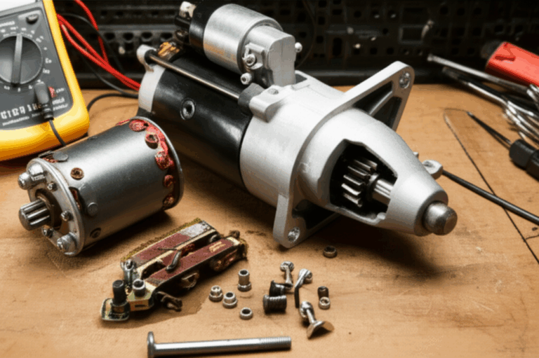
2) Multimeter testing for stators
- Continuity test for stators checks for open circuits. Verify each phase has continuity and matches expected resistance. Stator winding resistance issues show up as a high or low reading relative to the other phases.
- Measure AC output (three phase stator common failures often produce one weak phase). Low or no output from one phase indicates a partial short or open circuit.
- Check for shorts to ground. Use a megohmmeter for insulation resistance test stator per IEEE Std 43. If you read very low megohms to the laminated core you likely have a ground fault stator defect.
3) Advanced diagnostics when available
- Hipot test for stators per IEC 60034-1 evaluates dielectric strength. Use with caution and correct limits to avoid collateral damage.
- Thermal imaging stator diagnostics reveal hot spots and poor cooling paths. A thermal image often shows blocked ventilation system issues in motors with fan cooling.
- Vibration analysis stator health checks can catch bearing failure and shaft misalignment before rub occurs.
- Winding temperature sensors and thermistors help confirm thermal cycling and inadequate cooling in operation.
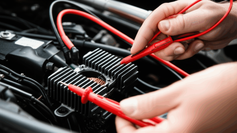
4) System checks
- Verify voltage regulator and rectifier output and ripple. Overvoltage points to regulator trouble. Excess ripple implicates the rectifier.
- Inspect the wiring harness for poor connections stator issues like loose terminals and corroded lugs. Clean and torque properly.
- Evaluate bearings and alignment. Bearing failure alternator stator rub scars the core and coils. Fix the mechanical cause or you will burn the next unit.
Document what you find. Photos and resistance readings help you identify recurring problems across a fleet.
Part 7: Material and Manufacturing Choices That Improve Stator Reliability
The stator’s life starts with the core and the winding system. Engineers and procurement teams can improve outcomes with the right specifications.
Material considerations
- Electrical steel grade and thickness:
- Choose steels with appropriate magnetic permeability and low core loss at your frequency. Non-oriented silicon steels (M-grades) are common for general-purpose motors. Grain-oriented steels are preferred for transformers not for rotating machines. Thinner laminations reduce eddy current losses which lowers temperature. If you need a deeper dive on material trade-offs see this overview of electrical steel laminations.
- Lamination insulation:
- The interlaminar coating must withstand your operating temperature and environment. Good coatings break up eddy currents and resist corrosion. Poor coatings raise eddy current losses and create localized heating.
- Winding wire and insulation class:
- Pick winding wire gauge that supports your amperage with margin. Select an insulation class that matches worst-case winding temperatures. Confirm dielectric strength for expected voltage spikes and overvoltage events.
- Varnish system and impregnation:
- Quality varnish penetrates the winding, bonds conductors, and improves heat transfer. It also resists oil and coolant exposure. Verify the varnish application stator quality through sample cross-sections or void content checks.
- Laminated core geometry and air gap:
- Maintain a consistent air gap to balance magnetic forces and reduce humming. Slot geometry affects copper fill and cooling.
Manufacturing and assembly processes
- Stamping vs laser cutting:
- High volume production often uses precision stamping with tight burr control to reduce magnetic flux leakage and eddy losses. Laser cutting suits prototypes and complex shapes. It may introduce a heat-affected zone that must be managed to protect magnetic properties and lamination insulation.
- Interlocking and bonding:
- Interlocking laminations act like LEGO bricks and build core stiffness without welding which can hurt magnetic properties. Bonded stacks reduce vibration and acoustic noise. Consider the impact on thermal paths and reworkability.
- Stack clamping and quality checks:
- Verify core squareness, stack height, and flatness. Laminated core stator issues often trace back to loose stacks that vibrate and abrade windings.
- Winding and connection quality:
- Watch for consistent winding tension, secure lacing, and robust terminations. Loose connections stator failures often show up at the first bump in the road.
- Cooling provisions:
- Size the ventilation system motor stator path for your worst-case ambient. A small change in fin geometry or fan flow can drop winding temperature and double insulation life.
To see typical constructions, geometry, and how laminations stack and align across motor platforms, take a look at motor core laminations and how different stack-up techniques influence loss, noise, and reliability. The same applies to stator core lamination in alternators, generators, and BLDC drives where slot design and stack integrity shape output and thermal behavior.
Part 8: Which Application Is This For? Best-Fit Guidance by Use Case
You will save time and money if you tailor material and process choices to the application. Here is a quick guide.
- Automotive alternators:
- Common issues: battery warning light, dim headlights, burning smell from alternator, and whining noise. Overheating from excessive electrical load and poor ventilation dominates. Bearing failure alternator stator rub accounts for a significant slice of returns.
- Recommendations: choose robust laminations with low core loss, upgrade varnish to withstand oil contamination, and maintain cooling shrouds. Inspect regulator and rectifier on every service. Confirm shaft alignment and rotor balance.
- Motorcycles and powersports (ATV and UTV):
- Why do motorcycle stators fail? Sustained high RPM and marginal cooling inside tight engine cases. Oil contamination and rectifier/regulator failures also play a role. ATV UTV stator common issues mirror this with added vibration from off-road use.
- Recommendations: verify rectifier regulator impact on stator by checking charging voltage and ripple. Select higher insulation class and varnish with strong chemical resistance. Improve airflow and heat sinking where possible.
- Industrial motors:
- Industrial electric motor winding failure analysis often reveals overloaded duty cycles, dust-clogged cooling, and misaligned shafts. Three phase stator common failures include turn-to-turn shorts from insulation breakdown and open circuits at lead connections due to vibration.
- Recommendations: perform load studies, clean fins and fans, align shafts, and monitor with vibration analysis. Use thermal imaging to detect hot spots. Consider higher grade silicon steel laminations and better stack bonding to reduce vibration.
- Generators:
- Generator stator burnout reasons include continuous overload and external short circuits on the output. Moisture ingress during storage and salt-heavy environments attack insulation and cause corrosion in stator windings.
- Recommendations: specify moisture-resistant varnish, maintain heaters or dehumidifiers in standby equipment, and perform periodic insulation resistance tests. Protect against external shorts with proper overcurrent protection and fault detection.
- Marine engines:
- Humidity impact on stators drives corrosion. Salt spray corrosion and oil contamination compound the problem.
- Recommendations: sealed connectors, corrosion-resistant coatings, and routine cleaning. Consider more frequent hipot and IR testing.
For BLDC drives and high power density aerospace or robotics applications you may consider thin laminations, high silicon content steels, or even cobalt alloys for extreme cases. You pay more yet gain lower core loss and higher magnetic flux density which lets you shrink the stack and reduce copper loss. For prototyping or complex shapes a stator core lamination produced with precision processes can shorten your iteration loop and help you validate air gap and slot geometry under real loads.
Part 9: Preventative Measures to Extend Stator Life
You can cut failure rates with simple habits and a few design shifts.
- Regular electrical system checks:
- Periodically verify charging voltage and ripple. Confirm no diagnostic trouble codes are lurking. Catch regulator and rectifier issues before they cook the stator.
- Ensure proper cooling and ventilation:
- Inspect fans, vents, and shrouds. Clean dust and debris from fins. Verify the fan works. Watch for poor ventilation stator overheating in confined spaces or hot climates.
- Maintain clean and secure connections:
- Tighten terminals, remove corrosion, and fix loose connections. Replace damaged wiring harness sections. Poor connections stator failures often start as simple voltage drops that create heat.
- Avoid sustained excessive electrical loads:
- Review accessory loads. In vehicles do not stack high draw aftermarket systems without alternator capacity headroom.
- Address mechanical issues early:
- Replace bearings on schedule. Fix shaft misalignment before it turns into rotor rub. Balance the rotor to reduce vibration induced stator failure.
- Choose materials with margin:
- Use laminations with lower loss. Select higher insulation class when ambient temperatures or load profiles demand it. Upgrade varnish for oil and coolant exposure.
- Environmental control:
- Improve sealing against moisture ingress. Use heaters or dehumidification for idle generators. Clean contamination promptly.
- Scheduled diagnostics:
- Include insulation resistance test stator checks during planned outages. Use thermal imaging and vibration analysis on critical motors. Store baseline data to flag drift.
A small investment in preventative maintenance saves you from regulator rectifier burnout stator events and unplanned downtime.
Part 10: Quick Reference Table — Failure Modes, Causes, and Impact
| Failure Mode | Primary Causes | Typical Symptoms | Estimated Occurrence / Impact | Relevant Industries / Notes |
|---|---|---|---|---|
| Insulation Breakdown | Overheating, voltage spikes, vibration, age, oil or moisture contamination | Burning smell, charring, short or open circuits, ground fault | Very high. Often the first step toward shorts. Insulation life drops fast with even modest temperature rise above rating | Automotive alternators, industrial motors, marine, power generation |
| Winding Short Circuit | Insulation breakdown, physical damage, moisture ingress, metallic debris, manufacturing defects | Overheating, reduced output, rapid battery drain, high current draw, breaker tripping | Common. A single shorted turn can drop alternator output and spike heat | Automotive, industrial motors, generators |
| Winding Open Circuit | Vibration fatigue, melted wire from overcurrent, poor joints, thermal cycling | No or intermittent output, one weak phase, engine stalling | Moderate. Hard to spot without continuity testing | Automotive, small motors, tools |
| Overheating (Thermal Degradation) | Excessive electrical load, poor ventilation or fan failure, high ambient temperatures, prolonged high RPM | Burning smell, darkened varnish, decreased output, leads to insulation breakdown | Extremely high. The most common precursor to stator failure | All applications with heavy load or poor airflow |
| Mechanical Damage | Severe vibration, foreign object ingress, rotor-stator rub from bearing failure or misalignment | Grinding or rubbing noises, visible core damage, seizure | Moderate to high depending on environment | Automotive, off-road vehicles, heavy machinery |
| Contamination | Oil or coolant leaks, dust/dirt, road salt, moisture | Insulation breakdown, short circuits, corrosion, reduced cooling | High in harsh environments. Marine and engine bays are common hotspots | Automotive, marine, mining, manufacturing |
Case studies in remanufacturing and field service consistently show that heat and contamination top the list of root causes which aligns with the physics above. Pair that with faulty regulators and bad bearings and you have the usual failure stack-up.
Part 11: Tying It Back to Laminations — Why Core Design Matters
You cannot fix a weak lamination stack with great windings. Core design drives magnetic efficiency and temperature rise. Thinner laminations cut eddy current losses. Better coatings keep those laminations electrically isolated. Clean edges and low burr reduce magnetic flux leakage that otherwise turns into heat. Stack tightness and bonding methods control vibration and noise which protects insulation.
If you are evaluating options across your program portfolio keep these points in view:
- Silicon steel laminations vs exotic alloys:
- Non-oriented silicon steels deliver a strong balance of cost and performance for most motors and alternators. They offer good permeability and acceptable hysteresis loss across typical frequencies. If you move to higher frequency or higher power density you may consider advanced alloys, yet you should always model the loss and temperature impact.
- Lamination thickness:
- Thinner means lower eddy current loss at the same frequency. The trade is cost and stamping complexity. Prototype with your target thickness so thermal results reflect reality.
- Slot geometry and copper fill:
- Slot shape affects winding density and cooling paths. High copper fill reduces copper loss yet can trap heat if varnish impregnation is poor. Balance both.
- Process selection:
- Laser cut for prototypes or complex low-volume shapes. Stamp for high volume and lower cost per piece. Keep an eye on insulation damage and burr formation either way.
If you want an overview of typical stack assemblies and integration paths across sectors, review how complete motor core laminations and focused stator core lamination solutions approach tolerances, bonding, and slot design to reduce loss and extend service life.
Part 12: Your Engineering Takeaway
Let’s boil it down to what you can use tomorrow.
- Overheating kills stators. Manage electrical load, improve airflow, and select laminations and insulation that keep temperatures in check.
- Electrical faults drive shorts and opens. Test for internal short in stator, phase-to-phase short, turn-to-turn short, and ground fault. Fix regulator and rectifier problems first.
- Mechanical issues matter. Stop vibration, correct shaft misalignment, and replace bearings early to avoid rotor rub and wire abrasion.
- Environment accelerates failure. Control moisture and contamination. Upgrade varnish and sealing for oil and coolant exposure.
- Material and manufacturing choices set the baseline. Choose low-loss electrical steel, control lamination burrs and coatings, and verify impregnation quality.
- Diagnostics pay back. Use continuity, resistance, insulation resistance, and when needed hipot testing per IEEE and IEC methods. Add thermal imaging and vibration analysis on critical assets.
- Design for your application. Motorcycle, automotive, marine, and industrial use cases impose different stresses. Match insulation class, lamination thickness, and cooling to the real load profile.
If you are designing or sourcing stators and want to reduce heat, improve stability under vibration, and extend service life, focus on the core. Better material selection plus process control on laminations gives you cooler operation and more headroom. For a quick perspective on lamination families, thickness options, and stack strategies at scale, you can scan these summaries on electrical steel laminations, motor core laminations, and application-driven stator core lamination.
Empowering Next Steps
- Pin down your failure mode. Pull one failed unit. Photograph the windings and core. Measure resistance and insulation. Note contamination. This confirms whether heat, electrical faults, or mechanical rub led the parade.
- Run a system check. Verify regulator and rectifier health, battery state, and connection integrity. Fix system issues before installing a new stator.
- Review your lamination spec. Confirm steel grade, thickness, coating class, burr limits, and bonding method. Stress test a representative core for loss and temperature rise at your frequency and load.
- Upgrade where the data says so. If thermal margin is thin move to lower loss laminations or better cooling. If vibration is high consider bonded stacks and improved lacing. If contamination is common specify a tougher varnish system.
- Build a preventive plan. Schedule cleanings, thermal scans, and periodic insulation resistance tests. Log data so you can spot drift early.
- Have a supplier conversation. Share your duty cycle, ambient conditions, target losses, and cost constraints. Ask for material options, trial stacks, and stack integrity data so you can compare stamping vs laser cut prototypes or bonding techniques objectively.
You are not guessing anymore. You have a clear map from physics to procurement decisions that will keep your machines running and your maintenance team happy.
Additional technical notes and terminology you may encounter during troubleshooting and design:
- Alternator stator failure often pairs with regulator issues which trigger voltage spikes and excessive current. Monitor for overvoltage DTCs and ripple on the DC bus.
- Generator output issues can originate from external shorts which back-drive the stator windings and overheat the core.
- Motor stator winding issues often hide in the connections where vibration turns tight joints into intermittent opens.
- Laminated core stator issues including eddy current losses, magnetic flux leakage, and copper loss drive heat even when the nameplate load looks fine on paper.
- A three phase stator with one weak phase can produce rough idle in engine-driven systems and humming in motors due to unbalanced magnetic fields.
- Poor ventilation stator overheating happens fast in dusty plants and hot climates. Adding a shroud cleaning schedule may double stator life.
Finally remember the simple truth. Keep the stator cool and dry, keep the system voltage stable, and keep the rotor from hitting the core. Do that and most stators will outlive the machine.
Count of internal links used: 4
- electrical steel laminations
- motor core laminations
- stator core lamination
- rotor core lamination
Each used once.