What Are the Symptoms of a Bad Stator? Stator Problems Explained for Vehicles, Motors, and Generators
Every design engineer and procurement lead runs into the same headache sooner or later. A machine or vehicle shows dim lights, odd voltage readings, or repeated battery failures. Operators say the engine dies at idle or stalls out while driving. You suspect the charging system. Then the question hits you. Are these the symptoms of a bad stator, or is it the alternator, regulator, wiring, or simply a tired battery?
You’re in the right place. I’ll break down the symptoms in plain language, connect them to the physics and construction of the stator, and then guide you through practical test methods and material choices that prevent problems upstream. Think of this as a field-tested explainer for engineers, product designers, and buyers who want both clarity and confidence.
In short, we’ll use the Problem – Explain – Guide – Empower model:
- Problem: How do you recognize and confirm a stator fault without chasing ghosts
- Explain: What a stator does, why laminations matter, and how failure modes show up as real-world symptoms
- Guide: Materials, manufacturing, and design options that reduce risk in the first place
- Empower: Clear diagnostic steps and purchasing checklists you can use today
You’ll see dozens of practical terms along the way too. If you came here searching “how to test a stator,” “bad alternator symptoms,” or “charging system failure,” you’ll get actionable answers without fluff.
In This Article
- Why the Stator Matters in Your Charging and Electrical System
- Primary Symptoms of a Failing Stator
- Secondary and Less Obvious Symptoms
- How to Tell Stator Problems from Battery, Alternator, and Regulator Issues
- The Engineering Fundamentals: Laminations, Core Loss, and Failure Modes
- How to Test a Stator: Multimeter and Shop Diagnostics
- Your Options: Materials and Manufacturing Choices that Prevent Failures
- Which Application Is This For? Automotive, Motorcycle/ATV/Marine, Generator, and EV
- Action Plan: What to Do If You Suspect a Bad Stator
- Quick Reference Table and Key Codes You Should Know
- Your Engineering Takeaway
Why the Stator Matters in Your Charging and Electrical System
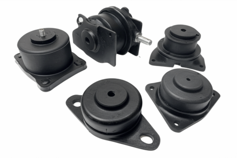
The stator lives at the heart of a charging or drive system. In an automotive alternator, the stator is the stationary set of coils and laminated steel core that generates AC when the rotor’s magnetic field spins past. A rectifier and voltage regulator then convert and control that output to DC for the battery and electrical loads.
If the stator underperforms or fails, the entire electrical system feels it. Lights dim or flicker. Batteries die early. ECUs log low or high system voltage codes. The root cause often traces back to the stator windings, the electrical steel laminations, the insulation system, or heat and vibration that push everything over the edge.
Key entities you’ll see in play:
- Stator, rotor, rectifier, voltage regulator
- Electrical steel laminations and insulation coatings
- Coil windings, diodes, bearings, serpentine belt
- ECU/ECM, wiring harness, fuses, chassis ground
Let’s map symptoms to the stator first, then we’ll open the hood on the physics and the manufacturing choices that drive reliability.
Primary Symptoms of a Failing Stator
Here are the big red flags you can’t ignore. These apply across vehicles, motorcycles, ATVs, marine engines, and generator sets. The details change by platform yet the pattern holds.
Weak or Dead Battery
- Battery constantly draining
- Vehicle struggles to start or won’t start
- Frequent jump-starts required
- Battery not holding charge after a drive
Why it happens: The stator isn’t generating enough power to recharge the battery. In a healthy system the alternator maintains 13.5 to 14.7 V DC at the battery under normal loads. Undercharging leads to sulfation and premature battery failure. Over time the starter motor has to work harder which accelerates wear.
Related keywords you might have searched:
- Dead battery causes
- Weak battery charge
- Battery discharge warning
- Low voltage warning
- Battery terminal corrosion
- Swollen battery casing
Dim or Flickering Lights
- Headlights, taillights, and dashboard lights dim at idle
- Flickering headlights and pulsating lights while driving
- Headlight dim at idle in particular
Why it happens: You’re seeing inconsistent voltage from the charging system. A partially failed winding or a ground fault causes ripple or reduced output. At low RPM, the effect shows up as dimming or flicker. At higher RPM, it may stabilize or it may worsen if the fault is thermal.
Keywords tied to this symptom:
- Flickering headlights
- Dimming lights when driving
- Pulsating lights car
- Dashboard lights dim
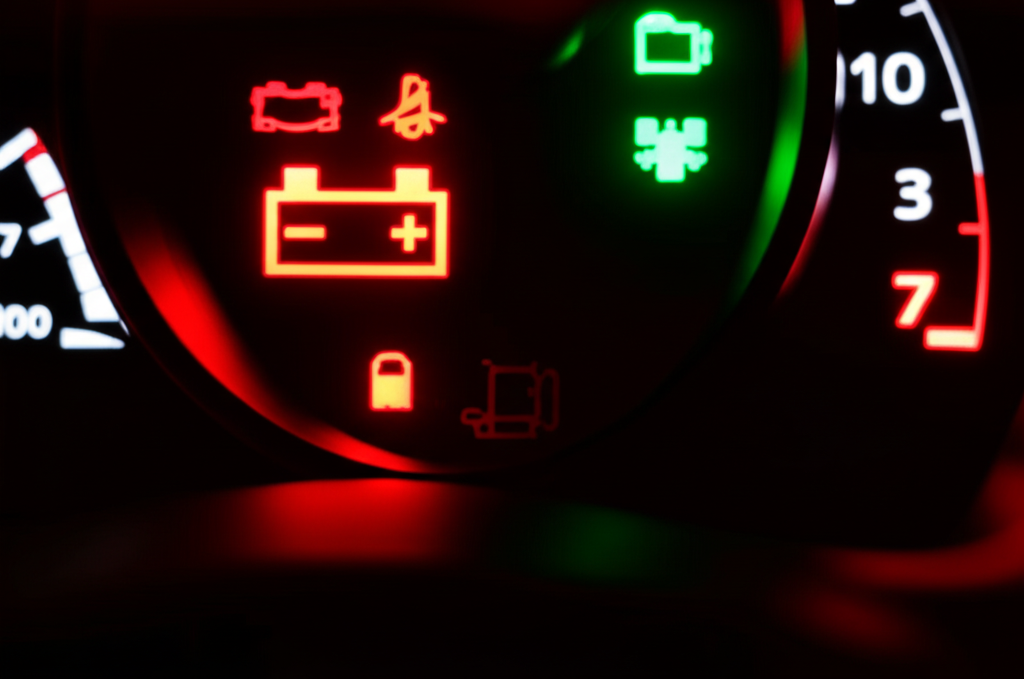
Battery/Charge Warning Light On
- Illuminated battery or charging system light on the dash
- Some vehicles show a “Check charging system” message
Why it happens: The ECU/ECM detects charging system failure or voltage out of expected range. You may see DTCs like P0562 (low system voltage) or P0622 (generator field not switching).
Keywords to note:
- Charging system warning light
- Battery discharge warning
- P0562 low system voltage
- P0622 generator field not switching
Secondary and Less Obvious Symptoms
These symptoms show up in more complex ways. They can mislead a team into chasing fuel or ignition problems when the root cause is electrical.
Engine Stalling While Driving
- Engine dies unexpectedly and may restart after a brief wait
- Roadside breakdown risk increases
Why it happens: Ignition and fuel systems depend on stable voltage. When the stator output drops, your ECU, ignition coils, fuel pump, and injectors can brown out. The engine stalls. You might also see “engine cranks but won’t start” after a stall if the battery then drains.
Keywords:
- Engine stalling while driving
- Engine dies unexpectedly
- Engine cranks but won’t start electrical
- No power accessories
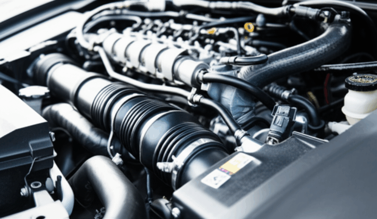
Unusual Noises from the Engine Bay
- Whining, grinding, buzzing from alternator area
- Alternator whine in the radio
- Bearing noise from alternator or alternator fan noise
Why it happens: Noise usually signals failing bearings or mechanical issues on the rotor side, not the stator itself. That said a severe stator short can overload the alternator and generate heat which accelerates bearing failure or belt slip.
Keywords:
- Bearing noise alternator
- Alternator whine radio
- Alternator fan noise
- Serpentine belt slipping
Burning Smell
- Burning rubber suggests belt slip under load
- Acrid smell hints at burning electrical insulation or overheated windings
Why it happens: High resistance connections or shorted turns raise temperature. Insulation bakes. You may also see smoke in severe cases.
Keywords:
- Burnt smell from car
- Smell of burning rubber (belt)
- Smell of burning plastic (wiring)
- Overheating alternator
Malfunctioning Electrical Accessories
- Power windows slow
- Wiper blades slow
- Heater fan weak
- Radio cuts out
- A/C and power steering issues with electric assist
Why it happens: Non-critical loads sag first when voltage falls. You can see erratic gauge readings too.
Keywords:
- Power window slow
- Wiper blades slow
- Heater fan weak
- Erratic gauge readings
- ABS light electrical
- Traction control light electrical
- Power steering issues electrical
- Blown fuse for accessories
Engine Performance Issues
- Rough idling engine and misfire symptoms
- Loss of power engine and RPM fluctuations
Why it happens: Ignition energy drops when system voltage falls. ECU logic may trip into protective modes under low voltage which affects ignition timing and fuel delivery.
Keywords:
- Rough idling engine
- Misfire symptoms electrical
- RPM fluctuations stator
- Loss of power engine
How to Tell Stator Problems from Battery, Alternator, and Regulator Issues
Let’s make this practical. You want a clean decision tree.
- Stator vs. Battery
- If a fully charged battery passes a load test but quickly discharges after driving, suspect charging output. If the battery fails a load test or shows a swollen casing and high internal resistance, suspect the battery first.
- Look for P0562 low voltage and logs of under-voltage events.
- Stator vs. Alternator (full unit)
- In automotive systems, you usually replace the entire alternator, not just the stator. Still, you can isolate fault modes. A diode test may flag a rectifier fault. Bearing noise points to mechanical failure. Low AC ripple after the rectifier hints at healthy diodes but possibly weak stator output.
- Stator vs. Voltage Regulator
- Overcharging battery symptoms such as 15 V to 16 V at the battery point to a failed regulator more than a stator problem. Undercharging can be stator, regulator, or wiring. Confirm with DC voltage test at the alternator output and at the battery with and without loads.
- Don’t forget wiring and grounds
- Loose battery terminals, corroded electrical connections, and poor chassis ground mimic charging failures. A voltage drop test across major cables saves hours.
The Engineering Fundamentals: Laminations, Core Loss, and Failure Modes
What does a stator do? It converts a changing magnetic field into electrical power. The stator core uses thin, insulated electrical steel laminations to guide magnetic flux efficiently with minimal loss. The coil windings sit within slots in that laminated core. In alternators, the rotor’s magnetic field spins past the stator and induces AC. In many motorcycle and ATV systems, a permanent magnet rotor excites the stator directly and a regulator-rectifier handles conversion and control.
Why laminations matter:
- Eddy currents act like tiny whirlpools in a river. They swirl in the steel when fields change and convert energy into heat. Thinner, insulated laminations break up those whirlpools and slash eddy current loss.
- Hysteresis loss depends on material coercivity and the B-H curve. Materials with lower coercivity switch magnetization with less energy which cuts heat and boosts efficiency.
- Insulation coatings on each lamination block inter-laminar currents. Burrs or welds that bridge laminations increase loss and local heating.
Relating these fundamentals to symptoms:
- Overheating of the alternator can come from high core losses in poor-quality laminations or compromised insulation. That heat then bakes winding insulation which leads to open circuit stator faults or short circuit stator faults.
- A ground fault stator (winding shorted to core) drops output and triggers DTCs for low system voltage. It may also trip protective circuits in the voltage regulator.
- Stator coils burnt or discolored signal prolonged overload or poor cooling. They often produce intermittent problems as heat rises then fades with cool-down which explains intermittent electrical issues that drive techs crazy.
Common stator failure modes engineers track:
- Open circuit stator due to broken lead or burned winding
- Short circuit stator due to turn-to-turn short
- Ground fault stator where winding insulation fails to the core
- Stator winding damage from vibration or slot liner wear
- Field coil failure in wound-field alternators
- Rectifier bridge failure and voltage regulator failure symptoms that masquerade as a bad stator
If you design or buy stators, the quality of the electrical steel laminations and the insulation system play a central role in reliability, heat rise, and life.
How to Test a Stator: Multimeter and Shop Diagnostics
You don’t need a lab to find most stator faults. A multimeter and methodical steps go far. If you have an oscilloscope, even better. Here’s a practical progression.
1) Visual Inspection
- Check belt alignment and tension if it’s an automotive alternator. A slipping serpentine belt causes low output and a smell of burning rubber.
- Inspect connectors, the wiring harness, and battery terminals for corrosion.
- Look for signs of overheating alternator housing or burnt insulation smell.
2) Battery Baseline
- Fully charge the battery, then measure open-circuit voltage. A healthy battery sits around 12.6 V.
- Perform a load test if available. A weak battery muddies the water.
3) DC Voltage Test Alternator
- With the engine idling, measure voltage at the battery. Expect roughly 13.5 to 14.7 V for most systems.
- Increase RPM and switch on loads like headlights and the heater fan. Watch for undercharging (dropping below 13 V) or overcharging (climbing above 15 V), which suggests regulator trouble.
4) Voltage Drop Test
- Measure across the positive cable from alternator output to battery positive under load. You want minimal drop. Do the same across the ground path. High drop means cable, connection, or chassis ground problems, not a stator defect.
5) Multimeter Test Stator (where accessible)
- For motorcycle stators or some alternators with accessible phases, measure AC voltage output across each pair of stator leads with the engine running. Phases should match. A low phase points to a winding issue.
- Stator resistance check: measure across each pair of stator leads with the engine off. Compare to service specs. Extremely low resistance may indicate a short. Infinite or very high resistance may indicate an open.
- Continuity to ground: check between each stator lead and ground. You should see no continuity. Any reading suggests a ground fault stator.
- AC voltage test stator helps confirm balanced output across phases. A large mismatch is a red flag.
6) Diode Test Alternator
- In automotive alternators, test rectifier diodes with a multimeter. A failed diode reduces output and increases ripple which causes flickering lights and alternator whine in the radio.
7) Parasitic Draw Test
- If the battery dies overnight with a known healthy charging system, measure current draw with the vehicle off. Excess draw suggests a wiring or module issue, not a stator defect.
8) Scan for Diagnostic Trouble Codes (DTCs)
- Look for P0562 low system voltage or P0563 high system voltage. P0622 indicates generator field not switching. You may also see ABS light electrical or traction control light electrical when voltage sags.
9) Oscilloscope Checks (advanced)
- View ripple on the DC bus under load. Excess ripple hints at a rectifier problem or a shorted stator phase.
A quick note on overcharging:
- Overcharging battery symptoms, like 15 V to 16 V readings, usually track back to the voltage regulator. The stator rarely causes overvoltage by itself.
Your Options: Materials and Manufacturing Choices that Prevent Failures
If you’re designing or sourcing stators, you can prevent many symptoms above with the right materials and processes. Here’s a balanced guide.
Material Considerations
- Nonoriented Silicon Steels (NOES)
- The go-to choice for rotating machines. Available in various thicknesses like 0.50, 0.35, and 0.27 mm. Thinner laminations reduce eddy current loss at higher frequencies and speed.
- Pros: Well understood, cost effective, strong supply base.
- Cons: At extreme power density you may need premium grades with tighter loss specs.
- Grain-Oriented Silicon Steel (GOES)
- Designed for transformers with strong anisotropy. Great for transformers and inductors, not typical for stators in rotating machines. Still useful context for teams that build both motors and transformers.
- Cobalt Alloys
- High saturation flux density and excellent at elevated temperatures. You see them in aerospace or high power density motors where every percentage of efficiency matters.
- Pros: Higher torque density and lower core loss at high frequency.
- Cons: High cost and supply constraints. Use only when the application demands it.
- Insulation Coatings
- Classify by interlaminar resistance, punchability, and thermal endurance. The coating must survive stamping or laser cutting without flaking. It must maintain isolation after stacking and assembly.
- Poor coatings increase eddy currents, raise temperature, and shorten winding life.
A quick reality check: lamination quality and thickness directly influence heat rise under load. That heat accelerates winding insulation aging which leads to open circuit stator events or short circuit stator failures you later see as “engine dies unexpectedly” or “vehicle won’t start.”
If you need a primer on core components, the quality of the stator core lamination and how it interfaces with slot liners, wedges, and windings has an outsized impact on real-world performance.
Manufacturing and Assembly Processes
- Stamping
- Best for high-volume production. Tooling cost pays off as volumes climb. Watch for burr height which bridges laminations. Manage die wear, tool clearances, and deburring.
- Pros: Speed and cost for scale.
- Cons: Upfront tooling and potential burrs.
- Laser Cutting
- Ideal for prototypes and complex geometries. Precise and flexible. Heat-affected zones can raise local loss which you can mitigate with process optimization.
- Pros: No tooling, fast iteration.
- Cons: Slower per part and potentially higher core loss if process is not dialed in.
- Wire EDM or Waterjet
- Niche options where you need exceptional precision with minimal heat impact. Slower but very clean edges.
- Annealing
- Post-process annealing can restore magnetic properties after cutting. Critical when stamping or laser cutting introduces stress. Follow material supplier guidance closely.
- Stacking and Bonding
- Interlocking laminations work like LEGO bricks. You get rigidity without welding that can cause localized shorts or heat-affected damage.
- Bonding with resin or adhesive films improves stiffness and acoustic behavior. It also reduces vibration that rubs slot liners and harms windings.
- Welding has a place yet use it carefully. Avoid bridging across laminations which increases eddy currents.
- Winding and Insulation System
- Slot liner material and thickness, wedge retention, and varnish impregnation all matter. Vibration will rub through insulation faster than you think.
- Proper varnish impregnation improves thermal performance and mechanical stability which reduces “stator coils burnt” events.
- Tolerances and Fit
- Stack height, roundness, and slot geometry tolerances support consistent air gap. A controlled air gap keeps magnetic loading where you designed it.
- Pay attention to rotor-stator alignment. It affects noise, bearing life, and efficiency.
If you’re coordinating a family of products or building platforms across voltages and frequencies, consider standardizing around proven motor core laminations to reduce project risk and lead time.
Which Application Is This For? Automotive, Motorcycle/ATV/Marine, Generator, and EV
Different platforms use different stator topologies and power electronics. The symptoms look similar yet the root causes and tests differ a bit.
- Automotive Alternators
- Wound-field rotor and three-phase stator. DC output after rectification. Regulator controls field current.
- Common symptoms: battery light, dim at idle, whining under load, DTCs like P0562 and P0622.
- Overcharging usually points to the regulator, not the stator.
- Motorcycle and ATV Stators
- Permanent magnet rotor with three-phase stator. Regulator-rectifier shunts or bucks power.
- Common symptoms: burned stator coils, melted connectors, intermittent output at high RPM, no spark condition in some systems where ignition feeds from the stator.
- Tests: AC phase voltage, stator resistance check, and ground fault tests are quick and definitive.
- Marine Stators
- Similar to motorcycle designs in many outboards. Corrosion and moisture ingress add failure paths.
- Watch for wiring harness damage, corroded electrical connections, and ground faults that come and go with vibration.
- Generator Stators
- Output goes to an AVR or rectifier depending on design. Symptoms include unstable AC output, overheating, and failure under load.
- Oscilloscope checks help capture erratic output. Thermal imaging during load tests can catch hot spots early.
- EV Motors and High-Frequency Applications
- BLDC and PMSM stators run at higher electrical frequencies. Core loss rises with frequency which puts a premium on lamination thickness and material choice.
- Designs may use hairpin windings for improved slot fill. Keep an eye on partial discharge risks with higher voltages.
In rotating machinery the rotor matters too. Air gap geometry and magnetic circuit balance depend on it. When you need parity across both sides of the air gap, partner suppliers must deliver consistent rotor core lamination stacks that match your stator performance goals.
Action Plan: What to Do If You Suspect a Bad Stator
- Do quick checks first
- Inspect belt, connectors, grounds, and fuses. Fix obvious issues.
- Check battery health. Replace it if it fails a load test.
- Measure, don’t guess
- Run DC voltage test at the battery with loads at idle and higher RPM.
- Do a voltage drop test on positive and ground sides.
- Perform a multimeter test stator where you can access phases. Check AC balance, resistance, and ground faults.
- Decide on repair vs. replacement
- In automotive settings, swapping the alternator unit is often the practical move. In motorcycles and ATVs, you can replace only the stator and regulator-rectifier.
- Consider the regulator too. Overcharging and undercharging often implicate it.
- Safety and downtime considerations
- Driving with a bad stator risks complete breakdown. You could damage the battery, ECU, fuel pump, or sensitive electronics.
- If you see burnt insulation or smell acrid smoke, stop and address it. Fire risk isn’t worth pushing another mile.
- Cost and lifecycle thinking
- Stator replacement cost varies widely by platform. The bigger lever is preventing failure in the first place with better materials and manufacturing choices.
- Average stator lifespan depends on duty cycle, cooling, vibration, and material grade. Good design and clean power electronics stretch life meaningfully.
- For design and procurement teams
- Specify lamination grade and thickness based on frequency and loss targets.
- Lock down insulation class and varnish processes that match your thermal profile.
- Document burr limits, interlaminar resistance targets, and post-process annealing where needed.
- Use supplier PPAP-like documentation even for non-automotive programs. You want repeatability, not surprises.
Quick Reference Table: Stator Failure Symptoms, Likelihood, and Diagnostic Insights
| Symptom Category | Specific Symptom | Likelihood of Bad Stator | Common Stator Failure Mode | Diagnostic Insight | Impact if Ignored |
|---|---|---|---|---|---|
| Charging System Failure | Battery warning light on | High | Open/short in windings | Battery voltage below 13.5 V with engine running | Vehicle shutdown and battery damage |
| Charging System Failure | Repeatedly dead or weak battery | High | Short to ground or open circuit | Battery passes load test yet loses charge after driving | Stranded and starter wear |
| Starting | Vehicle won’t start or weak crank | High | Severe output loss | Jump-start helps briefly then dies again | Immobilized vehicle |
| Electrical Output | Dim or flickering headlights/interior lights | Medium | Partial winding failure | Dimming at idle and voltage ripple | Safety risk and poor visibility |
| Accessories | Slow windows, weak wipers, radio cuts out | Medium | Reduced and unstable output | Low voltage under load with accessories on | Electronics stress and user complaints |
| Overcharging | Battery at 15 V+ | Low for stator | Regulator fault | DC voltage too high at battery | Battery damage and electronics risk |
| Engine Performance | Engine stalling while driving | High | Power loss to ECU/ignition/fuel | Low voltage DTCs and immediate restart issues | Roadside hazard |
| Auditory/Olfactory | Whining/grinding, burning smell | Low to medium | Bearing or insulation failure | Noise rises with RPM, acrid smell present | Full alternator failure and fire risk |
| DTCs | P0562, P0563, P0622 | Medium to high | Under/overvoltage or field control fault | Scan tool confirms codes | Component damage if ignored |
What Causes Stators to Fail and How to Prevent It
Why do stators fail? You’ll see the same core drivers in postmortem reviews.
- Thermal overload
- High ambient temperature, poor airflow, or high electrical losses bake windings. Hysteresis and eddy current loss climb with frequency and flux density which means material choice and thickness matter.
- Vibration and mechanical rub
- Poor retention or resonance rubs through slot liners. The first sign is intermittent shorts. The next is a full ground fault stator.
- Moisture and contamination
- Corrosion at connectors or wicking into windings breaks down insulation. Marine and off-road applications need extra sealing and potting discipline.
- Power electronics stress
- Overcurrent, poorly damped transients, or regulator failures stress the stator thermally. Overcharging battery symptoms tell you the regulator is out of spec which can also overheat windings.
- Manufacturing defects
- Burrs that bridge laminations increase loss. Inconsistent varnish impregnation leaves hotspots. Poor quality control shows up months later as warranty claims.
Preventative maintenance electrical teams can act on:
- Routine voltage checks and parasitic draw tests
- Infrared scans during load tests on generator sets
- Connector inspection and dielectric testing at service intervals
- Cleaning and securing grounds and battery terminals
If you want a single lever to pull upstream, invest in lamination quality and consistency. For a broad portfolio or to build capability across programs, start by aligning on your baseline specs for core lamination stacks. That one choice pays dividends in reduced losses, lower operating temperature, and longer winding life.
Key Terms and Quick Definitions
- Stator vs. Alternator
- The stator is the stationary core and windings. The alternator includes the rotor, rectifier, and regulator too.
- Regulator-Rectifier
- In permanent magnet systems, this module converts AC to DC and regulates voltage by shunting or bucking current.
- Eddy Current and Hysteresis Loss
- Eddy currents are circulating currents in the steel that create heat. Hysteresis loss is the energy cost to flip magnetic domains each cycle.
- Continuity, Resistance, and Voltage Drop
- Continuity checks for a closed path. Resistance measures opposition to current. Voltage drop reveals hidden losses across cables and connections.
- DTCs You’ll See
- P0562 low system voltage
- P0563 high system voltage
- P0622 generator field not switching
Frequently Overlooked Clues You Can Validate in Minutes
- Alternator whine in the radio tracks ripple and diode issues
- Dim at idle but normal at higher RPM hints at belt slip or partial stator weakness
- Fuse blowing repeatedly suggests wiring harness damage or ground faults
- ABS/Traction lights show up during low voltage events which points back to charging problems
- Overheating alternator and a smell of burning plastic indicate insulation trouble
- Diagnostic trouble codes combined with a voltage drop test give you a fast yes or no on wiring vs. stator
Sources and Standards You Can Trust
If you need to tighten specifications or audit materials, point to published standards and test methods.
- IEC 60404 series for magnetic materials characterization and loss measurement
- ASTM A677 for nonoriented electrical steel sheet and strip
- Manufacturer data sheets for NOES and cobalt alloys with core loss curves at target frequencies
- OEM service manuals for specific DC voltage test alternator procedures, multimeter test stator specs, and diode tests
- SAE and ISO documents for automotive electrical systems and voltage regulation where applicable
These references help you move from tribal knowledge to repeatable requirements which protects performance and cost.
Your Engineering Takeaway
- Symptoms to watch
- Battery light on, dim or flickering headlights, weak or dead battery, engine stalling, burning smell, whining noise, slow power accessories, erratic gauges, and low voltage DTCs like P0562.
- How to confirm
- Start with a DC voltage test at the battery. Run a voltage drop test on cables. Use a multimeter to do stator resistance check, AC voltage test stator on each phase, and ground fault checks. Scan for codes. Verify the regulator before blaming the stator for overcharging.
- Why it failed
- Heat, vibration, moisture, bad power electronics, or manufacturing defects. Laminations, insulation, and assembly quality drive reliability.
- What to design and buy
- Choose lamination grade and thickness for your frequency and loss targets. Control burrs, coatings, annealing, and stacking. Design robust winding insulation systems. Verify with supplier data and process controls.
- What to do next
- If you suspect a bad stator, do the quick tests above. For automotive systems, consider replacing the alternator assembly. For motorcycles, ATVs, and marine engines, replace the stator and possibly the regulator-rectifier. For design programs, engage your lamination supplier early with performance targets, thermal limits, and mechanical constraints.
If you want help evaluating the trade-offs between lamination grades, thickness, and stacking methods for your next platform, schedule a technical review with your preferred supplier. The decisions you make now will show up as cooler running machines, longer service life, and fewer warranty headaches later.
And if you’re building a product family where stators and rotors must scale cleanly across variants, lock in your lamination strategy early. Your materials and processes will determine whether your customers ever see dim lights, flickering dashboards, or battery lights at all.