What Are Stator Windings? A Hands‑On Guide From the Shop Floor
Introduction: The Core Component of Electric Motors and Generators
When I first opened a motor in a cramped plant room, I expected gears or something mechanical. Instead I found copper coils tucked neatly into a steel core. That moment changed how I think about motion and electricity. Stator windings sit at the heart of electric motors and generators, yet most folks never see them. They convert electrical energy into magnetic fields in motors. They do the reverse in generators.
In this guide I’ll share how stator windings work, the types you’ll encounter, how they fail, and how I test and maintain them. I’ll focus on simple explanations with enough technical depth to help you diagnose real machines. If you work with motors or generators, or you’re just curious about what’s inside, you’re in the right place.
Table of Contents
Stator Windings Defined: What They Are and Why They Matter
The Stator as a Stationary Part
Start with the basics. The stator is the stationary part of an electric machine. The rotor sits inside and spins across a small air gap. In induction motors the rotor often uses a squirrel cage made from rotor bars and end rings. In synchronous motors the rotor carries field windings or permanent magnets. The stator surrounds that rotor with a magnetic circuit built from a stack of thin steel sheets called laminations. These laminations funnel magnetic flux and cut core losses.
Anatomy of a Winding
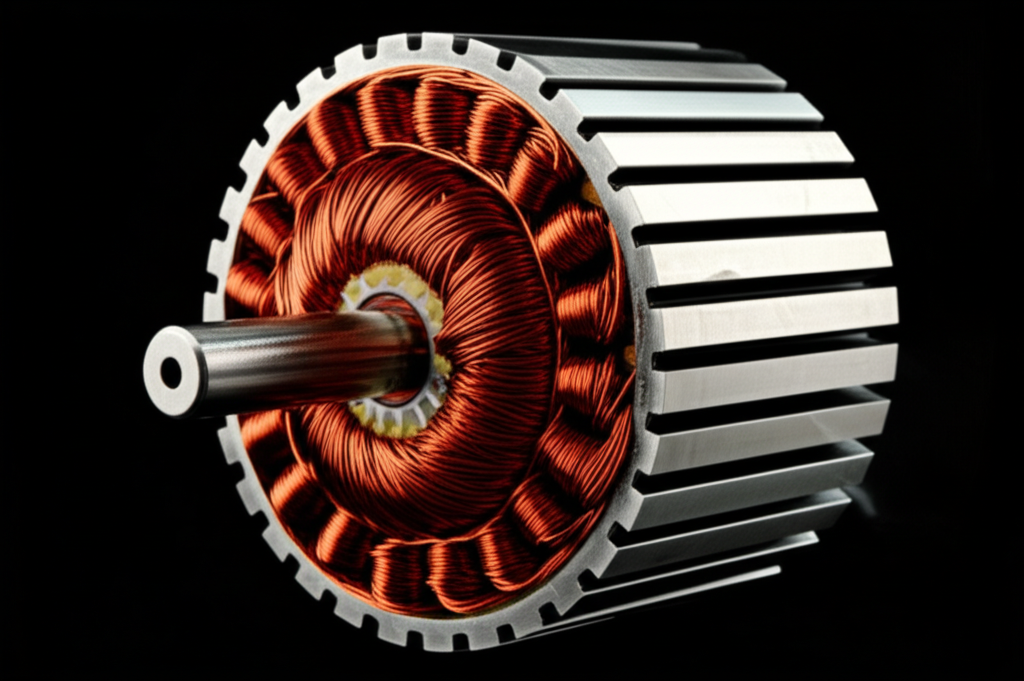
So what is a stator winding. Picture insulated copper wire formed into coils. We place those coils into slots in the stator core. The wire can be copper or aluminum. Copper wins on conductivity. Aluminum wins on weight and cost. Each slot gets a slot liner. The coil wire itself has enamel insulation. We tie everything down with wedges, lacing, and phase separators. Then we impregnate the whole assembly with varnish under vacuum pressure. That process locks the coils in place, improves thermal conduction, and boosts dielectric strength.
If you looked at a stator winding diagram you’d see:
- Slots around the inner circumference of the core.
- Coils that span specific numbers of slots to create the right pole pitch.
- Phases arranged 120 electrical degrees apart in a three-phase machine.
- Leads that connect to terminals in star (wye) or delta.
It’s simple in principle. The details matter a lot.
The Primary Purpose
In motors the purpose of stator windings is to create a rotating magnetic field when AC current flows. That rotating field induces currents in an induction motor’s rotor or locks to a magnetized rotor in a synchronous motor. Torque follows. In generators we spin the rotor to change magnetic flux through the stator. That changing flux induces voltage and current in the stator windings according to Faraday’s Law of Induction. Lenz’s Law tells us the induced currents oppose the change in flux which is why generators fight you when you load them.
How Stator Windings Work: The Principles of Electromagnetism
I promise not to bury you in equations. You only need a few ideas.
In Electric Motors
Feed alternating current into the stator windings. Each phase carries current that rises and falls in a sine wave. Place the phases around the stator in a specific pattern. The combined effect produces a rotating magnetic field. That field sweeps across the air gap. The rotor sees changing flux which induces current and magnetic fields in the rotor bars if it’s an induction motor. The rotor chases the rotating stator field which creates torque.
In synchronous motors the stator windings still produce the rotating field. The rotor has a DC-fed field winding or permanent magnets. The rotor locks in step with the stator field. That lock gives precise speed control at synchronous speed.
Three practical points I’ve learned:
- Back EMF grows with speed and cuts the net current in the winding. That is why no-load current stays modest even at high RPM.
- Inductance of the windings resists rapid current changes which filters the waveform and sets dynamic response.
- Winding shape and distribution control harmonic content. Fewer harmonics means smoother torque and less noise.
In Electric Generators
Reverse the story. Spin the rotor past the stator windings. The magnetic field sweeps by and the magnetic flux linkage through the coils changes with time. That changing flux induces EMF according to Faraday’s Law. The waveform depends on the winding distribution, the air gap, and the magnetic circuit.
Alternators in cars, wind turbine generators, and hydroelectric generators all use the same principle. You move magnetic fields past conductors. The finer points make or break performance:
- Magnetic flux density should be high but not so high that you hit core saturation.
- The air gap must be uniform. A wobble or eccentric rotor drops efficiency and adds vibration.
- Distributed windings yield a cleaner sinusoidal voltage. Concentrated windings raise space factor and power density at the expense of more harmonics.
AC vs DC Contexts you should know
You’ll see stator windings in both AC and DC contexts.
- AC induction motors: Stator carries the AC windings. Rotor uses a squirrel cage.
- Synchronous motors: Stator is AC. Rotor has field windings or permanent magnets.
- Brushless DC (BLDC) motors: The “DC” refers to the drive method. The stator has AC windings driven by electronic commutation from a DC source. Permanent magnets sit on the rotor.
- DC motors with commutators: Traditional DC motors place the armature windings on the rotor with a commutator and brushes. The stator often uses field windings or permanent magnets. Some specialty DC machines still carry stator windings for fields.
So the phrase “stator winding” shows up in many machines. The function stays consistent. Make a magnetic field or harvest a changing one.
Types and Configurations of Stator Windings
This is where real machine design lives. I learned early that the winding pattern sets the tone for efficiency, torque ripple, heat, and even how nice a motor sounds.
By Phase: Single-Phase vs Three-Phase
- Single-phase windings: You’ll see these in small appliances, HVAC fan motors, and fractional horsepower drives. A single-phase motor can’t self-start with only a main winding. It needs an auxiliary winding with a phase shift using a capacitor or a shaded pole to create starting torque. Main winding vs auxiliary winding decisions affect start torque, efficiency, and noise.
- Three-phase windings: Standard for industrial motors and generator sets. Three-phase power gives a naturally rotating field with smooth torque. You get higher power density and better efficiency.
By Winding Pattern and Arrangement
- Concentric windings: Coils with different spans nest inside each other. Concentric groups can simplify manufacturing and fit short end-turns which saves copper.
- Lap windings: Coils overlap adjacent slots. Designers use lap windings in higher current machines because parallel paths share current.
- Wave windings: Coils connect in series and “wave” around the core to raise voltage. These pop up where you want higher EMF without adding conductors in parallel.
- Distributed windings: Spread coil sides over multiple slots per pole per phase. Distributed windings smooth the waveform and cut harmonic distortion which reduces torque ripple.
- Concentrated windings: Pack coils into fewer slots per pole per phase. They raise slot fill factors and power density. Expect more harmonics and higher copper losses in end turns if you push too hard.
- Special cases: Fractional-slot concentrated windings in BLDC and servo motors deliver high torque density and compact stators which is why they dominate in drones, e-bikes, and robotics.
Your winding arrangement interacts with the magnetic circuit. Slot shape, tooth width, and the air gap geometry all influence magnetic flux density and losses.
Materials and Insulation Systems
- Conductors: Copper windings dominate because copper’s electrical resistance is lower which cuts ohmic losses. Aluminum windings save weight and cost for large machines and some HVAC gear. You trade a bit of copper loss for budget and weight.
- Insulation: Enamel coating on the wire forms the first line of defense. Slot insulation lines each slot and separates phases. After coil insertion we use varnish impregnation to lock everything in place. The varnish boosts thermal conductivity, resists partial discharge in high-voltage machines, and improves dielectric strength.
- Thermal class: Choose insulation class for your temperature rise. Higher classes handle more heat which extends life if you keep temperatures in check.
I learned the hard way that a great conductor without a robust insulation system leads to tears. Insulation defines reliability. Period.
The Critical Role and Importance of Stator Windings
Energy Conversion Efficiency
A well designed winding trims copper losses and reduces heat. Designers chase low resistance with thicker conductors and good slot fill. They also fight core losses with better steel and smarter tooth geometry. Core losses and copper losses both matter. You see them as stray heat and lower motor efficiency.
Winding layout affects power factor in induction motors because magnetizing current depends on turns, air gap, and the magnetic circuit. Good design reduces reactive current which helps power factor correction at the system level.
Reliability and Lifespan
The insulation system often becomes the weakest link. Heat ages insulation. Vibration rubs enamel away. Voltage spikes punch pinholes that grow into inter-turn shorts. Once a hot spot forms you risk thermal runaway. So cooling matters. Ventilated motors run cool with airflow. Totally enclosed motors protect against dust and moisture which avoids contamination driven failure.
I have pulled stators that looked brand new on the outside yet failed tests. The autopsy said moisture and long term partial discharge. Hidden problems kill machines quietly.
Versatility Across Applications
Stator windings show up everywhere:
- Industrial motors in conveyor lines and pumps.
- Generators in standby generator sets and utility plants.
- HVAC systems with fan motors and compressor drives.
- Automotive alternators feeding 12 V or 48 V systems.
- Wind turbines and hydroelectricity where slow mechanical rotation becomes three-phase power.
The same basic electromagnetism holds steady. Design details shift with application.
Common Stator Winding Failures and Maintenance
I’ve spent long mornings with a megger in one hand and coffee in the other. Testing saves downtime. It also saves budgets.
Causes of Failure
- Thermal overload: Overheating cooks enamel and varnish. Insulation degradation starts slow then accelerates. Poor cooling, high ambient temperature, and blocked vents make things worse.
- Voltage spikes and surges: VFDs can introduce steep dv/dt and reflected wave voltage. Lightning or switching surges can punch the insulation. Modern drives handle this better yet long leads still cause headaches.
- Mechanical stress and vibration: Loose end turns rub. Core vibration from electromagnetic forces agitates coils. Abrasion plus heat equals trouble.
- Environmental factors: Moisture lowers insulation resistance and fosters tracking. Dust and chemicals attack varnish.
- Ageing and dielectric breakdown: Time and stress do their work. Dielectric strength falls. Small defects turn into inter-turn short circuits.
Types of Winding Faults
- Inter-turn short: Two turns in the same coil short out. That raises local current and heat which can cascade into a bigger failure.
- Phase-to-phase short: Insulation between phases fails. You often see dramatic damage.
- Ground fault: A winding connects to the stator core or frame. Protective relays trip fast if they’re set up right.
- Open circuit winding: A broken lead, a failed joint, or a damaged coil. No current flows and torque or voltage drops.
Diagnostic Testing that actually works
Here’s my short list of tests I rely on for motor stator windings and generator stator windings.
- Insulation Resistance Test (Megger Test): Apply a DC voltage and measure insulation resistance to ground. Watch the polarization index for insight into moisture and contamination. Don’t megger electronics. Disconnect the drive or control first.
- Winding Resistance Test: Use a winding resistance meter to compare phase resistances. All three phases should match within a tight tolerance. A large mismatch points to a turn short or poor connection.
- Surge Comparison Test: High-frequency pulses compare windings under stress. This finds inter-turn faults that DC tests miss. I use this when a machine trips yet passes basic tests.
- Partial Discharge Analysis: In high-voltage machines PD detection catches early insulation defects. PD testing saved a generator rewind on one of my projects because we spotted the issue early.
- Additional tools: Motor circuit analysis and online monitoring with temperature and vibration sensors. They pair well with predictive maintenance programs.
If you ask me how to test motor windings effectively I’ll say start simple. Megger, resistance, then surge if needed. Escalate only when the basics point to trouble.
Repair, Rewinding, or Replacement
I weigh three things:
- Age and efficiency: Old machines without premium efficiency windings often waste power. A new motor may pay back fast.
- Extent of damage: Inter-turn shorts and ground faults across many coils push you toward a full rewind. Minor issues can be repaired.
- Critical application: For a plant critical pump I lean conservative and replace or rewind proactively.
Rewinding can maintain or even improve efficiency if the shop sticks to the original slot fill and winding geometry. Poor rewinds introduce extra copper losses and stray harmonics which heat the machine. Ask for data. Hold vendors to standards like NEMA and IEC requirements.
Advancements in Stator Winding Technology
I love where this space is heading. Materials and methods keep getting better.
Better Insulation Systems
New enamel chemistries and varnishes handle higher temperatures and higher dv/dt from modern drives. Improved slot liners, phase separators, and better impregnation processes raise dielectric strength. You see fewer partial discharge marks and longer life.
Smarter Geometry and Higher Power Density
Finite element analysis lets designers shape slots and tooth tips for the right magnetic flux density without saturating the magnetic core. Distributed windings get optimized for lower harmonic distortion. Concentrated windings tighten end turns and raise copper fill. The result is higher power density and better motor efficiency with less audible noise.
Integrated Sensing and Predictive Maintenance
I used to tape thermocouples to end turns and hope for the best. Now I see embedded RTDs, fiber-optic sensors, and online PD detection. Pair those with analytics and you get predictive maintenance that warns you before insulation degradation turns into a fault. That keeps lines running and people happy.
Practical Tips and FAQs from the Field
Here are the things I repeat to new techs and engineers.
- Stator vs rotor windings: Most AC motors put windings on the stator. Induction motor rotors use squirrel cage bars and end rings instead of rotor windings. Synchronous rotors carry field windings or permanent magnets. Generators often mirror this layout.
- AC and drives: Variable Frequency Drive (VFD) impact on windings is real. Harmonic distortion and steep voltage edges stress insulation. Use inverter-duty motors with better insulation systems and consider dv/dt filters or output reactors on long leads.
- Cooling and life: Motor cooling systems matter. Ventilated motors run cooler if they can breathe. Totally enclosed motors survive dirty air. Keep vents clear. Heat shortens life more than any single factor in my experience.
- Testing cadence: Build preventive maintenance into your schedule. Insulation resistance tests at regular intervals chart health. Add surge tests when you suspect inter-turn shorts. Move to predictive maintenance when budgets allow.
- Power factor and efficiency: Winding design sets magnetizing current which affects power factor. You can’t fix machine design with a capacitor alone. Power factor correction works at the system level. It doesn’t change motor copper losses or core losses in the stator.
- Standards: Know your NEMA motors and IEC motors requirements. Nameplate data tells you design letter, efficiency class, and thermal limits. Respect those limits.
- Materials and cores: The stator sits on a stack of electrical steel laminations that guide flux and reduce eddy currents. Quality here matters. If you want a deeper dive into the core hardware check these resources:
- The quality of the stator core lamination influences losses and temperature rise.
- Rotating hardware depends on the rotor core lamination layout which sets rotor reactance and performance.
- Modern machines rely on high grade electrical steel laminations to cut core losses.
- For BLDC and servo work take a look at specialized BLDC stator core options which enable high torque density.
- If you want a broad overview of options and stacks this page on motor core laminations helps.
- DC, BLDC, and stepper notes: DC motors with a commutator place armature windings on the rotor which is why brushes wear. BLDC motors shift windings to the stator with electronic commutation which eliminates brushes. Stepper and servo motors often use concentrated windings for precise control and high torque at low speed.
A quick story on VFDs and insulation
I once commissioned a pump with a long cable run to the motor. The drive was clean on paper. Two months later we saw insulation resistance slipping. The surge test exposed inter-turn weakness. We installed a dv/dt filter near the drive and the next motor lived a long happy life. Drives are great. Treat their voltage edges with respect.
A note on alternators and automotive work
Automotive alternators use stator windings in a three-phase layout with a rotating field on the rotor. The rectifier converts AC to DC for the battery. When folks say the alternator died they often mean a diode failed or the stator winding overheated from a bad belt or poor airflow. Basic checks go a long way. Spin it. Listen. Measure output. Don’t forget the grounds.
Flux linkage and the air gap
Flux linkage tells you how much magnetic flux actually links the coil turns. The air gap controls this more than most realize. A wider gap reduces linkage and raises magnetizing current which lowers efficiency. A tighter gap boosts linkage yet brings you closer to mechanical rub if clearances drift. Good machine design balances this trade-off.
Inductance and capacitance in windings
Windings have inductance and a little parasitic capacitance. Inductance slows current changes. Capacitance couples high frequency spikes across layers of the coil. VFDs excite that capacitance which causes common-mode currents. That is why you see shaft voltage and bearing currents in drive systems. Grounding and filters help.
When to rewind vs replace
If a critical motor fails and the frame, core, and rotor are in great shape, a quality rewind usually pays off. If the machine runs 24/7 with poor efficiency then a premium efficiency replacement can beat a rewind on lifecycle cost. Ask for loss measurements or test certificates from your rewind shop. You want to avoid extra copper losses or stray harmonic heating from sloppy work.
Conclusion: Powering Our World, One Coil at a Time
To sum it up. Stator windings look simple which tempts folks to underestimate them. They are the core of energy conversion in motors and generators. Their geometry creates rotating magnetic fields in motors. Their position in a changing magnetic circuit lets generators produce voltage. Winding patterns shape torque ripple and waveform purity. Materials and insulation define reliability. Cooling and clean power keep them healthy.
If you remember nothing else remember this. Design sets the ceiling for performance and maintenance sets the floor. Choose the right winding configuration and insulation system. Keep the machine cool and clean. Test at smart intervals. Your stator windings will repay you with quiet dependable service.
I’ve stood over burned coils and wished I had pushed harder for a filter or a bigger fan. I’ve also watched old machines hum along for decades because someone respected the winding. You can do the same. Keep a close eye on heat, vibration, and insulation health. Understand the principles and you’ll solve problems faster. That’s the craft. That’s the fun part too.