What Are Stator Vanes? Unveiling Their Essential Role in Turbomachinery Performance
Table of Contents
- Introduction: The Unseen Guides of Airflow
- Stator Vanes Defined: Stationary Airfoils with a Dynamic Purpose
- What They Are
- Where They’re Found
- Their Core Function
- How Stator Vanes Work: Mastering Airflow Direction and Energy Conversion
- In Compressor Stages: Diffusing and Directing
- In Turbine Stages: Nozzle Guide Vanes
- Types of Stator Vanes: Fixed vs. Variable Geometry
- Fixed Stator Vanes
- Variable Stator Vanes Explained
- Inlet and Outlet Guide Vanes
- Why Stator Vanes Are Indispensable: Critical Functions and Benefits
- Maximizing Aerodynamic Efficiency
- Preventing Compressor Stall and Surge
- Optimizing Engine Performance and Fuel Economy
- Adapting to Diverse Operating Conditions
- Design and Aerodynamic Principles You Should Know
- Vane Profile, Chord, Aspect Ratio
- Angle of Attack and Flow Turning
- Secondary Flows, Endwall Effects, and Tip Leakage
- Vane–Blade Interaction, Vane Pass Frequency, and Noise
- Materials, Manufacturing, and Maintenance
- Advanced Materials and Coatings
- Manufacturing Methods
- Common Issues and Maintenance Practices
- Field Data and What It Means
- Controls and Actuation: How VSVs Actually Move
- Mechanical Linkages and Actuators
- Electronic Engine Control and FADEC Scheduling
- Applications Beyond Jet Engines
- Industrial Gas Turbines
- Turbochargers and Variable Nozzle Turbines
- Pumps and Fans
- Troubleshooting and Real-World Tips
- Future Directions: Adaptive and Smart Stator Vanes
- Quick Terminology Note: “Stator Vanes” vs. “Stator Laminations”
- Conclusion: The Silent Architects of Power and Efficiency
Introduction: The Unseen Guides of Airflow
I still remember the first time I pulled a compressor module apart on a turbofan. The rotor blades looked like the stars of the show. They spin, they work, they draw the eye. The stator vanes sat there quietly in between. Fixed. Patient. They didn’t get the same attention. Yet when I traced the path of the airflow with a probe and a flashlight, it hit me. The stators set the stage. They turned chaos into order. They converted fast air into useful pressure. They prevented stall when engines groaned at low speed. After that day I never underestimated a stator vane again.
If you want a short answer to “what are stator vanes,” here it is. Stator vanes are stationary airfoils inside compressors and turbines that precisely direct and condition airflow. You’ll find them in aircraft jet engines, industrial gas turbines, turbochargers, and large pumps or fans. I’ll unpack how they work, why they matter, and what I learned about keeping them healthy for efficiency and safety.
Stator Vanes Defined: Stationary Airfoils with a Dynamic Purpose
What They Are
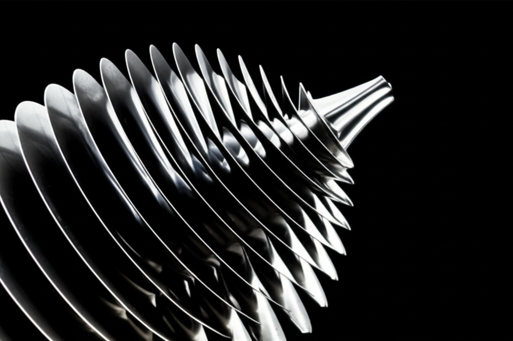
Stator vanes are non-rotating blades. They sit in rings or rows. They act like aerodynamic guides. They don’t spin yet they shape the flow in powerful ways. Think of them as the traffic cops of turbomachinery airflow. They don’t move traffic themselves. They direct it so everyone gets through faster and safer.
Where They’re Found
You’ll see stator vanes everywhere along the gas path of a jet engine:
- In the axial compressor between the spinning rotor blade rows
- At the compressor inlet as Inlet Guide Vanes (IGVs)
- At the compressor exit as outlet guide vanes or diffusers
- In the turbine as Nozzle Guide Vanes (NGVs) that feed the rotor with high-energy, well-aimed gas
Their Core Function
They do three big jobs:
- Convert kinetic energy into pressure in compressors for pressure recovery in diffusers
- Straighten or turn flow so rotor blades see the right angle of attack
- Accelerate and aim hot gas in turbines so the rotor can extract maximum work
How Stator Vanes Work: Mastering Airflow Direction and Energy Conversion
In Compressor Stages: Diffusing and Directing
Here’s the basic dance in a multi-stage axial compressor. A rotor adds swirl and kinetic energy to the air. The following stator vane row slows that air down and straightens it. Slower speed plus smooth turning means higher static pressure. That’s pressure rise. You repeat that stage by stage to reach the overall compressor pressure ratio.
The stators also prepare the air for the next rotor. They set the flow angle so the next rotor runs at a sweet angle of attack. That helps avoid flow separation on the rotor blades. It also reduces aerodynamic losses. In practical terms, well-designed stator vanes:
- Improve pressure recovery
- Remove swirl
- Set the proper incidence for the next stage
- Increase stage efficiency and keep the compressor away from the surge line
In Turbine Stages: Nozzle Guide Vanes
In the turbine, stator vanes get a different name. Nozzle Guide Vanes. They take very hot, high-pressure gas from the combustor. They accelerate it through shaped passages. Then they aim that jet at the turbine rotor blades at the correct angle. The rotor converts that directed, high-velocity gas into torque. Depending on design, a stage may lean more toward impulse or reaction. The NGV sets the split by shaping velocity and pressure drops. The hotter the gas and the better the aim, the more work the rotor can extract.
Types of Stator Vanes: Fixed vs. Variable Geometry
Fixed Stator Vanes
Many compressors and turbines use fixed vanes. You set their angle at design and you leave it. Fixed vanes suit simpler engines and compressors that live near a single operating point. They cost less. They weigh less. They can run well in steady industrial settings. The tradeoff shows up when conditions change. Fixed vanes can’t adapt to low-speed operations, off-design altitudes, or big throttle changes. Efficiency drops outside the design point. Surge margin can shrink near idle or during fast transients.
Variable Stator Vanes Explained
Variable Stator Vanes (VSVs) move. You can adjust their angle during operation. An engine can open them at low speed to keep airflow attached and stable. Then it can close them as speed rises to push efficiency. In many engines IGVs and early compressor stator rows are variable. The rest stay fixed.
Mechanically, VSVs share a ring or sector gear. Actuators push a unison ring. The ring twists knife-edge bushings or trunnions. Every vane rotates by a few degrees together. On modern engines a Full Authority Digital Engine Control (FADEC) commands the schedule. It takes speed, pressure, temperature, and throttle into account. Then it sets vane angles for surge protection and fuel burn. You might also see the term Electronic Engine Control (EEC) for earlier digital systems.
The benefits show up everywhere:
- Compressor stall prevention at low speeds and during throttle changes
- Wider operating range across altitude and temperature
- Better part-load efficiency and lower Specific Fuel Consumption
- Smoother transients with less risk near the surge line
Inlet and Outlet Guide Vanes
- IGVs sit at the very front of the compressor. They set the entry swirl and help avoid choke at high mass flow. They also protect surge margin at idle.
- Outlet guide vanes sit at the end of the compressor or fan. They straighten the flow and reduce swirl losses into the combustor or bypass duct.
Why Stator Vanes Are Indispensable: Critical Functions and Benefits
Maximizing Aerodynamic Efficiency
Every percentage point of efficiency matters. Stator vanes minimize turbulence and flow separation. They keep the boundary layer attached on vane surfaces. They deliver high pressure rise in compressors and solid power extraction in turbines. Well aligned flow means less loss and more useful work.
Preventing Compressor Stall and Surge
When I coached a new tech through an engine run after a heavy maintenance visit we watched the surge margin like hawks. VSV scheduling kept the operating point away from the surge line. That’s not a luxury. That’s life or death for the compressor. VSVs increase the stable operating range at low speed. They protect during takeoff, landing, and throttle sweeps. Surge can shock the compressor hard. Good vane control prevents it.
Optimizing Engine Performance and Fuel Economy
I’ve seen engines save meaningful fuel with smart vane schedules. Modern turbofans can reduce SFC by a few percent at off-design conditions with VSVs. That saves money and cuts emissions over thousands of flight hours. Stators help engines hit rated thrust with the least fuel. They do it by tuning flow angle, reducing losses, and raising compressor and turbine stage efficiency.
Adapting to Diverse Operating Conditions
From hot-and-high airports to cold mornings near sea level the engine needs flexibility. Air density changes. Speeds change. Loads change. Variable geometry handles these shifts without punishing efficiency. Fixed vanes can’t adapt which is why variable stator vanes show up in many high-performance engines.
Design and Aerodynamic Principles You Should Know
Vane Profile, Chord, Aspect Ratio
You’ll hear designers talk about vane profile or camber line. The shape sets how the vane turns the flow with minimal loss. Chord length matters because it affects diffusion rate and boundary-layer growth. Aspect ratio influences 3D effects and endwall losses. There’s no one-size-fits-all shape. Designers tailor profile, chord, and spacing to each stage’s duty.
Angle of Attack and Flow Turning
The vane’s incidence or effective angle of attack decides if flow stays attached. Turn the flow too fast and you invite separation. Turn it too little and you lose pressure recovery. Good stator design balances turning with diffusion and keeps a safe margin from stall on the vane surfaces.
Secondary Flows, Endwall Effects, and Tip Leakage
Real compressors and turbines live in an annulus with hub and casing endwalls. That geometry creates secondary flows. Corner vortices form near the hub and casing. They eat efficiency. Designers sculpt endwalls or add fillets to weaken those vortices. Tip gaps can leak flow around the vane or blade tips. That leakage also adds loss. You can tighten clearances and use abradable coatings to limit leakage in some sections.
Vane–Blade Interaction, Vane Pass Frequency, and Noise
Every time rotor blades pass a row of vanes the flow sees periodic disturbances. That sets a vane pass frequency. Poor spacing or mismatched profiles can create strong interaction tones. You hear it as blade–vane interaction noise. Careful profiling and spacing can shave a couple decibels off the noise footprint. That matters for community noise and for cabin comfort.
Materials, Manufacturing, and Maintenance
Advanced Materials and Coatings
- Compressor stator vanes often use titanium alloys or stainless steels. They need strength with low weight and good corrosion resistance. Titanium excels here especially in the front stages.
- Turbine NGVs see extreme gas temperatures. Advanced engines push turbine inlet temperatures that can exceed the melting point of the metal. NGVs use nickel or cobalt-based superalloys. They rely on internal cooling schemes and external coatings to survive. Ceramic Matrix Composites show promise in some hot sections for lower weight with heat tolerance.
- Thermal Barrier Coatings (TBCs) insulate the metal. They work with film cooling and internal passages to keep metal temperatures within limits.
- Abradable coatings can line casings near blade tips. They allow tight clearances with fewer rub penalties.
Manufacturing Methods
Manufacturers often use investment casting for complex NGV shapes. These castings can include internal cooling channels. You’ll see precision machining for sealing surfaces and mounts. Compressor stators may use forged or machined titanium or stainless parts. Even when you cast, you still need high-precision machining for airfoil surfaces and root fits. Surface finish on leading and trailing edges affects loss and durability.
Common Issues and Maintenance Practices
If you maintain engines long enough you’ll see the same patterns:
- Fouling and fouling-driven loss: Dust, oil mists, or salt deposits roughen airfoil surfaces. Even minor fouling can eat into efficiency and surge margin. Regular on-wing washes help.
- Erosion and Foreign Object Damage (FOD): Sand, ash, and runway grit sandblast leading edges. FOD can chip, dent, or bend vanes. Erosion rounds the profile and increases loss.
- Cracking and wear: Thermal cycling and vibration cause fatigue. You might see cracks at fillets, platforms, or mounts. VSV bushings wear and introduce slop which skews vane angles.
- Coating degradation: TBC spallation in hot sections leads to higher metal temperatures. That shortens life if you ignore it.
I always advocate scheduled inspections. Use boroscopes. Track trends. Tie findings to engine performance parameters like EGT margin, pressure ratios, and fuel flow. Tie maintenance to cycles or hours per OEM schedules. Non-destructive testing (NDT) helps catch cracks before they run. Dye penetrant and eddy current inspections show their value in overhaul shops. For hot-section NGVs, cooling passages need special attention during repair and overhaul. Plugged holes raise metal temperatures fast.
Field Data and What It Means
Over the years I’ve leaned on a few numbers to make the case for care:
- Variable stator vanes can reduce SFC by roughly 3–5 percent at part-load in modern turbofans. Small percentage big savings over an engine’s life.
- VSVs often expand the compressor’s stable operating range by about 15–20 percent at low speeds. That cushion reduces stall risk during takeoff and landing.
- Stators in an axial compressor stage can contribute roughly 20–30 percent of the stage’s total pressure rise through diffusion. They’re not passengers. They do real work.
- High-pressure turbine NGVs see gas temperatures that can reach the 1700°C range in advanced engines. Internal cooling and TBCs keep the metal safe.
- Light fouling or erosion can knock 1–2 percent off engine efficiency and trim 5–10 percent off surge margin. Don’t ignore minor deposits. They grow into major costs.
- Composite stators in cooler sections can cut weight by 20–30 percent vs metal parts. That helps thrust-to-weight and fuel burn.
Controls and Actuation: How VSVs Actually Move
Mechanical Linkages and Actuators
When I explain VSV mechanics I compare them to a synchronized umbrella. A unison ring wraps around the compressor case. Each vane has a lever arm tied to that ring. Hydraulic or electric actuators rotate the ring which rotates every vane in unison. You can segment the ring for thermal growth and assembly. You need low-friction bushings and careful alignment. If a bushing binds you’ll get uneven angles. Uneven angles trigger stalls or force the FADEC to pull back to protect the machine.
Electronic Engine Control and FADEC Scheduling
The FADEC or EEC schedules vane angles against a map. Inputs include spool speed, inlet temperature, ambient pressure, and throttle command. The schedule protects surge margin and improves part-load SFC. It also coordinates with variable bleed valves if the engine has them. Good control logic smooths transients and keeps airflow attached across the map. When troubleshooting a stall complaint I always check the VSV schedule and the actuator rigging first. The map doesn’t help if the hardware doesn’t follow the command.
Applications Beyond Jet Engines
Industrial Gas Turbines
Power plants and mechanical drives use gas turbines that mirror aero cores. They run at steady load more often which favors fixed vanes in some sections. Yet many still use IGVs or early-stage VSVs for start-up and part-load efficiency. The same aerodynamic principles apply. Control the flow. Maximize pressure recovery. Protect surge margin.
Turbochargers and Variable Nozzle Turbines
On turbochargers you’ll find variable nozzle turbines (VNT). The vanes change effective area to control turbine power across engine speed. That’s variable geometry in a compact package. It helps low-end torque and reduces turbo lag. The physics rhyme with aero engines. Turn and accelerate flow to hit the rotor with the right angle and speed.
Pumps and Fans
Large industrial fans and pumps also use guide vanes and diffusers. They straighten flow and convert kinetic energy into pressure. The blades and fluids differ yet the principles carry over. Turn the flow just enough. Avoid separation. Recover pressure efficiently.
Troubleshooting and Real-World Tips
A few lessons that saved me time and grief:
- If you see rising fuel flow for the same thrust or power, suspect fouling on stators and rotors. Schedule a wash and trend the result.
- If you get a low-speed rumble or faint surge puffs after maintenance, check VSV rigging and IGV angles. A degree or two out can push you toward the surge line.
- If the engine shows higher vibration after a sandstorm run, inspect leading edges on IGVs and early-stage stators for erosion. Minor blending can restore shape if limits allow.
- Watch actuator health. Sticky VSV actuators cause asymmetric vane angles. Asymmetry shows up as hot streaks or local stalls.
- For hot-section NGVs, monitor EGT margin trends. Falling margin with stable compressor health hints at NGV cooling or coating issues.
Future Directions: Adaptive and Smart Stator Vanes
Research keeps pushing into adaptive stator vane technology. I’m intrigued by smart vanes with embedded sensors that measure temperature or pressure. They could feed controllers in real time. You might see morphing or actively cooled designs that adjust shape within small limits. The goal is the same. Reduce loss. Expand operability. Cut emissions and noise without adding weight or complexity. It’s a tightrope walk yet progress continues.
Quick Terminology Note: “Stator Vanes” vs. “Stator Laminations”
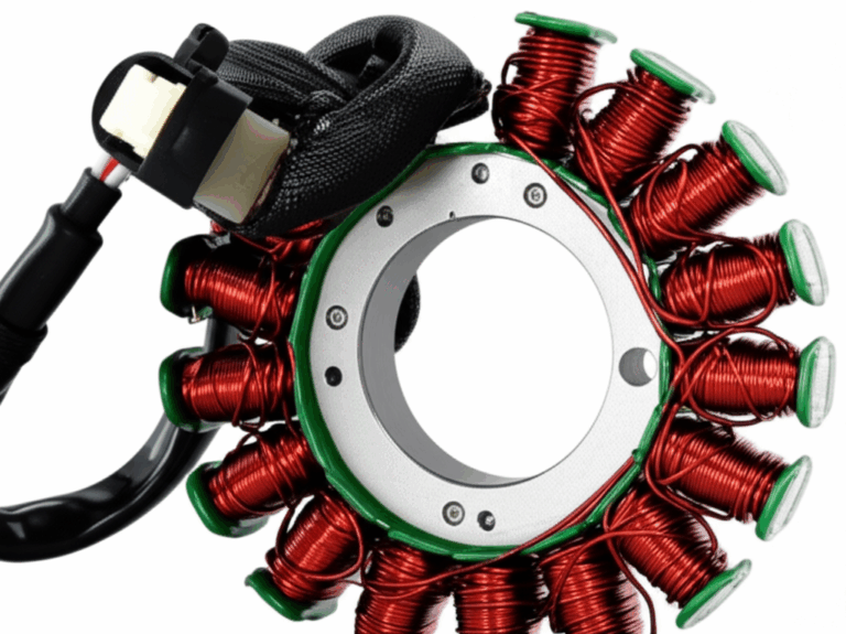
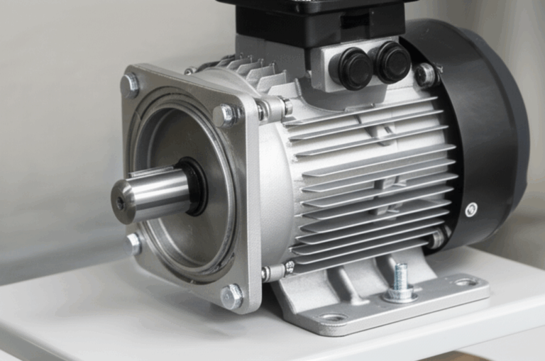
I get this question a lot. “Stator vanes” belong to turbomachinery and deal with airflow. “Stator laminations” belong to electric motors and transformers and deal with magnetic fields. Both use the word stator because both stay stationary. They are different worlds. If you’re researching electric machines you’ll bump into resources on laminations. For that topic you can explore the basics of stator core lamination, broader families of electrical steel laminations, and how the magnetic circuit pairs with a rotor core lamination. For clarity I’m focusing here on aerodynamic stator vanes in compressors and turbines.
Conclusion: The Silent Architects of Power and Efficiency
When I walk someone through a jet engine I pause at the stator rows. The rotors still grab attention because they spin and sparkle. The stators quietly make the magic possible. They turn raw velocity into pressure. They aim fire into useful work. They widen the safe operating range and trim fuel burn. They protect against stall and surge when conditions shift. They’re the silent architects behind thrust, power, and reliability.
From titanium compressor vanes to superalloy NGVs with thermal barrier coatings the engineering is remarkable. The controls are equally elegant. FADEC schedules variable stator vanes so the compressor stays happy in the rough patches. Maintenance keeps surfaces smooth and angles true. Small numbers like a 1–2 percent efficiency change or a few degrees of vane angle can decide your day. I’ve seen it play out in the field and in the data.
So what are stator vanes? They’re stationary airfoils with a dynamic purpose. They guide airflow with precision. They convert energy with grace. They keep complex machines stable and efficient across a wide map. Once you see what they do you won’t forget them. I didn’t. And I respect them more every time I hear an engine spool up smooth and strong.


