What Are Motor Lamination Stacks and Why Do They Matter for Performance?
Every design engineer faces the critical challenge of maximizing electric motor efficiency while managing complexity and production costs. If you’ve ever found yourself deep in the weeds, weighing the trade-offs between different lamination materials or wondering how a few micrometers of steel thickness could drastically alter a motor’s performance and thermal signature, you’re in the right place. The answers often lie within the motor’s core—specifically, in the design and construction of its lamination stack.
So, what exactly is a motor lamination stack?
Put simply, it’s the iron core of an electric motor, meticulously built from hundreds of thin, insulated steel sheets pressed together. Far from being a simple structural component, the lamination stack is the single most critical element for controlling energy loss. Its design directly dictates a motor’s efficiency, power output, heat generation, and ultimately, its real-world performance and reliability.
In This Article
- The Anatomy of a Motor Core: What is a Lamination Stack?
- The Direct Link: How Laminations Dictate Electric Motor Performance
- Lamination Design and Manufacturing: The Critical Trade-Offs
- Conclusion: The Unsung Foundation of Modern Electric Motors
- Frequently Asked Questions (FAQ)
The Anatomy of a Motor Core: What is a Lamination Stack?
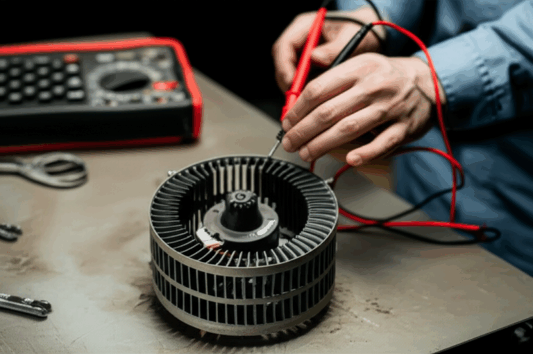
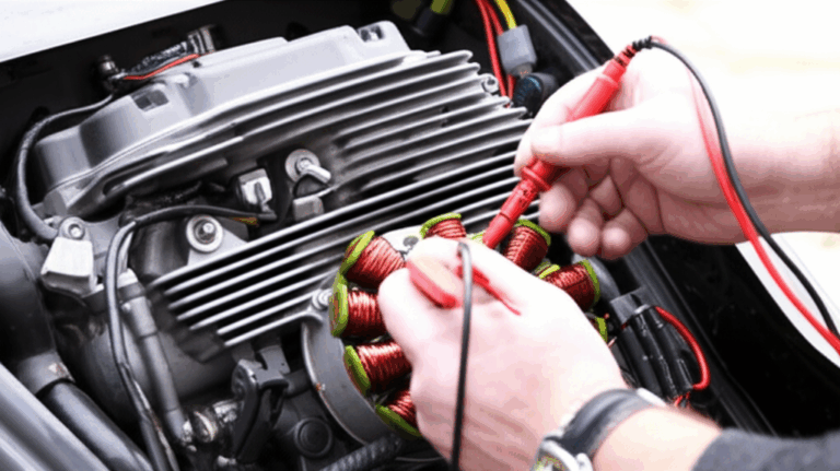
To truly grasp why laminations are so vital, you need to look inside the motor. The electromagnetic heart of nearly every modern electric motor—from the massive traction motors in an EV to the tiny brushless DC (BLDC) motors in a drone—is composed of a stator and a rotor. Both of these critical parts are built using lamination stacks.
Core Components: Stator and Rotor Stacks
The motor core consists of two main parts that interact to create rotation:
Both the stator and rotor are subjected to a rapidly changing magnetic field, and this is where the genius of laminations comes into play.
The “Why” Behind the Layers: Taming Eddy Currents
So, why not just use a solid block of iron for the motor core? It would certainly be cheaper and easier to manufacture.
The answer lies in a fundamental principle of electromagnetism described by Faraday’s Law of Induction. When a conductive material (like an iron core) is exposed to a changing magnetic field, small, localized electrical currents are induced within it. These are called eddy currents.
Think of eddy currents like unwanted whirlpools in a river of energy. In a solid iron core, these whirlpools would be huge, circulating freely and converting enormous amounts of electrical energy directly into useless heat. A motor with a solid core would overheat in seconds, wasting a massive percentage of its input power. It’s the electrical equivalent of driving with the emergency brake on.
This is the problem that motor laminations solve. By slicing the core into hundreds of thin, electrically isolated layers, you essentially build dams that break up the path of these currents. The large, energy-wasting whirlpools are chopped into thousands of tiny, insignificant ones that can’t gain momentum. This drastically reduces eddy current loss, which is one of the two major components of core loss.
Key Materials: From Standard Silicon Steel to Advanced Alloys
The material you choose for your laminations is a foundational design decision that impacts everything from cost to performance. While there are exotic options, the vast majority of electrical steel laminations are made from a few key material families.
- Silicon Steel (SiFe): This is the workhorse of the industry. Adding a small amount of silicon (typically 1-3%) to iron significantly increases its electrical resistivity, which further helps to reduce eddy currents. It offers a fantastic balance of magnetic performance (high magnetic permeability) and cost-effectiveness, making it the standard choice for industrial motors, HVAC systems, and consumer electronics. These materials are often referred to by their ASTM grades, such as M19 or M27.
- Thin Gauge Steels: As motors spin faster, the frequency of the magnetic field change increases. Since eddy current losses are proportional to the square of the frequency, they become a massive problem in high-speed applications. To combat this, engineers use thinner laminations. While a standard motor might use 0.5mm or 0.65mm thick steel, high-performance EV traction motors often use ultra-thin gauges of 0.35mm, 0.2mm, or even 0.1mm. This allows motors to operate efficiently at speeds exceeding 20,000 RPM.
- Cobalt-Iron Alloys (CoFe): For the most demanding applications where power density and performance at high temperatures are non-negotiable—think aerospace actuators or motorsports—engineers turn to materials like Hiperco. These cobalt-iron alloys offer a much higher magnetic saturation point. This means they can handle a stronger magnetic field before becoming “full,” which directly translates to higher torque density. You can get more power out of a smaller package, but this performance comes at a significantly higher cost.
- Amorphous Metals: Materials like Metglas are non-crystalline, meaning they lack the grain structure of traditional steels. This unique property dramatically reduces hysteresis loss (the other major type of core loss), making them incredibly efficient, especially in high-frequency applications like transformers.
The Unseen Hero: The Role of Insulation Coating
The entire concept of a lamination stack falls apart if the individual layers can touch each other electrically. A single short circuit between laminations can create a path for eddy currents, undoing the benefit of the layered design.
That’s why each individual lamination is coated with a very thin, durable layer of insulation. This dielectric coating, often an organic enamel referred to by standards like C5, is only a few microns thick but is essential for electrically isolating each sheet. It must withstand the pressure of stacking, the heat of the annealing process, and the operational temperatures of the motor for its entire service life. Without this unseen hero, the efficiency gains from lamination would be lost.
The Direct Link: How Laminations Dictate Electric Motor Performance
The design of the lamination stack isn’t just an academic exercise in physics; it has direct, measurable consequences on the performance metrics you care about. From the range of an electric vehicle to the electricity bill of a factory, the quality of the motor core is paramount.
1. Minimizing Core Losses (Eddy Currents & Hysteresis)
Core loss, also known as iron loss, is the energy wasted as heat within the motor’s stator and rotor stacks. It’s the primary enemy of efficiency and is composed of two main culprits that laminations are designed to fight:
- Eddy Current Loss: As we’ve covered, this is energy lost to unwanted electrical currents in the core. The single most effective way to fight it is by using thinner laminations. As a rule of thumb, halving the lamination thickness can reduce eddy current losses by up to 75%. This is why high-frequency motor design for applications like EVs is impossible without ultra-thin gauge electrical steel.
- Hysteresis Loss: Think of this as “magnetic friction.” Every time the magnetic field reverses—which happens thousands of times per second in a running motor—the magnetic domains within the steel have to flip their orientation. This process isn’t perfectly efficient; it takes energy to overcome the material’s internal resistance to this change, known as coercivity. This lost energy is released as heat. Material selection is key here. High-grade non-oriented electrical steels and advanced alloys are engineered to have lower hysteresis loss, making them easier to magnetize and demagnetize.
2. Maximizing Efficiency and Power Density
Every watt of energy lost to heat in the core is a watt that doesn’t become useful mechanical work at the shaft. By minimizing core losses through smart material selection and lamination design, you directly boost the motor’s efficiency.
Consider the real-world impact. In an EV, a 2-3% improvement in motor efficiency can translate to several extra miles of range—a huge competitive advantage. In an industrial setting, a factory running hundreds of high-efficiency motors can save thousands of dollars on energy costs annually.
This efficiency gain also leads to higher power density and torque density. Because a motor with a low-loss core generates less waste heat, you can push more current through its windings to get more power out of a given frame size. This allows you to design smaller, lighter motors that deliver the same performance, a critical factor in weight-sensitive applications like EVs, drones, and portable power tools.
3. Improving Thermal Management
Heat is the silent killer of electric motors. Excessive temperatures can degrade the insulation on the copper windings and, even more critically, permanently demagnetize the expensive rare-earth magnets used in high-performance PMSM motors.
A well-designed lamination stack is the first line of defense in thermal management. By generating less core loss in the first place, you reduce the thermal load on the entire system. This has several cascading benefits:
- Simpler Cooling Systems: A motor that runs cooler may not need a complex liquid cooling jacket, relying instead on simpler air cooling. This reduces cost, weight, and complexity.
- Improved Reliability: Lower operating temperatures lead to a longer service life for all motor components, from bearings to insulation.
- Sustained Peak Performance: Motors often have to be “de-rated” during continuous operation to avoid overheating. A low-loss core allows a motor to sustain its peak power and torque for longer periods.
4. Enhancing Torque and Speed
The torque of an electric motor is directly related to the strength of its magnetic field, or magnetic flux density. High-performance lamination materials, like high-grade silicon steel or cobalt-iron alloys, have a high magnetic permeability and saturation point. This means they can channel more magnetic flux before becoming saturated, enabling the design of motors with incredibly high torque.
Furthermore, low-loss laminations are the key to unlocking high-speed operation. As rotational speed increases, so does the frequency of the magnetic field reversals. In a motor with a poor-quality core, core losses would skyrocket at high speeds, generating catastrophic amounts of heat. By using ultra-thin, low-hysteresis laminations, engineers at companies like Tesla and Siemens can design motors that operate efficiently and reliably at speeds well above what was possible just a decade ago.
Lamination Design and Manufacturing: The Critical Trade-Offs
Choosing the right material is only half the battle. How those laminations are manufactured and assembled into a core has a profound impact on the final performance of the motor. Here, engineers must navigate a series of critical trade-offs between performance, cost, and manufacturability.
Lamination Thickness: The Balance Between Performance and Cost
This is perhaps the most fundamental trade-off in motor core design.
- Thinner is Better (for Performance): As established, thinner laminations are champions at reducing eddy current loss, making them essential for high-frequency, high-efficiency motors. A switch from standard 0.5mm steel to 0.2mm steel can reduce eddy current losses by over 75% in a high-speed motor.
- Thicker is Cheaper (for Manufacturing): Thinner steel is more expensive to produce. It’s also more difficult to handle and stamp without causing defects. Stacking a core requires more individual laminations, increasing assembly time and complexity.
Therefore, the choice depends entirely on the application. For a standard 60 Hz industrial motor, thicker laminations (0.5mm to 0.65mm) provide perfectly adequate performance at a low cost. For an EV traction motor spinning at 400 Hz (equivalent to 24,000 RPM for a 2-pole motor), the performance penalty of thick laminations would be unacceptable, making ultra-thin gauges a necessity despite the higher cost.
Manufacturing Methods: Stamping vs. Laser Cutting
Once you’ve chosen your material, you need to cut it into the precise shape of your stator or rotor lamination.
- Stamping: This is the go-to method for mass production. A high-speed press uses a hardened steel die to punch out lamination shapes from a roll of electrical steel. It’s incredibly fast and cost-effective for high volumes. However, the mechanical shearing action can induce stress and create small burrs on the edges of the lamination. This stress can degrade the material’s magnetic properties, increasing hysteresis loss by 5-15%. An annealing (heat treatment) process is often required after stamping to relieve this stress.
- Laser Cutting: This method uses a high-power laser to cut the lamination shape without any mechanical contact. It’s ideal for prototyping and low-volume production because it doesn’t require expensive custom tooling. More importantly, it induces virtually no mechanical stress on the material, preserving its optimal magnetic properties right out of the machine. It’s also perfect for complex geometries, such as those used in axial flux motors. The downside is that it’s a much slower and more expensive process per part compared to stamping.
Assembly: The Importance of the Stacking Factor
After the laminations are cut, they must be assembled into a rigid core. How this is done affects both mechanical integrity and electromagnetic performance. The key metric here is the stacking factor, which is the ratio of the volume of iron to the total volume of the core. A higher stacking factor (typically 95-98%) means the core is more densely packed with steel, leading to a more powerful magnetic circuit.
Two common assembly techniques are:
- Welding: A fast and strong method where beads of weld are run along the outside of the stack to hold it together. While cost-effective, the heat from welding can damage the insulation between laminations near the weld, creating localized short circuits that can increase eddy current losses.
- Bonding or Interlocking: Advanced methods involve applying an adhesive that bonds the laminations together as they are stacked or using interlocking features stamped into the laminations themselves. Bonding provides excellent insulation between every layer, minimizing interlaminar losses and improving the core’s structural rigidity and heat transfer capabilities. For high-performance motors, a switch from welding to bonding can reduce total core losses by 2-5%, a significant gain when every watt counts.
Conclusion: The Unsung Foundation of Modern Electric Motors
Motor lamination stacks are far more than simple structural supports; they are active, highly engineered electromagnetic components that form the very foundation of an electric motor’s performance.
The choices you make in their design reverberate through every aspect of the final product.
- Material Selection dictates the ceiling for magnetic performance and sets the baseline for core losses.
- Lamination Thickness is your primary weapon against eddy currents and a key enabler of high-speed operation.
- Insulation Coating is the invisible shield that makes the entire layered strategy possible.
- Manufacturing and Assembly Methods determine how much of the material’s potential is realized in the final core.
Understanding these interconnected principles empowers you to have more productive conversations with suppliers and make informed design decisions. By carefully engineering the lamination stack, you directly control the efficiency, power, thermal stability, and reliability of every motor you design, from the simplest industrial automation solution to the most advanced E-mobility powertrain.
FAQ
Q: Why can’t you use a solid block of iron for a motor core?
A: A solid iron core exposed to a motor’s rapidly changing magnetic field would act like a short-circuited conductor. This would induce massive, uncontrolled electrical currents called eddy currents, which would convert a huge amount of energy into waste heat, causing the motor to fail almost instantly from overheating and extreme inefficiency.
Q: How much more efficient is a motor with thin laminations?
A: The efficiency gain is significant, especially at high speeds. For example, switching from a standard 0.5mm lamination to an ultra-thin 0.2mm lamination can reduce eddy current losses by over 75% in a high-frequency motor. This can translate to a total motor efficiency improvement of several percentage points, which is a critical gain in applications like electric vehicles.
Q: What is the difference between stator and rotor laminations?
A: Both are made of stacked, insulated steel sheets. The primary difference is their function and geometry. Stator laminations are stationary and have slots for the copper windings that create the magnetic field. Rotor laminations rotate and are designed to interact with that field to produce torque; they may have features for mounting permanent magnets or conductive bars.
Q: What is a “stacking factor” and why is it important?
A: The stacking factor is the ratio of the height of the magnetic steel in a core to the total stack height (which includes the insulation layers and any air gaps). A higher stacking factor (e.g., 97%) means the core is more densely packed with steel. This is important because it creates a more effective path for the magnetic flux, leading to a more powerful and efficient motor for a given size.