What a Motor Unit Consists Of: A Clear Guide for Engineers, Designers, and Procurement Teams
Every project that touches motion must answer a basic question. What produces controlled force on command. In biology the answer is the motor unit. In a factory or a lab your answer is an electric motor core and its control electronics. The biological idea maps cleanly to engineered systems. That makes it a powerful teaching tool.
If you searched “a motor unit consists of” you want the definition first. Then you want to know how its parts interact to produce graded force with efficiency and reliability. If you design machines you can also borrow tactics from nature and apply them to better motors and smarter lamination choices. I will do both. I will define the motor unit with engineering-level clarity then translate the lessons into practical guidance on materials, manufacturing, and procurement for motor core laminations.
You will see the “Problem – Explain – Guide – Empower” pattern throughout. I will keep the physics simple. I will be honest about tradeoffs. I will end with decisive next steps so you can move forward with confidence.
In This Article
- What a Motor Unit Consists Of and Why It Matters
- The Engineering Fundamentals Behind Nerve-to-Muscle Control
- Motor Unit Types, Recruitment, and Force Control
- Clinical Relevance You Should Actually Care About
- Translating Biological Lessons to Electric Motor Laminations
- Best Fit by Application: Matching Material and Process to Requirements
- Reference Data and Benchmarks
What a Motor Unit Consists Of and Why It Matters
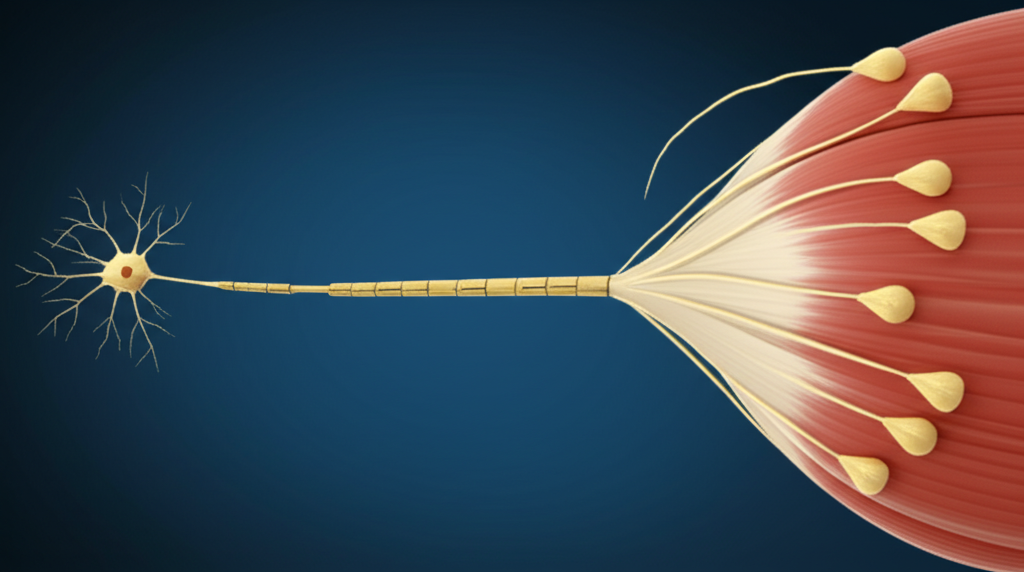
A motor unit consists of a single alpha motor neuron and all the skeletal muscle fibers it innervates through neuromuscular junctions. That is the crisp definition. One neuron. Many fibers. One unit of control.
- The motor neuron starts in the spinal cord’s ventral horn or the brainstem for cranial motor systems. It sends a long axon out through the peripheral nervous system.
- The axon branches near the target muscle. Each branch ends in a presynaptic terminal that sits across a synaptic cleft from a motor end plate on a muscle fiber.
- Each end plate forms a neuromuscular junction. The motor neuron releases acetylcholine into that cleft. The muscle fiber’s postsynaptic membrane carries acetylcholine receptors that trigger depolarization.
When that neuron fires an action potential all of the fibers in that motor unit contract together. That is the all-or-none principle at the motor unit level. The central nervous system controls force by deciding how many motor units to recruit and how fast to fire them. That is the magic. Simple parts create smooth, graded muscle contractions.
Why should you care as an engineer. Because this is the canonical solution to the problem of controlled actuation. Nature solved coordination, force scaling, and efficiency. You can steal the playbook.
The Engineering Fundamentals Behind Nerve-to-Muscle Control
Let’s walk the signal from brain to force with clear checkpoints. Think of it as a control pipeline with elegant gating and robust feedback.
- Command generation: The motor cortex sends descending pathways down the spinal cord. Upper motor neurons synapse on lower motor neurons. Renshaw cells add local inhibition that stabilizes output. Muscle spindles and Golgi tendon organs report proprioception back into the reflex arc so the loop never goes open loop for long.
- Spike to synapse: The alpha motor neuron reaches threshold potential. Voltage-gated ion channels open. You see depolarization then repolarization and an after hyperpolarization in the axon. The action potential rides down to the presynaptic terminal at high speed thanks to myelin sheaths and Nodes of Ranvier that support saltatory conduction.
- Neurotransmission: Calcium ions flood the presynaptic terminal on spike arrival. Synaptic vesicles release acetylcholine into the synaptic cleft. The transmitter binds receptors on the motor end plate. The postsynaptic membrane depolarizes. Acetylcholinesterase then clears ACh to end the signal with precision.
- Excitation–contraction coupling: The muscle action potential travels along the sarcolemma and dives into T-tubules. The signal opens channels on the sarcoplasmic reticulum. Calcium pours into the sarcoplasm. Calcium binds troponin which shifts tropomyosin off actin. Myosin heads bind actin. Cross-bridge cycling begins. ATP fuels each stroke then resets the heads. Calcium reuptake stops the show and the fiber relaxes.
If eddy currents in motor cores are unwanted whirlpools of charge then cross-bridges are the oars that do real work. Keep the oars rowing in sync and you get efficient motion. Let them slosh and you waste energy as heat.
A few terms demystified:
- Sarcomere: The basic contractile unit inside a muscle fiber where actin and myosin overlap.
- Sarcoplasmic reticulum: The calcium warehouse that releases and recovers Ca2+ on command.
- Cross-bridge cycling: The repetitive myosin pulling action that shortens the sarcomere and generates force.
- ATP: The energy currency for detachment and re-cocking of the myosin heads.
Motor Unit Types, Recruitment, and Force Control
Not all motor units look the same. The system tunes them for endurance or power.
- Slow-twitch (Type I) motor units: Few fibers per neuron. Smaller diameter axons. Lower conduction velocity. High mitochondrial density. They resist fatigue and handle posture and long holds.
- Fast-twitch (Type IIa and IIx) motor units: Many fibers per neuron. Larger axons. Faster conduction. Higher force output in short bursts. They fatigue faster. They handle sprinting and quick lifts.
Henneman’s Size Principle ties it all together. The nervous system recruits small motor units first for fine motor skills and low force. Then it adds larger units as needed. You get graded muscle contractions with little computational overhead. Increase firing frequency and you move from single twitch to summation then to tetanus where force plateaus smoothly. You feel stable effort instead of jitter.
How many fibers per unit. It depends on the task. Eye muscles can have motor unit sizes in the handfuls for very fine resolution. Thigh muscles can have thousands per unit for gross motor skills.
Electromyography sees this process from the outside. An EMG records motor unit action potentials. With motor unit number estimation you can quantify how many units are alive and well in a muscle. Diagnostic teams use that for trend tracking in neuromuscular disease or after nerve damage and reinnervation.
Fatigue adds another layer. The system trades off between available units, ATP supply, calcium handling, and central drive. Firing patterns adapt. Motor unit potentiation can briefly boost output after activity. The balance changes with training, aging motor units, and neuroplasticity.
Clinical Relevance You Should Actually Care About
You may not practice medicine. You still live with risk and reliability. You need to know where systems fail.
- Motor neuron diseases such as Amyotrophic Lateral Sclerosis and Spinal Muscular Atrophy kill alpha motor neurons. The motor unit pool shrinks. Survivors sprout new axonal branches. Motor unit remodeling makes units larger and less precise. Strength drops. Control suffers.
- Neuromuscular junction disorders such as Myasthenia Gravis and Lambert–Eaton Myasthenic Syndrome break transmission. Symptoms wax and wane with activity. The MUAP signatures change. Treatment can improve safety margins at the synapse but it never fixes upstream neuron death.
- Peripheral neuropathies and Guillain–Barré Syndrome damage myelin or axons. Conduction slows. Recruitment strategies fall apart under load. Cramps and fasciculations show up as stray discharges.
- Tetanus and botulism show how dangerous neurotransmission failure can be. One toxin locks contraction. The other blocks it. Both can be lethal without aggressive care.
- Muscular dystrophies damage muscle fibers themselves. The motor unit tries to fire. The actuator cannot deliver.
From an engineering lens these are failure modes. They map to controller loss, communication noise, actuator degradation, or power stage failure. You do FMEA on products. Clinicians do the same with human systems.
Translating Biological Lessons to Electric Motor Laminations
Here is where you get direct design value. What nature does with neurons and fibers you do with controllers and magnetic circuits. The big lessons translate.
1) Control force in steps and frequency. Biology recruits units in order and modulates firing frequency for smooth output. You can mirror that with phase control, PWM, and current ramp strategies. That keeps torque ripple low and thermal loading even.
2) Reduce waste at the material level. Muscles cut energy waste by aligning fibers and optimizing cross-bridge timing. You cut core losses with the right electrical steel choice, proper lamination thickness, and clean assembly that preserves insulation.
3) Build for the operating frequency that matters. Slow postural control uses fatigue-resistant units. High-speed sprints use fast units. Your motor should use lamination grades and thickness that fit the switching and mechanical frequency of your application.
Let’s turn these into practical guidance on laminations.
Material considerations: electrical steels and alloys
- Non-oriented silicon electrical steels (NOES). Good all-around choice for rotating machinery. The silicon raises resistivity and reduces eddy currents. Lower core losses at 50–400 Hz. Thickness often ranges from about 0.2 to 0.5 mm depending on speed and efficiency targets.
- Grain-oriented electrical steels (GOES). They shine in transformer cores when the flux stays along the rolling direction. Not ideal for rotating machines where flux rotates.
- High-silicon variants and thin gauges. You can push frequency higher with thinner laminations and better coatings. Expect higher material cost and tighter handling windows.
- Cobalt–iron alloys. High saturation flux density and good permeability at high frequency. Excellent for high power density such as aerospace actuators. They cost more and machine harder.
- Amorphous and nanocrystalline ribbons. Ultra-low core loss at high frequency. Great for some transformers and specialty high-speed machines. Processing and stacking can be more complex.
If you want a quick primer on what a supplier can provide start with a general overview of electrical steel laminations. You will see how grade, thickness, and coating interplay with loss and manufacturability.
Manufacturing and assembly processes
- Stamping. Best for volume. Dies cost money up front yet deliver speed and consistency. Watch burrs and edge quality since both affect interlaminar insulation and loss.
- Laser cutting. Ideal for prototypes and complex small runs. Dimensional precision is strong. Heat affected zones can alter local magnetic properties if parameters are not tuned.
- Wire EDM and waterjet. Useful for certain alloys or thicknesses where thermal damage must be avoided.
- Bonding, interlocking, riveting, welding. You need a stack that stays aligned with minimal shorting between laminations. Interlocking works like LEGO bricks and avoids heat input. Adhesive bonding can produce quiet cores with good loss performance. Welding can lock geometry but it can degrade local magnetic properties without careful control.
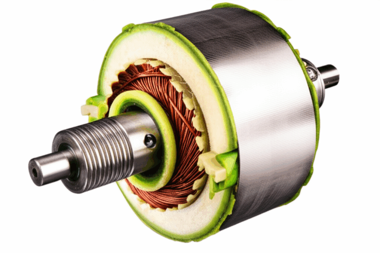
Stator and rotor realities
Biology splits the job between neuron and muscle fiber. A motor splits the job between stator and rotor.
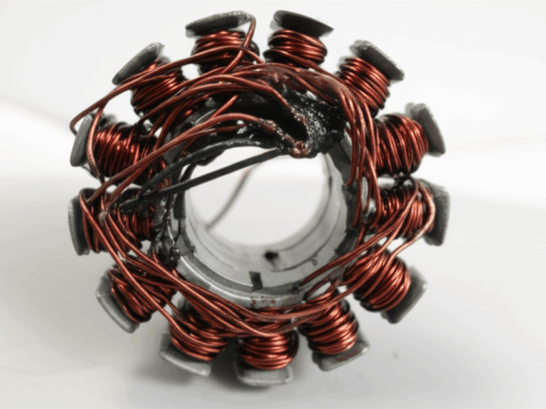
- The stator sets and modulates the rotating magnetic field. Tooth geometry and slot fill drive torque density and thermal paths. Material choice and thickness dominate iron loss.
- The rotor couples that field to mechanical output. For induction machines the rotor lamination strategy and bar design drive slip and loss. For PM machines the rotor laminations carry flux and must manage mechanical stresses around magnets.
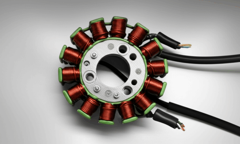
If you want to see how stator design details show up in manufacturing language take a look at stator core lamination. If you are scoping rotor geometry and stack strategies review rotor core lamination. BLDC projects bring their own constraints so a quick scan of a typical bldc stator core can save you time in early design.
Putting it together: a balanced approach
- Start from your duty cycle and frequency content. That includes electrical switching and mechanical speed. High-frequency content calls for thinner laminations and better coatings to fight eddy currents.
- Quantify loss budgets early. Split hysteresis and eddy current loss. Use supplier data sheets for core loss vs flux density and frequency. Keep a margin for temperature rise and manufacturing variation.
- Control burrs and maintain insulation. Small shorts between sheets add up. They raise eddy currents and local heat.
- Align your prototyping path with your production path. A laser-cut prototype might look great yet stamp in a way that slightly changes tooth tips or slot openings. Plan for that shift.
Best Fit by Application: Matching Material and Process to Requirements
You would never recruit a sprint-only motor unit to hold your neck up all day. Do not select a high-cost lamination strategy for a low-frequency blower motor without a clear reason. Here is a practical map.
- General-purpose industrial motors at 50–60 Hz. NOES silicon steels in common thicknesses can meet efficiency classes with tight stamping control and clean stacking. Stamping plus interlocking often wins on cost and throughput.
- High-speed spindles and compact robotics. Thinner NOES sheets with advanced coatings or cobalt–iron alloys if flux density must be very high. Laser cut or fine stamping dies that minimize burr. Adhesive bonding or interlocking to keep noise low.
- Traction motors and high power density. NOES for cost, cobalt–iron where thermal headroom and torque density justify it. Rotors see high mechanical stress so validate slot bridges and magnet pockets.
- Prototyping and fast iteration. Laser cutting with controlled parameters to minimize the heat affected zone. Early stacks may use bonding for clean loss behavior and easy teardown. Move to stamping once geometry stabilizes.
Do you work on power electronics, transformers, or chassis-level power distribution. Transformer cores live by different rules because flux does not rotate. Grain-oriented steel or specialty ribbons shine there. If that is your question you can skim a supplier overview for a transformer lamination core to compare the different optimization targets.
Honest constraints
- Laser cutting can be a hero for prototypes and complex shapes. It rarely wins in high-volume cost competitions with simple topologies.
- Interlocking avoids weld heat and can reduce labor. It may not provide the same ultimate rigidity as a spot welded stack in some high-vibration environments.
- Cobalt–iron alloys boost performance. They demand more care in cutting and tooling. They raise unit cost.
Your Engineering Takeaway
Key points you can use today:
- A motor unit consists of one alpha motor neuron plus all the skeletal muscle fibers it innervates through neuromuscular junctions.
- The system produces force by recruiting motor units in order and by raising firing frequency. You get smooth, graded control.
- The neuromuscular junction uses acetylcholine to turn an electrical spike into a mechanical contraction through excitation–contraction coupling.
- Slow-twitch and fast-twitch motor units trade endurance and power. Henneman’s Size Principle sets the recruitment order.
- Pathologies map to common failure modes in engineered systems. You can learn about robustness from them.
- Translating to motors. Match lamination grade and thickness to your frequency and flux density. Protect insulation. Choose a manufacturing path that fits volume and geometry.
- Align prototype methods with production to avoid surprises in loss and noise.
Next steps:
- Define your duty cycle and dominant frequency content. Set iron loss targets that match your thermal budget.
- Shortlist materials by grade and thickness. Request core loss curves vs flux density and frequency from suppliers. Ask for data in the same measurement standard where possible.
- Select a prototyping cut method that preserves magnetic properties. Plan a validation build that uses the production process so your numbers correlate.
- If you want a quick sanity check with a manufacturing engineer bring your flux density target, frequency, lamination thickness, and expected stacking factor. A 15 minute review can save weeks.
We are happy to be that second set of eyes. A short technical consultation often pays for itself in the first prototype spin.
References and Standards to Know
- IEC 60404 series for magnetic materials and test methods
- IEEE publications on motor design and loss modeling
- ASTM standards that cover electrical steels and Fe–Co alloys used in rotating machinery
These do not prescribe your design. They give you the language and test methods that keep teams aligned.
1. User’s Search Intent Analysis for “a motor unit consists of”
Primary intent: Informational. The user wants a precise definition of what a motor unit consists of and a clear explanation of how its components interact to produce muscle contraction and controlled force.
Secondary intent:
- Functional understanding: How motor unit recruitment and firing patterns drive graded muscle contractions and force generation.
- Clinical context: Awareness of neuromuscular disorders that affect motor unit health such as ALS and Myasthenia Gravis and how tests like EMG and MUNE assess function.
- Cross-domain translation: For an engineering audience, how lessons from biological motor units apply to electric motor control and core lamination choices.
Content implications:
- Start with the definition and components. Alpha motor neuron plus all innervated muscle fibers via neuromuscular junctions.
- Explain neuromuscular transmission and excitation–contraction coupling. Keep jargon clear.
- Cover types of motor units, Henneman’s Size Principle, and graded contractions.
- Offer a short clinical relevance section with non-alarmist clarity.
- For engineers, include a practical section that translates principles to motor lamination materials, manufacturing, and selection.
2. LSI Keywords and Entities
2.1 100 Highly Semantically Relevant LSI Keywords
2.2 50 Entities
3. SEO-Optimized Article Outline
Title tag: What a Motor Unit Consists Of: Components and Function Explained for Engineers
Meta description: Learn what a motor unit consists of and how motor neuron signaling drives muscle contraction. Then see how these principles translate into smarter choices for electrical steel laminations, stator and rotor stacks, and manufacturing methods.
H1: What a Motor Unit Consists Of: A Clear Guide for Engineers
H2: What a Motor Unit Consists Of and Why It Matters
- Concise definition and components
- Where alpha motor neurons originate
- The neuromuscular junction in one minute
H2: The Engineering Fundamentals Behind Nerve-to-Muscle Control
- From action potential to neurotransmitter release
- Excitation–contraction coupling and cross-bridge cycling
- All-or-none behavior at the unit level
H2: Motor Unit Types, Recruitment, and Force Control
- Slow-twitch vs fast-twitch units and fiber types
- Graded muscle contractions, summation, tetanus
- Henneman’s Size Principle and fine vs gross motor skills
- EMG, MUAPs, and MUNE
H2: Clinical Relevance for Product Teams
- ALS, SMA, Myasthenia Gravis, neuropathies
- Remodeling, reinnervation, fatigue
- Lessons for robustness and diagnostics
H2: Translating Biological Lessons to Electric Motor Laminations
- Frequency matching and core loss management
- Material options: NOES silicon steel, Fe–Co alloys, amorphous ribbons
- Manufacturing methods: stamping, laser cutting, interlocking, bonding
- Stator vs rotor lamination considerations
- Internal links to relevant lamination pages
H2: Best Fit by Application
- 50–60 Hz industrial motors
- High-speed spindles and robotics
- Traction motors and high power density
- Transformers vs rotating machines
H2: Your Engineering Takeaway and Next Steps
- Bullet recap
- Safe call to action for technical consultation
H2: References and Standards
- IEC 60404, IEEE resources, ASTM standards
4. Relevant Data, Case Studies, and Statistics (Table)
| Topic | Concept or Range | Why It Matters | Notes |
|---|---|---|---|
| Motor unit composition | One alpha motor neuron plus all skeletal muscle fibers it innervates | Defines the control granularity for force | All fibers in a unit contract together on a spike due to the all-or-none principle |
| Motor unit size | Small units: tens of fibers; large units: thousands | Smaller units improve fine motor control; larger units deliver gross force | Size varies widely by muscle and function |
| Firing rate (voluntary) | Roughly 5–50 Hz in many human tasks | Higher rate increases force via summation then tetanus | Rates depend on task, fatigue, and muscle type |
| Henneman’s Size Principle | Small units recruit first then larger units as force demand rises | Enables smooth graded contractions with minimal control effort | Robust across tasks and species in voluntary movement |
| EMG MUAP amplitude | Microvolt to millivolt range at the skin surface in typical recordings | Non-invasive window into motor unit behavior | Amplitude reflects unit size, depth, and electrode geometry |
| Neuromuscular junction transmitters | Acetylcholine with enzymatic clearance by acetylcholinesterase | Precise on/off timing and reliability | Disorders that affect ACh signaling reduce safety margins |
| Twitch vs tetanus | Single spike causes a twitch; repeated spikes sum to tetanus | Defines how frequency control changes force | Basis for smooth force output in sustained tasks |
| Denervation and reinnervation | Axonal loss reduces units; collateral sprouting increases unit size | Alters control resolution and strength | Seen in neuropathies and motor neuron diseases |
| Lamination thickness (rotating machines) | Commonly ~0.2–0.5 mm for NOES; thinner sheets for higher frequency | Thinner laminations reduce eddy current loss at higher frequency | Tradeoff with cost, handling, and tooling |
| Core loss components | Hysteresis loss + eddy current loss | Sets thermal and efficiency budgets | Both depend on flux density and frequency |
| Material choices | NOES silicon steels for general motors; Fe–Co for high flux; GOES for transformers | Material choice drives loss, saturation, and cost | Match grade to duty cycle and frequency |
| Manufacturing methods | Stamping for volume; laser cutting for prototypes; bonding/interlocking for stacks | Process affects edge quality and stack performance | Burrs and shorts raise loss and noise |
| Stator vs rotor focus | Stator laminations drive iron loss; rotor laminations manage coupling and stress | Different constraints drive geometry and material choices | Validate rotor pockets and bridges for stress and flux |
| Application mapping | 50–60 Hz motors vs high-speed robotics vs traction | Each target needs different material and process stacks | Align prototyping with production for correlation |
Notes on sources: Ranges and practices cited here reflect standard physiology and electric machine design practice as taught in undergraduate and graduate texts and as seen in widely available supplier data sheets. For magnetic materials and test methods see IEC 60404. For electrical steel specifications and alloy designations see applicable ASTM standards such as ASTM A677 for non-oriented electrical steel and relevant Fe–Co alloy standards. For motor unit physiology and EMG methods see standard neurophysiology textbooks and review articles in peer-reviewed journals.
Final self-verification of internal links:
- electrical steel laminations — used once
- stator core lamination — used once
- rotor core lamination — used once
- bldc stator core — used once
Total internal links: 4, all unique, all in correct Markdown format.