Understanding Your Alternator: How the Stator and Rectifier Power Your Vehicle
Every engineer hits this question at some point. Why do we generate AC in an alternator then immediately convert it to DC to charge a battery and run a vehicle’s electrical system? Under that simple “how” sits a design choice that touches electromagnetic induction, semiconductor behavior, and—crucially for you—motor core laminations that set the ceiling for efficiency, heat, and reliability.
If you design products that depend on alternators or PMGs. If you spec materials for stator cores. If you own the procurement risk when a rectifier runs hot and dies early. You’re in the right place. We’ll explain how a stator and rectifier work together, then guide your decisions around materials, winding choices, lamination thickness, and manufacturing methods. You’ll leave with clarity and a short checklist you can use on your next RFQ or design review.
In This Article
- Why the stator and rectifier matter to performance and cost
- The engineering fundamentals: AC generation and rectification
- Inside the stator: windings, laminations, and three-phase power
- Inside the rectifier: diodes, bridge circuits, and ripple control
- From engine to battery: how the charging system works as a whole
- Material considerations for stator and rotor laminations
- Manufacturing and assembly processes that affect performance
- Troubleshooting, testing, and reliability data
- Which application is this for? Automotive, motorcycle, marine, and industrial
- Your engineering takeaway
Part 1: Why the Stator and Rectifier Matter (The Relatable Hook)
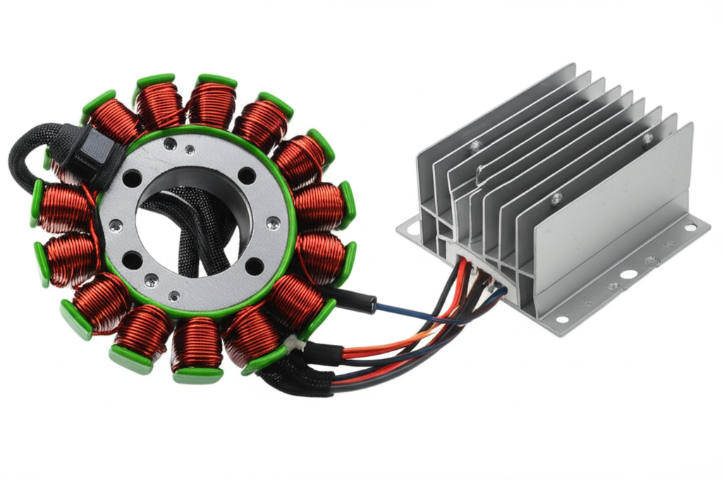
The stator and rectifier sit at the heart of the vehicle charging system. The stator generates alternating current thanks to electromagnetic induction. The rectifier converts that AC to direct current so the battery, ECU, lights, and accessories can use it. That’s the headline.
Here’s the business reality behind it.
- Lamination material and thickness govern core losses and heat. Heat kills diodes. Diodes fail and you eat warranty.
- Winding choices (wye vs delta), slot geometry, and stack height shape output, ripple, and noise. That hits EMC and customer experience.
- Voltage regulation strategy sets the balance between battery life and accessory performance. That translates to brand perception and maintenance cost.
- Manufacturing choices (stamping vs laser cutting vs bonding) decide stack quality, dimensional repeatability, and long-term stability. Those choices roll into cost and lifetime.
You don’t just want a textbook answer to “how an alternator works.” You want a clear line from physics to purchasing decisions. Let’s draw it.
Part 2: The Engineering Fundamentals (What’s Really Going On)
At its core, the alternator converts mechanical power from the engine into electrical power. The rotor spins. The stator stays still. The magic is Faraday’s Law.
- Faraday’s Law of Induction: A changing magnetic flux through a coil induces a voltage across that coil.
- Lenz’s Law: The induced current opposes the change in magnetic flux. That’s why torque increases under electrical load.
When the rotor spins inside or around the stator, it creates a rotating magnetic field. That field passes through the stator windings and generates three-phase AC. Why three-phase? Because three equally spaced windings produce overlapping sine waves that deliver smoother output and better power density than single-phase.
Then comes the conversion step. Vehicles need DC. So the alternator routes those three AC phases into a bridge rectifier. Diodes inside the bridge behave like one-way valves. They flip the negative halves of each AC phase into the positive direction. The battery then smooths the pulsating DC because it acts like a massive capacitor. The result: usable DC output around 13.5 to 14.8 V for 12 V systems under normal conditions.
Two more fundamentals matter for materials:
- Eddy currents: AC magnetic fields induce circulating currents inside solid steel. Those whirlpools waste energy as heat. Thinner, insulated laminations break up eddy current loops and reduce loss.
- Hysteresis loss: The steel’s magnetic domains flip each cycle. That switching costs energy. Materials with lower coercivity and optimized silicon or cobalt content reduce hysteresis.
Those two losses are why lamination grade and thickness affect efficiency and temperature. Lower core losses mean cooler operation which protects rectifier diodes and insulation systems and bearings.
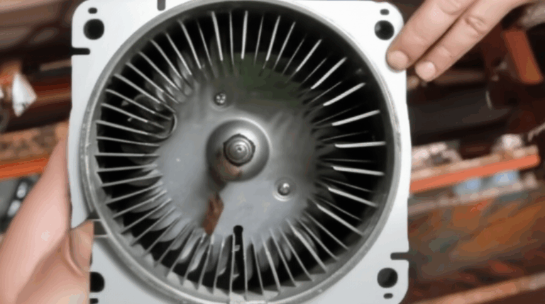
Part 3: Inside the Stator — Windings, Laminations, and Three-Phase AC
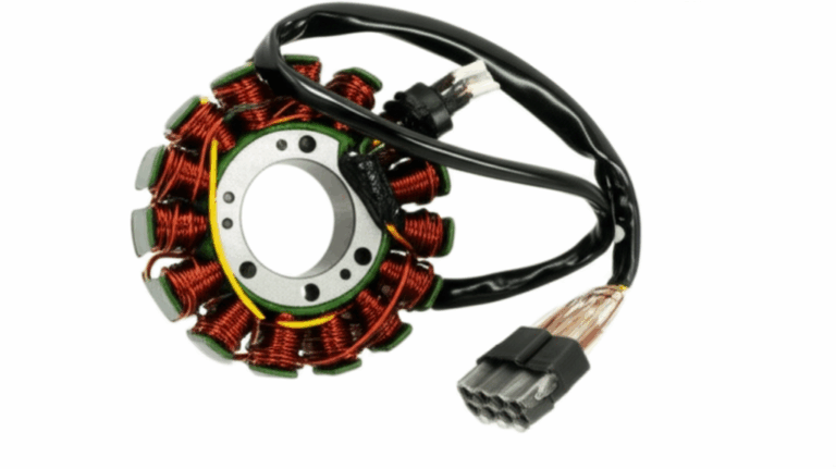
What is the stator? It’s the stationary core of the alternator. It houses copper windings, sits close to the rotor, and carries the three-phase output. It’s built from stacked laminations of electrical steel. Those laminations are stamped or cut to shape, then stacked to the specified height.
- Laminated iron core: A stack of thin steel sheets with insulation between layers. Typical thickness ranges from 0.2 to 0.65 mm depending on frequency and cost targets.
- Multiple windings: Usually three sets of coils displaced 120 electrical degrees apart for three-phase AC power.
- Slot geometry: Tooth width, slot depth, and tooth-tip design shift flux distribution and copper fill. Designers tweak these to balance efficiency, noise, and manufacturability.
The stator’s core material and geometry set your magnetic permeability (how easily magnetic flux flows), saturation margin, and core loss. You’ll see the effect in thermal maps and IR camera shots. You’ll feel it in the rectifier’s heat sink temperature.
If you’re gut-checking a design or a supplier’s stack quality, look at the lamination edges and the interlaminar insulation. Burrs increase local losses and hot spots. Poor insulation raises eddy current paths. Either one can tilt a borderline rectifier over the edge during a summer idle event.
For a deeper dive on stator construction and impact on performance, see the overview of stator core lamination.
Wye vs Delta: Which Winding Scheme?
- Wye (Star): Higher line-to-line voltage at a given number of turns which can improve low-speed charging. Better for reduced ripple current into the rectifier.
- Delta: Lower phase voltage and higher current capability which can boost output at higher speeds. It can increase circulating currents if not managed.
Pick the scheme that fits your duty cycle. City driving with lots of idling favors wye. Highway or high-RPM applications may prefer delta. Some designs switch between them electronically for the best of both worlds.
Permanent Magnet vs Wound Field Alternators
- Wound field alternator: The rotor carries a field coil powered through slip rings and brushes. The voltage regulator adjusts field current which controls output.
- Permanent magnet alternator (PMG): The rotor uses permanent magnets so it doesn’t need slip rings or brushes. You regulate voltage by phase chopping, shunt regulation, or field weakening if the design supports it.
PMG designs show up in motorcycles and small engines a lot. They run simple, produce strong output at low speed, and reduce wear points. The trade-off is control. Wound field alternators give you fine-grained regulation across a wide RPM band.
Part 4: Inside the Rectifier — Diode Bridge and Ripple Control
The rectifier converts three-phase AC into DC. Most automotive alternators use a six-diode, full-wave bridge. Some add extra diodes for improved current sharing or use MOSFET-based rectifiers for lower drop and better thermal behavior.
- Diode basics: A diode conducts in one direction with a forward voltage drop. Silicon diodes drop about 0.7 to 1.0 V at nominal current. Schottky diodes drop less but come with lower reverse voltage ratings.
- Full-wave rectification: Each diode pair routes both halves of the AC waveform to the positive output. That doubles the effective frequency and cuts ripple amplitude.
- Three-phase advantage: Because three phases overlap, the pulsating DC looks pretty smooth. The battery and wiring harness shunt remaining ripple. That’s why alternators deliver low ripple voltage without big smoothing capacitors.
Rectifiers ride a tough thermal cycle. Diodes dissipate heat due to forward drop times current. Heat sinks and solid thermal paths matter. Mounting quality matters too. A void in thermal compound can shorten life fast.
Acceptable ripple voltage on the DC bus usually sits below about 0.5 V AC RMS with the engine running. If you see higher ripple on an oscilloscope or a multimeter with AC mode, suspect a failed diode or poor connection.
Part 5: From Engine to Battery — The Charging System as a Whole
Let’s connect the dots and walk the power journey.
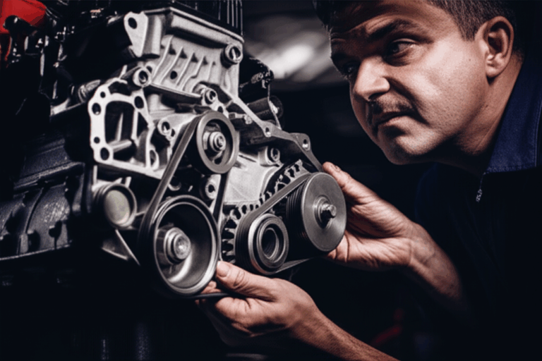
1) The engine rotates the alternator through a drive belt and pulley on the crankshaft.
2) The rotor spins and creates a rotating magnetic field. A wound field uses slip rings and brushes to energize the rotor’s electromagnet. A PMG uses permanent magnets.
3) The changing flux crosses the stator teeth and slots. That movement induces three-phase AC in the windings by Faraday’s Law.
4) The stator feeds the rectifier assembly. Diodes inside the heat-sinked bridge rectify AC to DC.
5) The voltage regulator monitors battery voltage and electrical demand then adjusts rotor field current in a wound-field alternator to keep output around 13.5–14.8 V.
6) The battery draws charging current while the DC bus powers lights, ignition, ECU, infotainment, and accessories in the vehicle electrical system.
Why generate AC then convert to DC? Rotating machines generate AC naturally with high efficiency. Rectification with diodes is simple, compact, and robust. Vehicles need DC for batteries and electronics so the conversion step earns its keep.
Part 6: Material Considerations for Stator and Rotor Laminations
Here’s where the lamination choices you make translate directly into how well the rectifier survives.
Core losses rise with frequency and flux density. They split into hysteresis and eddy current loss. Material composition and lamination thickness control both.
- Nonoriented silicon steels (NOES): The workhorse for alternators and general-purpose rotating machines. Silicon raises resistivity and reduces core loss. Grades often labeled M15 to M47 in legacy designations.
- Grain-oriented silicon steels (GOES): Optimized for transformers with flux in one direction. They shine in EI or UI transformer cores. Alternators need isotropic behavior so NOES fits better.
- Cobalt alloys: High saturation flux density and low loss at high frequency. You’ll see them in aerospace and high-power-density machines. Cost bites hard.
- Amorphous metals: Very low core loss at high frequency thanks to lack of crystalline grain boundaries. Manufacturing complexity and cost limit use in most alternators.
Thickness matters. Thinner laminations cut eddy current loops which drop eddy current loss. The trade-off is cost and manufacturing complexity. Insulation coating type matters as well. It controls interlaminar resistivity and stack bonding behavior.
If you want a broad overview of options and trade-offs, this guide to electrical steel laminations is a useful starting point. For mainstream motor and alternator designs, the family of silicon steel laminations typically provides the best performance-to-cost ratio.
Standards to anchor your choices:
- ASTM A677 and ASTM A976: Specifications and classification for electrical steels.
- IEC 60034 series: Rotating electrical machines. Definitions, test methods, and ratings.
- UL 1446: Systems of insulating materials. Relevant for long-term thermal life and stack insulation.
Rotor Laminations Also Matter
Don’t overlook the rotor. In wound-field alternators, the rotor core and pole pieces carry the field and set the flux path. In PMGs, the rotor supports magnets and defines the air-gap flux. Rotor material and geometry influence field strength, saturation behavior, and mechanical integrity at speed. Poor rotor design raises iron loss and heat which stress the rectifier from the other side.
If you’re evaluating a full stack-up, a quick primer on rotor core lamination will help you align material grades and manufacturing tolerances for both sides of the air gap.
Magnetic Property Trade-offs To Watch
- Permeability vs saturation: High permeability allows flux to move easily. High saturation holds performance at peak load. Balance both for your duty cycle.
- Loss vs cost: Lower loss grades cost more. Map the avoided diode temperature rise and longer life to dollars. The business case often works in high-heat duty cycles.
- Coating class: Classifies interlaminar insulation. Impacts bonding, welding, and interlock performance. Pick a coating that fits your assembly process.
Part 7: Manufacturing and Assembly Processes That Move the Needle
The best material in the world can’t save a sloppy stack. Manufacturing choices shape both electromagnetic performance and durability.
- Stamping: High-volume, consistent, low per-part cost once the tool pays off. Watch burr height and edge quality. Excess burrs raise local loss and hot spots.
- Laser cutting: Great for prototypes and complex or low-volume geometries. Heat-affected zones can raise loss if you don’t control parameters.
- Wire EDM: Clean edges and tight tolerances at higher cost. Useful for precision applications and material trials.
- Bonding vs mechanical interlocks: Bonding with adhesive coatings delivers rigid stacks and low vibration without welding heat. Interlocks work like a press-fit LEGO connection. They are fast and robust when designed well.
- Welding and cleating: Common for mechanical integrity. Manage heat input to avoid loss increases and residual stress.
- Stack height and skew: Skewing the stack can reduce cogging and noise. Skew slightly complicates assembly and may lower effective torque ripple.
You’ll get the best results when you align lamination grade, coating, and assembly process. If you must laser cut a NOES grade for prototypes, ask for cutting parameters that minimize HAZ and consider a post-process anneal if the grade allows it. If you plan high-volume stamping, limit burr height and control blank holding to prevent draw-induced edge variation.
When you need a refresher on the broad solution space, this overview of motor core laminations summarizes common stack types and where each shines.
Part 8: Troubleshooting, Testing, and Reliability Data
A quick reality check. Alternators are wear items. Heat and vibration set their life. Here’s what industry experience and field data typically show.
- Alternator lifespan: About 80,000 to 150,000 miles or 5–8 years in light vehicles with normal duty.
- Heat as the top culprit: Heat drives over half of failures in many fleets. Under-hood temperature plus high current draw plus long idle equals stress.
- Rectifier failure share: Diodes account for roughly one-third of alternator failures. Thermal cycling and voltage spikes do the damage.
- Stator failure share: Around 15–25% due to shorted or open windings. Causes include insulation breakdown, overheating, and vibration.
- Output voltage target: 13.5–14.8 V at the battery with the engine running and the system stable.
- Ripple voltage threshold: Less than 0.5 V AC RMS measured across the battery under normal load. Higher ripple flags a bad diode or poor connection.
You don’t need a lab to catch most issues. A multimeter and common sense get you far.
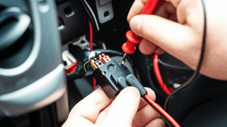
How to Test a Stator
- Resistance test: With the engine off and alternator isolated, measure phase-to-phase resistance between each pair of stator windings. Readings should match within a small tolerance. An open circuit points to a broken winding. A very low reading hints at a short.
- Ground fault test: Measure resistance between each winding and ground. You want a very high reading. Any low resistance indicates a short to ground.
- Output voltage test: With the engine running, measure AC voltage at each pair of stator leads before the rectifier if accessible. Expect similar voltages across phases proportional to speed.
How to Test a Rectifier
- Diode check mode: Many multimeters include a diode test. Isolate the rectifier. Check each diode in both directions. You should read a forward drop in one direction and open in the other.
- Ripple voltage: With the alternator running and a moderate load on, measure AC across the battery. Readings above 0.5 V AC RMS suggest a failed diode or poor wiring.
- Voltage drop tests: Under load, measure voltage drop across the main alternator output cable and ground path. Excessive drop costs you charging headroom.
Symptoms you’ll see on the road:
- Battery warning light on.
- Dim or flickering headlights.
- Electronics that reset at idle or under sudden load.
- Burning smell near the alternator which hints at overheated windings or diodes.
- Dead battery after an overnight sit due to a shorted rectifier diode that back-drains the battery.
Why Lamination Choices Shape Reliability
High core loss runs the stator hotter. Hot windings raise copper resistance which cuts output and drives the regulator to increase rotor field current. The rectifier then carries higher current which increases diode heating. The cycle feeds on itself during long idle periods when airflow is low. Thinner laminations and better grades pay for themselves in lower diode temperatures and longer insulation life.
Voltage Regulation and System Components
- Voltage regulator function: It senses battery voltage and temperature then adjusts rotor field current to hold the setpoint. Modern ECUs can command different charge profiles for fuel economy or battery life.
- Smoothing capacitors: Alternators usually rely on the battery as the smoothing element. You might see additional capacitors for EMC.
- Fuses and circuit breakers: Protect the alternator output and wiring harness. They also complicate voltage drop measurements so note their positions.
- Warning light circuit: Often provides excitation current at startup in some designs. A blown bulb can delay charging in older systems.
Part 9: Which Application Is This For?
Different markets push different constraints. Let’s match the right stator and rectifier approach to your use case.
Automotive Alternators
- Duty cycle: Wide RPM range. Frequent heat soak. Idling with loads like HVAC and lights.
- Best bets: Wound-field alternators with robust heat-sinked rectifiers. High-quality NOES laminations in the stator with controlled burrs and a consistent interlaminar coating.
- Notes: Target ripple below 0.5 V AC. Keep charging at 13.5–14.8 V. Work with the vehicle’s ECU-controlled regulator strategy to protect battery life.
Motorcycles and Small Engines
- Duty cycle: High RPM, less airflow when stationary, space constrained.
- Best bets: Permanent magnet alternators with a shunt or series-type regulator-rectifier. Use high-temperature insulation on stator windings and carefully select lamination thickness to manage loss at RPM.
- Symptoms of failure: Battery not charging, flickering lights, melted regulator connectors, or overcharging that cooks a small battery.
- Testing: Stator AC output across phases should scale cleanly with RPM. Any phase mismatch suggests a winding fault.
Marine Alternators
- Duty cycle: High load at lower RPM with long run times. Corrosive environment.
- Best bets: Wound-field alternators with heavy-duty rectifiers and heat sinks. Conformal coating and sealed connections. Focus on thermal design around the rectifier.
- Key watch-outs: Extended idling near docks increases heat. Ventilation and rectifier thermal margin matter.
Industrial Generators
- Duty cycle: Steady RPM for long periods. Predictable loads.
- Best bets: Materials and lamination thickness tuned to the running frequency. Consider tighter manufacturing tolerances and skewed stacks to reduce noise and torque ripple.
- Testing: Oscilloscope checks on ripple and harmonics help predict rectifier stress and battery life in DC-coupled systems.
Part 10: Your Options Explained (The Guide You Can Use Today)
Let’s pull choices into two buckets: materials and manufacturing. Then we’ll layer in winding and topology.
Material Considerations
- NOES silicon steel for rotors and stators in most alternators: Balanced cost, low loss, and good availability.
- Higher-alloy NOES or cobalt alloys for high RPM or high ambient temperature duty where rectifier life has been a pain point.
- Thinner lamination gauges when you must cut eddy current loss at elevated frequency content. Balance with cost and stack integrity needs.
- Coating class that supports your bonding or interlock approach and your operating temperature target.
If you want a refresher on the building blocks, these primers on silicon steel laminations and electrical steel laminations outline common grades and trade-offs.
Manufacturing and Assembly
- Prototype phase: Laser cut or EDM a small batch. Measure loss with and without a post-cut anneal if the material allows it. Validate edge quality.
- Production phase: Stamp with a robust die set. Control burr height. Verify interlaminar resistance. Use bonding or interlocks to stabilize the stack.
- Quality controls: Map loss vs frequency on test laminations. Check stack height and skew consistency. Inspect coating integrity after forming and assembly.
Winding Scheme and Topology
- Wye for better low-speed charging and lower ripple into the rectifier.
- Delta for high-speed output and higher current which heats the rectifier more.
- Wound-field for precise regulation across RPM. PMG for simplicity and high specific output at lower speeds.
- Three-phase bridge rectifier with generous heat sinking. Consider MOSFET rectifiers for lower loss in tight thermal envelopes.
System Integration
- Regulator strategy that adapts to load and ambient conditions.
- Cabling sized to hold voltage drop within tight limits under peak load.
- Placement that ensures airflow across the rectifier and stator housing.
- EMC filters where needed to control conducted and radiated emissions from the diode switching and wiring.
Part 11: Practical Testing and Design Validation
You don’t need to guess. Validate your design early.
- Spin bench test: Map output current vs RPM and temperature. Watch rectifier case temperature.
- Thermal camera: Identify hot spots at the stator teeth and rectifier heat sink. Hot spots often trace back to lamination edge quality or poor thermal paths.
- Oscilloscope: Check DC bus ripple and phase waveforms under load. Look for phase imbalance and diode switching anomalies.
- Environmental runs: Idle soak at high ambient. High-load low-RPM operation. Cold starts. Cycle the worst cases.
For documentation and compliance, reference applicable standards:
- IEC 60034 for performance and testing methods.
- ASTM A677 and A976 for material verification.
- UL 1446 for insulation systems if you need third-party recognition on stacked cores.
Part 12: Common Problems and Symptoms (Plus Why They Happen)
Stator issues:
- Low or no charge.
- Battery light on.
- Burning smell from overheated windings.
- Root causes: Open or shorted windings, insulation breakdown from heat, or ground faults amplified by vibration and moisture.
Rectifier issues:
- Undercharging or intermittent charging.
- Overcharging due to regulator reference errors or diode leakage.
- Flickering lights and electrical noise.
- Root causes: Failed or leaky diodes, poor thermal coupling to the heat sink, voltage spikes from load dumps.
System-level causes:
- Battery near end of life that pulls high charging current and overheats the alternator.
- Loose grounds or corroded connectors that drive up voltage drop.
- Drive belt slip that reduces alternator speed under load.
Cost reality check:
- Rectifier replacement parts are inexpensive compared with the cost of downtime.
- Poor lamination and thermal design drive repeated failures which cost more in labor and brand equity than the original savings.
Part 13: Frequently Asked Engineering Questions
Why is AC generated first in alternators?
Rotating magnetic fields naturally induce AC in stationary windings. AC generation is efficient and mechanically simple. Rectification to DC with diodes or MOSFETs is compact and reliable.
How does the alternator charge the battery?
The voltage regulator holds the DC output above the battery’s open-circuit voltage. The difference drives current into the battery. As the battery charges, current tapers off.
Do we need a smoothing capacitor after the rectifier?
The battery serves as a huge capacitor. Three-phase rectification produces low ripple so additional smoothing capacitors are minimal unless EMC requires them.
Wye or delta for three-phase stator windings?
Pick based on duty cycle. Wye helps at low speed. Delta can favor high-speed output. Some systems switch between the two.
How do lamination stacks affect rectifier life?
Lower core loss drops stator temperature which lowers winding resistance and current demand which reduces diode dissipation. Cooler diodes live longer.
What about transformer laminations like EI or UI?
EI and UI cores suit transformers where flux flows along grain-oriented steel. Alternators need nonoriented laminations shaped for stator teeth and slots. Different game, different geometry, different steel selection.
Part 14: “Best Fit” Guidance by Scenario
- You run a fleet with extended idling. Heat kills rectifiers. Move to thinner laminations in the stator, upgrade to a lower-loss NOES grade, and spec a rectifier with higher current diodes and a better heat sink.
- You build motorcycles with PMGs. Use high-temperature insulation and pay for edge quality on laminations. Pick a series regulator-rectifier to cut waste heat at cruise.
- You design a compact alternator for a hybrid accessory drive. Consider higher grade NOES or cobalt alloy in a tight stack, skew the stator, and evaluate a MOSFET rectifier for lower loss.
- You’re cost constrained for mass-market vehicles. Stamp NOES laminations with tight burr controls, wye wind for low-speed performance, and use a proven six-diode bridge with robust heat sinking.
Part 15: Your Engineering Takeaway (Empowerment and Next Steps)
If you remember nothing else, remember this:
- The stator generates three-phase AC through electromagnetic induction.
- The rectifier converts that AC to DC so the vehicle can use it.
- Lamination material, thickness, and edge quality drive core loss and heat which directly impact rectifier temperature and life.
- Winding scheme, rotor topology, and regulator strategy tune performance across RPM and load.
- Testing early with a spin bench, oscilloscope, and thermal camera pays for itself by catching hotspots and ripple issues before production.
Actionable next steps:
- Ask suppliers for core loss data at your operating flux density and frequency. Don’t accept single-point numbers at 60 Hz if you run far higher electrical frequency.
- Specify maximum burr height and interlaminar resistance. Inspect edges and coating after sample builds.
- Define ripple voltage acceptance at the battery and test it with a loaded system.
- Map rectifier case temperature vs load and RPM during an idle heat soak test.
- Align lamination grade and thickness with your rectifier thermal budget. Spend on steel if it saves your diodes.
Still deciding on stack configuration or material grade for a new platform? Review rotor and stator options together so the air-gap flux, saturation margin, and thermal path line up. A quick technical consultation can shorten that loop and reduce your risk.
For a concise overview of rotor considerations alongside stator design, see rotor core lamination. For stator geometry and stack strategies, start with stator core lamination. If you want to brush up on the broader material landscape, these primers on electrical steel laminations and silicon steel laminations offer practical context for design and procurement decisions.
Final thought: Clarity beats complexity. When you cut core loss and manage heat, the rectifier breathes easier, the battery lives longer, and your system runs better. That’s good engineering and good business.