The Fundamental Energy Transformation in an Electric Motor: Electrical to Mechanical Motion
Table of Contents
Introduction: Why Motors Matter and What They Transform
I still remember the first time I tore down a small DC motor from an old printer. I wanted to know why a couple of wires and a cylindrical shell could spin a shaft with such eager force. It looked plain on the outside. Inside it felt like a magic trick. That curiosity turned into a career spent specifying, testing, and troubleshooting motors in factories, labs, and garages. Over the years I learned a simple truth. The heart of every electric motor is a very clean and very repeatable energy transformation.
What energy transformation occurs in a motor? That question might sound basic. It sits at the center of everything from robot joints to electric vehicle drivetrains to the fan over your kitchen stove. If you get the transformation right you get predictable motion with minimal waste. If you miss key details you heat the room, you drain your battery, and you wear out parts early.
Let me walk you through how this conversion works, why efficiency matters, and what really happens to each watt you feed into a motor.
The Short Answer: Electrical Energy to Mechanical Energy
An electric motor’s primary energy transformation is simple. It converts electrical energy into mechanical energy in the form of rotational motion and torque. Input energy arrives as current and voltage. Output energy leaves as kinetic energy at the shaft that does mechanical work. That’s the core. Along the way some of the input turns into heat and a little turns into sound or vibration.
Two lines sum it up:
- Electrical Energy → Magnetic Field → Force → Mechanical Energy
- Electrical Input = Mechanical Output + Losses (mostly heat)
How an Electric Motor Actually Turns Electricity into Motion
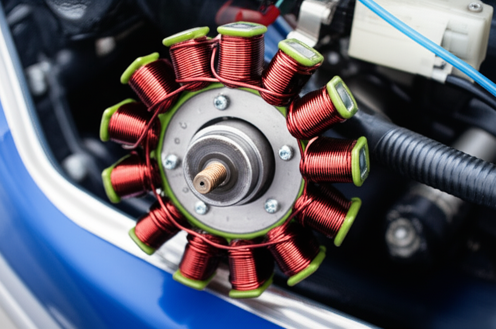
The Basic Ingredients: Stator, Rotor, Coils, Magnets, and Current
When I explain motors to friends I start with the parts you can see.
- Stator: The stationary part. It holds coils or permanent magnets. It sets up a magnetic field that the rotor reacts to.
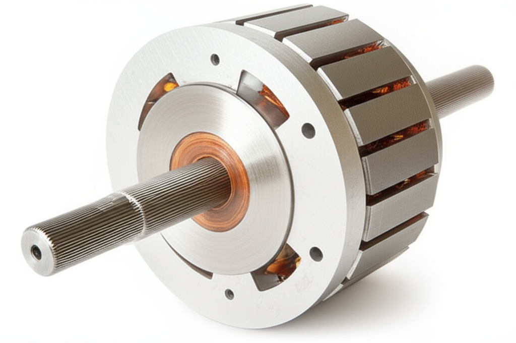
- Rotor: The rotating part. It carries windings or conductive bars. It sits inside the stator field and turns when forces act on it.
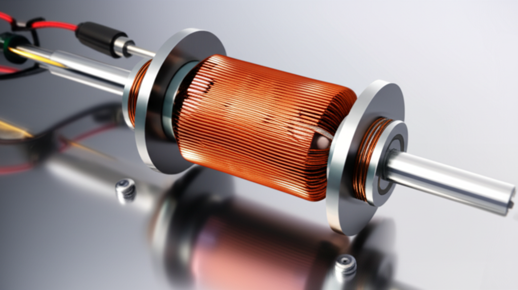
- Coils and Windings: Copper wire arranged in slots. When current flows through them they create magnetic fields.
- Magnets: Either permanent magnets or electromagnets. They provide the magnetic field that interacts with current-carrying conductors.
- Current and Voltage: The electrical energy you feed into the coils. Current through a conductor in a magnetic field creates force.
When you pass current through coils you energize them. The field they create wants to align or misalign with another field. That dance produces continuous torque if you manage the timing right.
For a deeper look at why the steel core matters in this dance I often point friends to resources on stator core lamination and rotor core lamination. Laminations reduce eddy currents and hysteresis losses which means less heat and more useful motion.
The Physics Bridge: Electromagnetism, Lorentz Force, and Faraday’s Law
I keep two simple laws in mind.
- Lorentz Force: A current-carrying conductor in a magnetic field feels a force that is perpendicular to both the current and the field. This is the push that creates torque. It is the “muscle” of the motor.
- Faraday’s Law of Induction: Changing magnetic flux induces a voltage in a conductor. In motors this shows up as back EMF which grows with speed and influences current draw and torque.
In other words current creates magnetic fields. Magnetic fields interact and produce force. The force produces motion. Motion changes flux which induces voltages that push back. The system finds balance based on load, speed, and applied voltage.
Keeping It Spinning: DC Motors vs AC Motors
Different motor types sustain rotation in different ways. That detail is where I see most confusion vanish.
- DC Motors: A brushed DC motor uses a commutator and brushes to mechanically switch current direction in the rotor windings. That keeps torque in the same direction as the rotor turns. You get solid low-speed torque and simple speed control with voltage.
- AC Motors: An AC motor uses alternating current to create a rotating magnetic field in the stator. The rotor “chases” this field. In an induction motor the rotor sees induced currents which create a secondary magnetic field that interacts with the stator field to produce torque. In synchronous motors with permanent magnets the rotor locks to the rotating stator field.
Modern control electronics take this further. A variable frequency drive (VFD) changes the frequency of the AC feeding the stator which sets the synchronous speed. Field-oriented control in permanent magnet synchronous motors (PMSM) and brushless DC (BLDC) motors adjusts currents in multiple phases to create optimal torque with minimal losses. That’s where power electronics and motor control systems show their worth.
Energy Flow Inside a Motor: From Input to Useful Work
The Energy Balance: Where the Watts Go
I like a simple energy diagram you can sketch on a napkin.
Input Electrical Power (Watts) →
- Magnetic Field Energy →
- Torque Generation (Lorentz force) →
- Mechanical Output (shaft power in Watts) →
- Useful Work on the Load (kinetic energy) +
- Unavoidable Losses (heat and sound)
Or in equation form:
Pin = Pout + Ploss
Where Ploss includes:
- Copper losses (I²R in windings)
- Core losses (hysteresis and eddy currents in the iron)
- Mechanical losses (bearing friction and windage)
- Stray load losses and a touch of acoustic/vibration energy
The Usual Suspects: Ohmic, Core, Friction, Windage, Sound, and Vibration
Here is how each loss source eats energy and turns it into heat or noise.
- Electrical Losses (Copper/I²R): Current flows through windings with resistance. The formula is I²R and it turns straight into heat in the copper. High current means more heat. Heavier copper and lower resistance help but you pay with cost and size.
- Core Losses (Magnetic): The motor’s magnetic core gets magnetized then demagnetized with each cycle. That costs energy due to hysteresis. Time-varying fields also induce eddy currents in the core which create more heat. Thin laminations of electrical steel block large eddy loops which reduces loss.
- Mechanical Losses: Bearings rub. Seals drag. Gears mesh. Air swirls around the rotor and housing which is called windage. All of it shows up as heat.
- Sound and Vibration: Minor but real. Slotting forces, magnet forces, bearing roughness, and unbalance all contribute to audible or ultrasonic energy.
In a typical industrial motor the breakdown of total losses often looks like this:
- 30–40% copper losses
- 20–30% core losses
- 10–20% mechanical losses
- 10–15% stray load losses
Sound is small yet it hints at friction and imbalance which can signal bigger issues.
I have seen core loss spikes when cheap material or poor stacking lets eddy currents run wild. Better motor core laminations and clean stack assembly turn that around fast.
Heat Happens: Thermal Management in Real Life
Heat is both symptom and cause. High copper loss raises winding temperature. Higher temperature raises resistance which increases copper loss at the same current. That positive feedback loop can cook a motor if cooling falls short. I pay close attention to:
- Cooling paths and airflow
- Thermal interface between windings and stator slots
- Insulation class and temperature rise
- Bearing lubrication and preload
- Ambient conditions and altitude
I once reduced a persistent overheating problem on a 30 kW pump motor by switching to a premium efficiency model with better core steel and improved fan design. Same duty cycle. Lower current and lower skin temperature. The energy meter told the story.
If you want to dig deeper into the iron itself you will bump into electrical steel laminations. The choice of grade and thickness sets the tone for eddy current and hysteresis behavior.
What Efficiency Really Looks Like in the Wild
Efficiency Ranges and IE Classes
Motor efficiency varies with size, design, and load. I use the IEC 60034-30-1 framework as a mental map.
- IE1 Standard efficiency: roughly 75–85%
- IE2 High efficiency: roughly 82–89%
- IE3 Premium efficiency: roughly 87–94%
- IE4/IE5 Super premium: roughly 90–97%+
Bigger motors usually do better. They have proportionally less surface area for heat loss and more room for copper and iron. Peak efficiency often shows up near 75–100% of rated load. Run too light and fixed losses dominate. Run above rated load and copper loss explodes.
In high-performance EV motors like BLDC and PMSM I often see system efficiencies of 90–97% under sweet-spot conditions. That is a big reason EVs feel so crisp. Most of the battery’s electrical energy becomes mechanical energy at the wheels.
Why Motors Dominate Electricity Use
Electric motors consume on the order of 45–50% of global electricity. In industry that share can hit 65–70%. I saw this firsthand during plant energy audits. Air compressors, pumps, conveyors, and fans never rest. Their motors run long hours which means every percentage point of efficiency turns into serious money and lower emissions.
Here is the kicker. More than 95% of a motor’s lifecycle cost comes from the electricity it consumes. Purchase price is often below 5%. Spend a little more up front and you can save a lot over the next decade.
Oversizing, Load, Power Factor, and Control
I have lost count of oversized motors I have seen. Someone picks the next size up “to be safe” then the motor spends its life at 35–50% load. That hurts efficiency by 5–15 percentage points in many cases. It also worsens power factor which drags on the electrical supply. Right-sizing and trimming load through proper process control often pays back fast.
Power factor matters because reactive power swells current without adding useful work. Induction motors at light loads can have poor power factor which raises I²R losses upstream. Variable frequency drives can help. They match speed to demand which slashes energy in fan and pump applications due to the affinity laws.
I like to say: control speed and torque smartly and you control energy. A variable frequency drive on a centrifugal pump can cut power use dramatically because power scales with the cube of speed. Slow the impeller a little and you save a lot.
Popular Motor Types and Their Energy Behavior
DC Motors: Brushes, Commutators, and Simple Control
The brushed DC motor is the friendliest to learn on. Apply voltage and it spins. Torque roughly follows current. Speed roughly follows voltage minus back EMF. Brushes and commutators bring wear and friction which show up as mechanical and electrical loss. Heat at the commutator is wasted energy. I used them when I wanted low-speed torque without complex electronics. In high-duty applications the brush maintenance drove me to step up to brushless solutions.
Induction Motors: Workhorses of Industry
The squirrel-cage induction motor powers much of the world. Three-phase AC creates a rotating magnetic field in the stator. The rotor sees induced currents which generate torque. No brushes and a rugged rotor make it reliable. The price you pay is slip. The rotor must lag the stator field slightly to keep inducing current which becomes heat in the rotor bars and end rings. These motors respond well to VFD control that trims speed to load.
Good rotor and stator steel reduce core losses. Low-resistance copper in the rotor improves efficiency but costs more. Bearings and fans deserve care because friction and windage eat energy around the clock.
Brushless DC and PMSM: EV-Grade Efficiency
Brushless DC motors and permanent magnet synchronous motors replace brushes with electronic commutation. Sensors or sensorless algorithms time the currents so the stator field pulls the rotor magnets around smoothly. Field-oriented control keeps torque high and losses low. That is why EV motors stay efficient across a broad speed range.
Torque production in PMSM and BLDC is clean which shows up as quiet operation with low vibrational energy. You still have core losses at high electrical frequency. You still have copper losses with heavy current. Good cooling and smart drive mapping keep temperatures in check.
Stepper and Servo Motors: Precision vs Energy Dynamics
Steppers move in discrete steps which makes positioning simple. They can hold a load at standstill which is useful yet it burns energy because coils often stay energized to hold torque. That heat is not “free”. I learned to reduce holding current where possible and to use mechanical brakes when it made sense.
Servo motors add feedback and adjust current in real time to deliver the torque the load demands. That closed loop reduces wasted energy and improves dynamics. In modern robotics servos let you minimize overshoot and vibration which saves time and energy across cycles.
Practical Ways to Improve Efficiency and Reduce Losses
Design Details That Matter
I have chased losses inside motors down to the nuts and bolts. A few design decisions pay off big.
- Laminations and Core Steel: Thin laminations with tight stacking and low-loss electric steel reduce eddy current and hysteresis losses. Choosing the right grade and thickness matters. This is where motor core laminations and the specifics of stator and rotor stacks earn their keep.
- Slot Fill and Copper Quality: More copper in the slot lowers resistance which cuts I²R loss. That means careful winding design and sometimes better conductor shape.
- Airgap Consistency: A small and uniform airgap boosts magnetic coupling which raises torque per amp. Tight tolerances help.
- Cooling Path: Longer life and steadier efficiency come from predictable thermal paths. Good fans, shrouds, or liquid jackets make heat flow out not back into the windings.
- Bearings and Seals: Quality bearings with correct preload and lubrication reduce friction loss. Misalignment kills efficiency and bearings fast.
When evaluating laminations I like to examine options such as stator core lamination and rotor core lamination choices. Material loss curves and thickness drive the eddy current story. If I need a primer for a colleague I share a broad overview of motor core laminations. If we are sourcing materials we also discuss the grade and properties of electrical steel laminations.
Smarter Controls and Power Electronics
Power electronics changed the game. With VFDs and advanced inverters you can:
- Match motor speed to load instead of throttling with valves or dampers
- Improve power factor at the input side
- Reduce inrush current and mechanical stress
- Optimize current vectoring in PMSM/BLDC for higher torque per amp
In pump and fan systems I often see 20–50% energy savings after adding VFDs with proper control logic. You burn less electricity and you reduce wear because the machine stops fighting itself.
Maintenance, Alignment, and System-Level Fixes
You can spec the best motor on paper then lose the battle in the field. Real-world fixes that always help:
- Keep the drive aligned with the load. Misalignment adds friction and vibration
- Use proper motor sizing. Don’t pick a 30 kW motor for a 10 kW job
- Maintain bearings and seals. Replace before they grind up heat
- Balance the rotor and couplings to cut windage and vibration
- Audit the system not just the motor. Restrictive piping or clogged filters force unnecessary load
Energy auditing motor systems pays back. I have watched a simple fix like a cleaned filter or a trimmed impeller reduce power draw in minutes without touching the motor.
A Quick Comparison: Motors vs Generators and Regeneration
A motor converts electrical energy to mechanical energy. A generator does the reverse. Mechanical energy spins the rotor and electrical energy flows out. This comparison helps when you meet regenerative braking in EVs. During braking the traction motor behaves like a generator. Mechanical energy from the wheels turns the rotor. Electrical energy flows back into the battery. You do not get energy from nothing. You simply recover some kinetic energy that would have become heat in friction brakes.
In that sense a motor is an energy conversion device that can work both ways. It depends on the direction of power flow and the control strategy.
My Simple Energy Diagram and Cheat Sheet
When I teach this I use a simple flow with words that tie back to the physics. It is not pretty yet it sticks.
- Electrical Input: Voltage and current enter the windings
- Magnetic Field: Current in coils creates magnetic fields
- Interaction: Stator field and rotor field interact
- Force: Lorentz force creates torque on the rotor
- Motion: Rotor spins and delivers mechanical power at the shaft
- Useful Work: The load absorbs power as kinetic energy and work done
- Losses: Heat in copper and iron, friction and windage, a bit of sound and vibration
If you like equations:
- Mechanical Power at the shaft (Watts) = Torque (N·m) × Angular Speed (rad/s)
- Efficiency η = Pout / Pin
- Pin = Pout + Pcu + Pcore + Pmech + Pstray
Watch speed and torque because they dictate the mechanical energy output. Speed and torque drive motor sizing and efficiency as they control where you run on the motor’s performance map.
Common Questions I Hear and How I Answer Them
- What kind of energy does a motor produce? Mechanical energy in the form of rotational motion and torque. That turns into kinetic energy of loads such as pumps, fans, compressors, or wheels.
- Where does the “wasted” energy go? Mostly into heat in copper windings and the magnetic core. Some goes into friction and windage. A small amount becomes sound energy from vibration.
- Why does a motor get hot when it runs with no load? Fixed losses like core loss and friction still exist even at light load. At very low load they can be a large share of input power which makes heat.
- What causes motor rotation? A magnetic field acting on a current-carrying conductor produces force. Proper timing of fields creates continuous torque. In DC motors a commutator does this. In AC motors the stator’s rotating field does it. In BLDC and PMSM the drive electronics do it.
- How do I maximize motor efficiency? Right-size the motor. Use premium efficiency designs. Improve cooling. Add VFDs where speed control helps. Maintain alignment and bearings. Audit the system to remove useless pressure drops or restrictions.
- Do premium efficiency motors always save money? Over a motor’s life energy dominates cost. If the motor runs many hours at decent load a premium or super premium motor usually pays for itself. If duty is short or intermittent do the math first.
- Does power factor affect energy use? Low power factor raises current which increases I²R losses upstream. Correcting power factor reduces wasted heat in cables and transformers. It also frees capacity.
Conclusion: The Power of a Clean Energy Transformation
I started my motor journey by guessing that some hidden trick turned electricity into spin. The trick turned out to be clear physics and careful engineering. An electric motor converts electrical energy into mechanical energy using electromagnetism as the bridge. Current creates magnetic fields. Fields interact and produce Lorentz force. Force creates torque and motion. The output does useful work while losses become heat and a little sound.
We cannot escape losses yet we can squeeze them. Better laminations and copper reduce electrical and core losses. Smarter drives cut wasted energy in variable loads. Right-sizing, clean alignment, and maintenance keep systems honest. In a world where motors drink nearly half of our electricity we cannot afford to ignore any watt.
If you remember one thing remember the transformation. Electrical energy in. Mechanical energy out. Everything else is about making that transformation cleaner, cooler, and more efficient at every speed and every load.