TCO of Self-Bonding vs. Welding for Motor Cores: Unpacking the True Costs and Benefits
Every engineering leader faces the same tough call at some point. How should we assemble our motor core laminations to hit performance targets without blowing up our total cost of ownership? If you’re weighing self-bonding adhesives against welding for stator and rotor stacks, you’re in the right place. This guide breaks down the physics, the process realities, and the dollars-and-cents impact so you can make a confident decision for EV traction motors, industrial drives, robotics, or generators.
You’ll see where adhesive bonding shines with magnetic performance and NVH. You’ll also see why welding still wins in certain high-stress or high-throughput lines. We’ll keep it practical. We’ll focus on TCO—total cost of ownership—since upfront price rarely tells the whole story in electric motor manufacturing.
Before we dive in, a quick reminder. Your choice affects more than assembly cost. It touches the magnetic flux path, core loss, NVH, dimensional stability, throughput, and even downstream warranty exposure.
In short, this is a cornerstone decision. Let’s make it with eyes wide open.
In This Article
- Why this choice matters for motor performance and cost
- The engineering fundamentals behind bonding and core losses
- Self-bonding vs. welding: processes, pros, cons, and trade-offs
- A TCO analysis framework: CapEx, OpEx, and lifecycle impacts
- Comparative performance: magnetic, mechanical, NVH, and quality control
- Application fit: EV traction, industrial, robotics, and generators
- Data-driven examples and an illustrative TCO model
- Decision checklist and next steps
Introduction: The Critical Choice in Motor Core Manufacturing
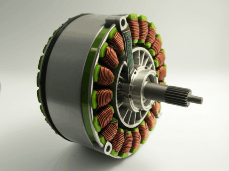
Your motor lives or dies by the quality of its motor core. The core’s lamination stack controls magnetic performance, core loss, NVH (noise, vibration, harshness), and durability. How you assemble that stack matters. Adhesive self-bonding and welding are the two most common methods for joining laminations in motor core laminations. Each method leaves a fingerprint on total cost of ownership (TCO).
- Self-bonding uses an adhesive coating on the electrical steel, then cures it with heat to join the stack.
- Welding joins laminations with localized fusion. Laser welding and resistance/spot welding are the usual suspects.
If you only look at equipment price and cycle time, you’ll miss the big picture. TCO accounts for CapEx, OpEx, and lifecycle performance like energy loss, rework, warranty risk, and customer satisfaction. That’s where today’s decision becomes tomorrow’s competitive edge.
What’s Really Going On? The Engineering Fundamentals
Let’s level-set the physics in plain terms. Laminations exist to fight eddy current losses. Think of eddy currents like little whirlpools that form when a changing magnetic field flows through solid steel. Those whirlpools waste energy as heat. Thin, insulated laminations break up the whirlpools, which slashes core loss and keeps efficiency high.
Two main loss mechanisms drive your energy math:
- Eddy current loss: Proportional to thickness squared and frequency squared. Good insulation between laminations lowers it.
- Hysteresis loss: A function of material properties like coercivity, which is a material’s resistance to demagnetization, and the B-H curve.
Bonding and welding change these losses in different ways.
- Adhesive bonding preserves the insulating layer between laminations. It maintains high surface insulation resistance which limits inter-lamination shorting. That usually means lower eddy current losses.
- Welding creates metallic bridges at weld points. Those bridges can short laminations locally and raise eddy current loss. You can mitigate the impact with optimized weld patterns and minimal heat input but some added loss is common.
You also face NVH considerations. Adhesive layers act like tiny vibration dampers that attenuate ringing and high-frequency noise. Welded stacks form a rigid structure that can transmit vibration more efficiently unless you tune the design and the process.
Thermally, welding introduces a heat-affected zone (HAZ). The HAZ can alter grain structure locally and add stress which sometimes needs stress relief or post-processing. Adhesive bonding requires heat as well since you cure the resin. Yet it avoids localized melting and the microstructural shifts that follow.
Finally, dimensional accuracy and distortion matter. Welding can introduce distortion or warp if clamping is weak or parameters drift. Adhesive bonding distributes loads and can protect stack geometry. Both approaches demand good fixturing, tight process parameters, and real quality control.
Understanding Self-Bonding Technology for Motor Cores
Self-bonding relies on an adhesive resin pre-applied to the electrical steel or applied during stacking. After stacking and clamping, you cure the resin. You can use batch curing ovens or continuous flow ovens. Induction heating sometimes helps if the design and resin allow it.
Process overview:
- Stamping or laser cutting of laminations
- Stacking with alignment and fixture control
- Adhesive application if not pre-coated
- Heat curing in an oven or via induction
- Cool down and quality checks
Key benefits:
- Magnetic performance: Adhesive layers preserve electrical isolation. That reduces eddy current losses and helps maintain magnetic permeability.
- NVH: The adhesive acts as a vibration damping layer. Many teams report improvements in noise and harshness when switching from rigid joints to bonded laminations.
- Design flexibility: Complex geometries and very thin laminations benefit from minimal localized heat input. You can push slot features and compact packaging.
- Scrap rate reduction: Minimal distortion risk lowers rework and scrap if process control is solid.
Key considerations:
- Adhesive cost: Proprietary self-bonding coatings add material cost per core.
- Curing time: Cure adds cycle time unless you run smart batch or continuous lines that hide that time on the critical path.
- Temperature sensitivity: High-temperature duty cycles need resin systems with proven high-temperature adhesive performance.
- Quality control: You must validate cure, check for voids, verify surface insulation resistance, and ensure dimensional accuracy.
Typical equipment:
- Adhesive dispenser technology and coating systems
- Curing oven technology
- Precision stacking fixtures and clamping
- Inline vision for alignment and surface coverage
- Material handling and automation for high-volume runs
Understanding Welding Technology for Motor Cores
Welding for motor cores includes laser welding and resistance/spot welding. You stack laminations in a fixture, clamp tightly, then apply targeted welds along the outer diameter, the yoke, or near the tooth roots depending on the design and the process window.
Process overview:
- Stamping or laser cutting of laminations
- Stacking and tight clamping
- Laser welding or resistance spot welding with tuned parameters
- Cool down and post-processing if needed
- Dimensional and magnetic checks
Key benefits:
- Mechanical strength: Welds create a robust fusion joint. Many high-speed rotors need this strength margin.
- Fast welding cycle: The welding operation itself is fast. Automated lines can achieve short cycle times per core.
- Established technology: Welding is well understood in mass production. Most plants know how to scale it.
Key considerations:
- Heat-affected zones: Localized heat can change microstructure and add stress.
- Distortion or warp: If clamping is not perfect or energy input runs high you can see distortion which drives rework costs.
- Magnetic performance: Welds create conductive bridges that can increase eddy currents. Optimized weld patterns and lower energy mitigate the impact but not always fully.
- Post-processing: You may grind weld beads or perform stress relief to meet tight dimensional accuracy.
Typical equipment:
- Laser welders with optics, power sources, and protective gases
- Resistance welding machines with electrodes and power control
- Clamping systems and fixtures built for repeatability
- Inline vision, leak checks for shorts, and post-weld straightness checks
Total Cost of Ownership (TCO) Analysis: Self-Bonding vs. Welding
You don’t pick a bonding method based on a single line item. TCO includes initial CapEx, operational costs, and lifecycle performance. You should also weigh risk, scrap, and supplier expertise.
Below we outline a practical model that you can adapt in your cost spreadsheet.
A. Initial Capital Investment (CapEx)
Equipment:
- Self-bonding: Curing ovens, adhesive applicators, precision stacking, conveyors, and automation. Typical equipment ranges run from roughly $200,000 to $700,000 depending on volume and oven configuration.
- Welding: Laser or resistance welders, optics, power, clamping, smoke/fume extraction, and automation. Typical ranges run from roughly $300,000 to over $1,000,000 for high-end laser systems.
Tooling and fixtures:
- Both methods need precise fixturing to maintain dimensional accuracy. Welding fixtures often run more robust and sometimes pricier due to clamp rigidity requirements. Budget on the order of tens of thousands of dollars per tool set.
Facility requirements:
- Self-bonding: Ovens add heat load and need airflow, safety inspections for resins, and well-designed material handling.
- Welding: You’ll need fume extraction and safety systems. Laser welding requires controlled environments to protect optics and operators.
Equipment depreciation:
- Model depreciation across the expected life. Welding gear sometimes carries higher annual maintenance and calibration costs which affects your depreciation strategy and your ROI (return on investment) calculations.
B. Operational Costs (OpEx)
Material costs:
- Self-bonding: The adhesive or pre-coating adds $0.50 to $2.50 per core in many lines. Validate with your supplier since chemistry and coverage vary.
- Welding: “Material” costs are low and energy dominates. Some resistance welding setups use consumable electrodes that you’ll replace on schedule.
Energy consumption:
- Self-bonding: Curing ovens consume roughly 0.5 to 1.5 kWh per core depending on oven efficiency and stack mass.
- Welding: Welding processes consume roughly 0.8 to 2.0 kWh per core with higher peak demand.
Labor:
- Both methods can run highly automated. Self-bonding often needs fewer setup interventions once dialed in. Welding may require specialized programming and more frequent parameter checks.
Maintenance:
- Self-bonding: Ovens and applicators are straightforward to maintain though calibration still matters.
- Welding: Laser systems and resistance welders often have higher annual maintenance. Think optics, power sources, and consumables.
Scrap and rework:
- Self-bonding: Typical scrap sits around 2% to 5%. Defects include incomplete cure, voids, or delamination.
- Welding: Typical scrap sits around 3% to 7%. Distortion, heat damage, and inter-lamination shorting drive rework.
Cycle time and throughput:
- Welding often wins on short bonding time. Self-bonding adds cure time which you can hide with batch or continuous ovens that run parallel to stacking and final QC. If your takt plan hides cure time, self-bonding can match throughput in practice.
C. Performance and Lifecycle Costs
Core loss and motor efficiency:
- Adhesives maintain insulation between laminations. That lowers the risk of inter-lamination shorting and keeps eddy current losses in check.
- Welds bridge laminations at weld points. That can raise loss unless you use very small welds, tuned patterns, and minimal energy input.
NVH (Noise, Vibration, Harshness):
- Adhesives act as a damped interface and often cut noise.
- Welded structures transmit vibration more readily unless you counteract it with design choices or damping elsewhere.
Durability and reliability:
- Welds deliver excellent mechanical strength. Rotors that see high centrifugal loads benefit.
- Adhesive bonds hold strongly for most stators and many rotors. Check high-temperature duty cycles and chemical exposure against adhesive data.
Thermal management:
- Extra loss shows up as heat. A method that reduces core loss can lower winding temperature rise and protect insulation life. That improves long-term reliability and reduces warranty exposure.
Post-processing costs:
- Welding can require grinding, straightening, or stress relief to meet tight tolerances.
- Self-bonding usually needs minimal post-processing if cure and fixturing work correctly.
Sustainability and environmental impact:
- Welding creates fumes and requires more intense localized energy which raises peak demand.
- Adhesives may contain VOCs depending on the resin. You need ventilation and proper handling for both methods.
Comparative Analysis: Beyond the Financials
Let’s size up the trade-offs you’ll feel on the factory floor and in the field.
Magnetic performance:
- Self-bonding preserves lamination isolation which protects the magnetic flux path integrity and reduces eddy current losses.
- Welding can increase core loss at welds. Techniques that minimize HAZ and weld cross-section can keep the penalty small.
Mechanical integrity:
- Welding offers top-end mechanical strength. It’s a fit for high-speed rotors where centrifugal force tests every joint.
- Adhesives reach “good enough” strength for most stators and many rotors if you select the right resin and validate your cure profile.
Design flexibility:
- Self-bonding handles very thin laminations and complex geometries with ease. You avoid localized heat flow constraints.
- Welding restricts weld placement on intricate features and very thin stacks. You will balance weld density against distortion and shorting risks.
Scalability and automation:
- Both methods scale. Welding frequently delivers the fastest bonding cycle. Self-bonding scales well when you integrate batch or continuous curing that keeps takt time steady.
- High-volume motor core production can use either path. Your bottleneck and available floor space often decide.
Environmental impact:
- Adhesive curing spreads energy over time which may lower peak demand. Resin choice and VOC management still matter.
- Welding involves high peak power and fume capture. Laser systems often carry higher overall energy intensity.
Quality control:
- Self-bonding: You’ll focus on adhesive coverage, cure validation, and surface insulation resistance. Electrical steel coatings and insulating coatings matter.
- Welding: You’ll focus on weld parameters, HAZ minimization, dimensional accuracy, and checks for inter-lamination shorting.
Alternatives worth noting:
- Mechanical interlocking uses tabs and slots that “snap” like LEGO bricks. It avoids heat and adhesives. Interlocking can reduce tooling flexibility and may not meet all NVH or high-speed rotor needs. It’s still useful in some designs.
Illustrative Data and a Simple TCO Model You Can Adapt
Use the following as a starting point. The ranges reflect common industry experience and align with typical data used in motor manufacturing. Your results will vary so plug in your own rates and design data.
Assume a medium-volume line:
- Annual volume: 200,000 cores
- Equipment life for depreciation: 7 years
- Electricity: $0.12/kWh
- Fully burdened labor: $40/hour
- Compare self-bonding vs. laser welding
CapEx (illustrative):
- Self-bonding: $500,000 equipment + $60,000 fixtures
- Welding: $800,000 equipment + $80,000 fixtures
OpEx drivers per core (illustrative):
- Adhesive material cost: $1.20 (self-bonding)
- Welding consumables: $0.05 (welding)
- Energy: 1.0 kWh (self-bonding) vs. 1.2 kWh (welding)
- Labor time: 0.15 min (self-bonding) vs. 0.20 min (welding)
- Scrap rate: 3% (self-bonding) vs. 5% (welding)
Formulas you can use:
- Equipment depreciation per core = (CapEx) / (Total cores over equipment life)
- Energy cost per core = kWh per core × electricity rate
- Labor cost per core = (minutes per core / 60) × labor rate
- Scrap delta cost = (Scrap% weld − Scrap% bond) × Base lamination cost per core
- Lifecycle energy delta per motor = Core loss difference × Duty hours × Electricity rate
Lifecycle example for core losses:
- If a welded core increases loss by 10 W compared to a bonded core, and a motor runs 3,000 hours per year, that is 30 kWh per year per motor. At $0.12/kWh, that’s $3.60 per motor per year. Over 10 years, that’s $36 per motor which can dwarf small assembly cost differences at scale. Scale this to fleets and long warranty windows and the impact becomes strategic.
You should validate the core loss delta with testing since actual deltas depend on electrical steel properties, weld pattern, lamination thickness, frequency, and peak flux density.
Remember the big levers:
- Adhesive cost vs. weld energy and consumables
- Curing cycle time vs. welding throughput
- Scrap and rework due to distortion vs. cure defects
- Efficiency and NVH impacts across the motor’s life
The ranges presented earlier are illustrative. Validate with your own part geometry, oven and welder models, and local energy and labor rates.
Your Options Explained: Material and Manufacturing Choices
Material considerations:
- Electrical steel properties drive both performance and process windows. Non-oriented electrical steel grades balance cost with performance and work well for many industrial motors and BLDC designs. Grain-oriented steel suits transformer cores which have different flux paths and operating conditions.
- Coatings and insulation: Surface insulation resistance matters. Better coatings help block eddy currents at the lamination interface. Adhesive bonding complements these coatings and can further improve isolation.
- Silicon steels offer a strong cost-performance profile. High-end alloys like cobalt-based steels hit top power density but cost significantly more. Use them for aerospace or extreme high-frequency designs if ROI pencils out.
Manufacturing and assembly processes:
- Stamping vs. laser cutting: Stamping dominates high-volume production because it’s fast and cost-effective once tools are built. Laser cutting suits prototypes, complex shapes, and low-volume runs where tooling cost would break the budget.
- Stator core assembly and rotor core assembly have different stresses and requirements. Many stators benefit from adhesive bonding for NVH. Many rotors choose welding for mechanical integrity and proven durability under high centrifugal load.
- Annealing strategies can reset material stress after cutting, especially for laser-cut laminations. Validate your anneal against electrical steel supplier guidelines.
- Batch processing vs. continuous flow: Self-bonding lines can hide cure time with smart buffering. Welding lines push short cycle times per core. Your plant layout and automation level tip the scale.
NVH and magnetic performance:
- Self-bonding provides excellent NVH due to damping. It also preserves magnetic permeability since laminations stay isolated.
- Welding adds stiffness and can transmit vibration. It also risks inter-lamination shorting which affects eddy currents. Tuning and quality control can reduce penalties.
Quality control considerations:
- Self-bonding: Verify adhesive coverage, cure state, and surface insulation resistance. Non-destructive inspection and sample peel/shear tests help.
- Welding: Monitor weld parameters, penetration, and HAZ. Measure distortion and check for shorts. Resistance welding adds electrode wear which you must track.
Alternative joining approaches:
- Interlocking “LEGO-like” features can avoid both adhesives and welding. It’s attractive for some low-to-medium stress stators. It may struggle with thin laminations and tough NVH targets.
Which Application Is This For? Best-Fit Guidance by Segment
EV traction motors:
- Goal: Maximize efficiency, power density, and NVH quality while scaling high-volume production.
- Lean to self-bonding for stators where NVH and magnetic performance carry high value. Many EV stators need quiet operation and top efficiency which fits adhesive bonding well.
- Consider welding for rotors that face high mechanical stress and require very high bond strength. Some EV designs use optimized weld patterns to minimize loss while keeping high RPM integrity.
Industrial motors:
- Goal: Balanced cost, reliability, and efficiency across a broad duty cycle.
- Self-bonding often wins where NVH and efficiency pay off in energy savings over long service life.
- Welding works in rugged applications that value mechanical robustness and fast takt. If your customers accept a slight efficiency penalty, welding can maintain low unit cost in high volumes.
Robotics and automation:
- Goal: Precision, compact motor design, low vibration, and good efficiency.
- Adhesive bonding supports thin laminations and complex geometries. It also helps reduce transmitted vibration in precision assemblies.
- Welding can still fit in high-speed actuators if you validate NVH and limit HAZ impacts.
Aerospace and high-performance:
- Goal: Peak power density, reliability under extreme conditions, and strict weight targets.
- Both methods are used. Adhesives offer magnetic performance advantages. Welding offers strength. Choose the method that best aligns to your thermal envelope and fatigue life targets with adequate testing.
Generators and renewable energy:
- Goal: Long life, high efficiency, minimal maintenance.
- Self-bonding’s magnetic and NVH advantages can translate to lower operating costs. Welding is acceptable if you must hit certain mechanical integrity targets or if your stack design allows welds with minimal loss impact.
Prototyping and low-volume:
- Laser cutting plus adhesive bonding can shorten lead times and avoid expensive stamping tools.
- Resistance welding works for quick fixtures and test rigs. Yet you must monitor distortion.
Practical Design and Process Tips
- Design for manufacturability (DFM): Consider fixture access, weld locations, and adhesive coverage early in CAD. Make room for clamping and sensors.
- Tooling and jig cost: Budget for robust fixtures. Jig and fixture costs pay for themselves through lower scrap rates and steadier cycle times.
- Process parameters matter: Laser welding parameters and resistance welding current and time profiles need tight control. Adhesive cure schedules demand validation.
- Post-processing requirements: Keep allowance for grinding and straightening if you weld. Plan for cleaning and inspections if you bond.
- Supplier qualification: Validate adhesive resin properties, check electrical steel properties, and require quality control plans from welding equipment vendors. Confirm traceability and compliance with relevant standards.
- Risk assessment: Run FMEA on both processes. Identify failure modes like delamination, weld cracks, inter-lamination shorting, or cure variability. Create a preventive maintenance plan to lower risk.
Real-World Data Ranges You Can Use as Inputs
You can use the following ranges as planning inputs. These are typical of medium-volume lines and align with known industry practice.
- Initial CapEx: Self-bonding around $200,000 to $700,000. Welding around $300,000 to $1,000,000+.
- Tooling and fixtures: Tens of thousands of dollars per family of parts.
- Material cost per core: Adhesive $0.50 to $2.50. Welding consumables around $0.10 to $0.50.
- Energy per core: Self-bonding around 0.5 to 1.5 kWh. Welding around 0.8 to 2.0 kWh.
- Labor per core: Self-bonding around 0.05 to 0.20 min. Welding around 0.10 to 0.30 min.
- Cycle time per core: Self-bonding total 30 to 120 seconds including curing. Welding total 10 to 45 seconds.
- Scrap rate: Self-bonding 2% to 5%. Welding 3% to 7%.
- Maintenance per year: Self-bonding $5,000 to $15,000. Welding $8,000 to $25,000+ especially for laser optics and power components.
These inputs let you build a credible ROI model. Tie them to your design specifics. Validate with pilot runs and small-scale trials.
Quality, Compliance, and Standards Snapshot
- Reference standards: IEC 60034 covers rotating electrical machines and offers general performance frameworks. ISO 9001 and ISO 14001 matter for quality and environmental management. ISO 3834 addresses welding quality requirements. ASTM specifications cover electrical steel classification and test methods.
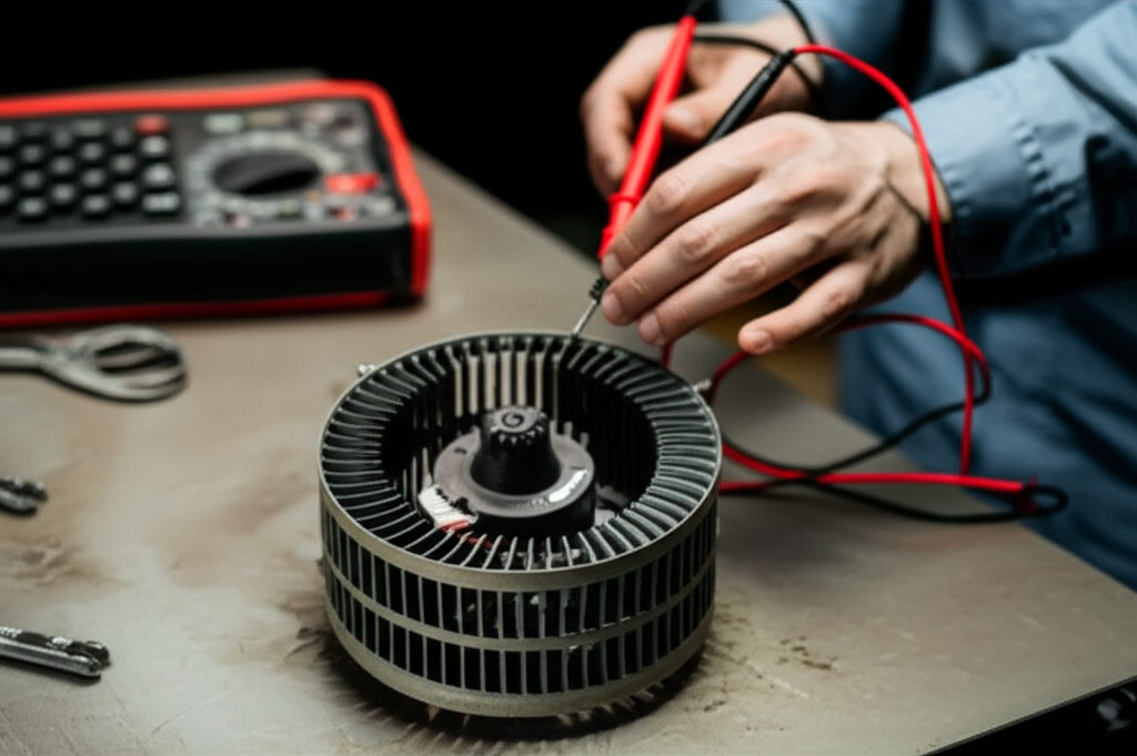
- Testing methods: Epstein frame testing and single-sheet testers measure core loss and magnetic properties. NVH testing under representative load profiles captures real acoustic behavior. Helium leak or electrical isolation tests can flag inter-lamination shorting in welded cores.
- Compliance and regulations: Ensure your adhesive systems and welding fume extraction meet local EHS rules. Maintain SDS documentation and ventilation plans.
What About the Stator vs. Rotor Decision?
Stators:
- Favor self-bonding when NVH and efficiency top your list. The damping and insulation benefits show up clearly in stator performance.
- If cycle time is a hard cap, integrate continuous curing and parallel buffering so you don’t pay a throughput tax.
Rotors:
- Favor welding when high RPM and mechanical stress dominate. You can still optimize weld patterns to limit added core loss.
- Validate dimensional stability. Add stress relief or post-processing if required to hit tight tolerances.
You can mix methods. Many EV motors use adhesive-bonded stators and welded rotors. It’s a smart split that balances performance and mechanical integrity.
Where the Lamination Itself Fits In
Your bonding choice plays out on a foundation built from good laminations. Material, thickness, and coatings drive your ceiling for magnetic performance and manufacturability. Learn more about electrical steel laminations and how grades and coatings affect core loss. If you’re designing a new stator stack, also review best practices for stator core lamination and how slot geometry, tooth tips, and insulating coatings play in the final TCO. For rotors, consider stress loading, skew, and balancing as you plan your rotor core lamination strategy.
Choosing the Right Method: A Decision Checklist
Use this checklist in your next design review:
- Motor type and application: EV traction, industrial drives, robotics, aerospace, or generators
- Performance targets: Efficiency, core loss, NVH, power density, thermal management
- Production volume and takt time: High-volume continuous flow or flexible medium-volume batches
- CapEx budget and ROI horizon: Payback windows and depreciation schedules
- OpEx drivers: Adhesive cost vs. welding energy and consumables
- Quality and scrap risk: Distortion risk vs. cure variability and delamination
- Design complexity: Very thin laminations, intricate slots, skew, or compact designs
- Maintenance and uptime: Equipment maintenance cadence and spare parts availability
- Supplier capability: Adhesive chemistry support, welder parameter development, and quality control
- Sustainability goals: Energy peaks, fumes, VOCs, and material waste
FAQs
What are the main advantages of self-bonding motor cores?
- Lower core loss and better NVH due to preserved insulation and damping
- Strong design flexibility for thin laminations and complex geometries
- Lower risk of distortion since there’s no localized melting
How does welding affect motor efficiency?
- Welds can form conductive bridges between laminations which may increase eddy current losses
- Smart weld patterns and reduced energy input can mitigate the penalty but rarely eliminate it
Is self-bonding suitable for all motor types?
- It fits most stators and many rotors. High-speed or high-stress rotors may still favor welding for mechanical strength
- Pick resin systems that match your operating temperature and environmental exposure
What is the typical lifespan difference?
- There’s no single rule. Adhesive-bonded stacks can match or exceed welded stacks in stators where NVH and insulation dominate. Welded rotors can outlast bonded ones under high centrifugal loads. Validate lifespan with application-specific testing
How do I reduce scrap and rework?
- For self-bonding: Calibrate adhesive coverage, verify cure, and tighten stack alignment
- For welding: Improve clamping, optimize parameters, and monitor HAZ and distortion
Your Engineering Takeaway
- Self-bonding often delivers the best TCO for stators that chase efficiency and quiet operation. It preserves lamination isolation and dampens vibration which cuts core loss and NVH.
- Welding delivers unmatched mechanical strength and short bonding cycles. It fits high-speed rotors and high-throughput lines when you can accept or mitigate added core loss.
- Don’t decide on equipment price alone. Model TCO across CapEx, OpEx, and lifecycle performance including energy, scrap, NVH, and warranty risk.
- Your material and design choices matter. Electrical steel properties, insulating coatings, lamination thickness, and stack geometry change the math.
- You can mix methods. Adhesive-bonded stators and welded rotors are common in high-performance motors.
Actionable next steps:
- Build a TCO model with your real volumes, labor rate, energy price, and scrap data
- Prototype both methods on the same lamination stack and measure core loss, NVH, and dimensional accuracy
- Use DFM to lock in weld locations or adhesive coverage early in design
- Qualify suppliers and run a pilot line to validate cycle time, maintenance cadence, and rework rates
- Document your ROI and risk assessment to support a long-term, defensible choice
If you want a quick refresher on stack fundamentals as you evaluate options, explore these resources on motor core laminations. They give helpful context on how material selection and stacking methods set the stage for performance and cost.
Trust signals and sources:
- IEC 60034 series for rotating electrical machines
- IEEE Transactions on Magnetics and IEEE Transactions on Industry Applications for peer-reviewed studies on core loss, bonding, and welding impacts
- ISO 3834 for welding quality requirements
- ASTM and ISO specifications covering electrical steels and insulation testing methods
Final note on data:
- The cost and performance ranges in this guide are illustrative. Actual values depend on your design, steel grade, adhesive chemistry, weld parameters, production scale, and local rates. Validate with trials and application-specific testing before you commit to a production path.