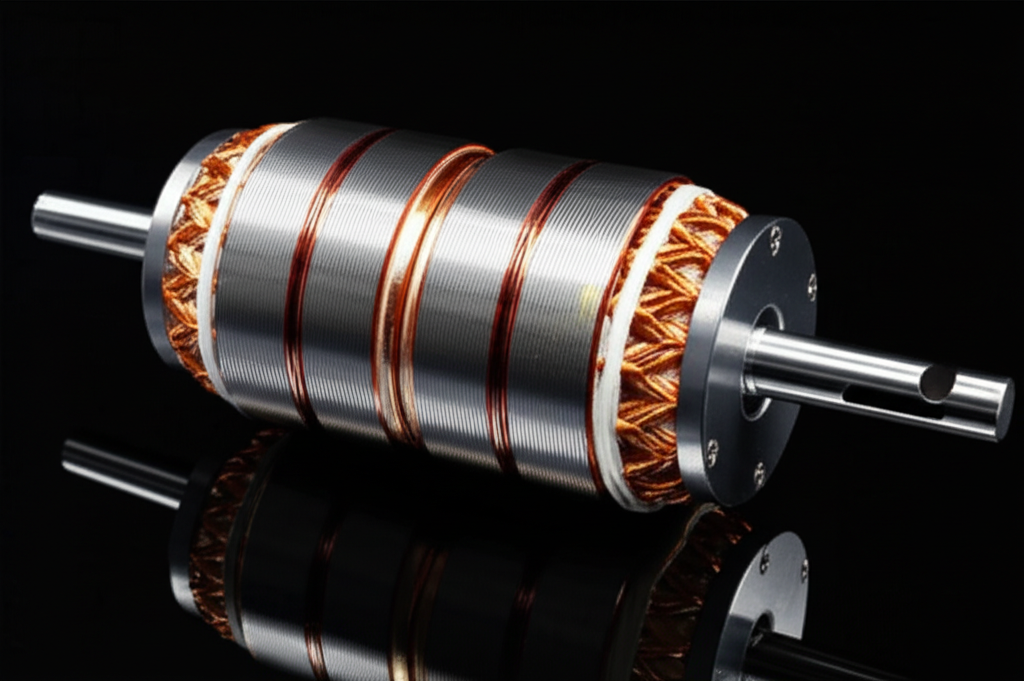
Stator vs. Rotor Skewing: Which Reduces Cogging Torque More? (Reddit’s Engineering Dilemma Answered)
Have you ever turned on a new fan or a drone and noticed a slight vibration or a humming noise? Or maybe you’ve felt a tiny “bump” or jerkiness when a motor starts up slowly. That annoying little problem has a name: cogging torque. It can make a smooth machine feel cheap and noisy. For engineers and hobbyists, it’s a constant headache. This article answers a big question we see all the time on places like Reddit: Should you skew the stator or the rotor to fix it? We’ll break it down in simple terms, so you can make the right choice for your project.
Table of Contents
- What is Cogging Torque and Why Should You Care?
- How Does Skewing Stop That Annoying Jerk?
- What is Rotor Skewing?
- What’s Good About Rotor Skewing?
- What’s Bad About Rotor Skewing?
- What is Stator Skewing?
- What’s Good About Stator Skewing?
- What’s Bad About Stator Skewing?
- So, Which is Better: Stator or Rotor Skewing?
- What Do Real Engineers Say? (Reddit’s Consensus)
- Are There Other Ways to Fix Cogging Torque?
- Where Does This Matter in the Real World?
- Key Takeaways
What is Cogging Torque and Why Should You Care?
Imagine you’re pushing a shopping cart with a wobbly wheel. It wants to “stick” in certain spots, right? You have to give it an extra push to get it rolling smoothly again. Cogging torque is just like that, but inside an electric motor.
In a Permanent Magnet Synchronous Motor (PMSM) or a Brushless DC Motor (BLDC), you have magnets on the spinning part (the rotor) and metal teeth on the part that stays still (the stator). The magnets are always trying to line up with the stator teeth, like tiny magnets snapping onto a fridge. This magnetic pull creates a bumpy, jerky feeling, especially when the motor is off or moving very slowly. This is also known as detent torque.
You might think a little bump isn’t a big deal. But it is. This tiny jerk causes big problems:
- Noise and Vibration: It’s the source of that annoying hum or buzz in many motors. This is a huge issue for quiet appliances, medical tools, and luxury electric vehicle (EV) motor noise. The main goal is often acoustic noise reduction in motors.
- Poor Control: For a robot arm or a camera drone, that jerk can ruin precision. You can’t have smooth, slow movements if the motor keeps sticking. This hurts improving low-speed performance.
- Wear and Tear: Constant vibration is bad for the motor’s parts. It can wear out bearings and other pieces over time, making the machine break down sooner.
So, this jerky feeling isn’t just annoying; it damages performance and can lead to failures. Fixing it is key to good motor design optimization.
How Does Skewing Stop That Annoying Jerk?
So how do we smooth out this bumpy ride? The most popular trick is called skewing.
Think about a car tire. A flat, smooth tire wouldn’t have much grip. But real tires have angled grooves. These grooves meet the road at different times, giving you a smooth, continuous grip. Skewing does the same thing for a motor.
Instead of having the magnets and stator teeth line up all at once, we twist them slightly. This is skewing. By twisting them, only a small part of the magnet is lining up with a stator tooth at any given moment. This spreads out the magnetic pull along the length of the motor. It averages out the “bumps,” making the rotation much smoother.
The trick is finding the perfect “twist” amount, which engineers call the skew angle calculation. Too little skewing and you still have bumps. Too much, and you can make the motor weaker. It’s a key part of the theoretical basis of skewing. Now, there are two main places to add this twist: on the rotor or on the stator.
What is Rotor Skewing?
The rotor is the part of the motor that spins. In a PMSM or BLDC motor, this is where the permanent magnets are.
Rotor skewing means the magnets themselves are twisted. There are a few ways to do this:
In both cases, you are changing the shape of the magnetic field so it interacts with the stator more smoothly. This is a very direct way to tackle the problem.
What’s Good About Rotor Skewing?
When I talk to engineers, many agree that rotor skewing benefits are significant if you can afford it. It’s one of the best cogging torque reduction methods available.
The biggest advantage is that it is often extremely effective. A well-designed skewed rotor can almost completely eliminate cogging torque. We’re talking reductions of 70% to 95%! This is why you see it in high-performance machines where smoothness is everything.
Another small benefit is that it can make the stator easier to build. Since all the complex twisting is on the rotor, the stator can be made with simple, straight slots. This can sometimes simplify one part of the manufacturing process.
What’s Bad About Rotor Skewing?
If rotor skewing is so great, why doesn’t every motor use it? As with most things in engineering, it comes down to trade-offs.
The main problem is the high manufacturing complexity of skewing the rotor. Making magnets with a special helical shape is very difficult and expensive. Even the “stepped” method requires very careful assembly to make sure all the small magnet pieces are lined up perfectly. This drives up the cost implications of skewing.
Another issue is a slight loss of power. When you skew the magnets, they aren’t perfectly aligned to produce power anymore. This can cause a small drop in the motor’s overall strength, what we call torque density reduction. You might see a 3% to 10% drop in average torque.
Finally, there is a very small demagnetization risk with skewing. The complex shape can create stress points in the magnets, which could cause them to lose a tiny bit of their magnetic strength over a long time, especially if the motor gets too hot.
What is Stator Skewing?
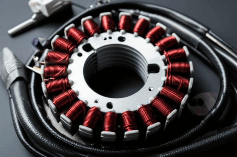
Now let’s look at the other option. The stator is the part of the motor that stays still. It’s a ring of metal with slots cut into it for the copper wires.
Stator skewing means that these slots are twisted along the length of the motor. Instead of going straight from front to back, they follow a slight angle. This is usually done by taking the stack of thin metal plates that make up the stator—the stator core lamination—and twisting the whole stack before it’s locked into place.
This has the same effect as rotor skewing: it staggers the point of magnetic attraction. As the straight rotor magnets spin past the twisted stator slots, the “bump” is smoothed out because the alignment happens gradually along the motor’s length.
What’s Good About Stator Skewing?
The stator skewing advantages are all about simplicity and cost. This is the big reason why it’s so common.
For companies that make millions of motors, stator skewing is much easier and cheaper to do. Stamping out thin metal plates is already part of the process. Twisting the stack before it’s welded or glued together is a relatively simple extra step. It doesn’t require special, expensive magnets.
Because of this, the cost implication is much lower. This makes it the perfect choice for cost-sensitive products like fans, pumps, and home appliances.
Also, stator skewing usually has a smaller impact on the motor’s peak power. The drop in average torque is often less than 5%, which is better than what you might see with rotor skewing.
What’s Bad About Stator Skewing?
Of course, stator skewing has its own set of problems.
The biggest challenge is the winding design impact. Winding copper wire into the stator slots is often done by fast, automatic machines. But these machines have trouble pushing wires into slots that are twisted. It can slow down production or require more expensive, specialized winding machines.
Also, while stator skewing is very good, it’s sometimes considered slightly less effective than a perfectly made skewed rotor. It can reduce cogging torque by 60% to 90%, which is great, but a perfectly made rotor might get you that extra 5% of smoothness.
Finally, if not designed well, the twisted slots can cause a little bit of magnetic field to “leak” out the ends, which can slightly increase core loss.
So, Which is Better: Stator or Rotor Skewing?
This is the big question. And the answer is: it depends on what you need. There is no single “best” choice for every motor. It’s all about balancing performance, cost, and how you plan to build it.
Here is a simple table to compare them, based on what we’ve learned from many academic studies on skewing:
| Feature | Stator Skewing (Twisted Slots) | Rotor Skewing (Twisted Magnets) | What This Means for You |
|---|---|---|---|
| Cogging Reduction | Very Good (60-90%) | Excellent (70-95%) | Rotor skewing can be slightly better, but both work well. |
| Cost to Make | Low to Medium | Medium to High | Stator skewing is almost always the cheaper option. |
| Difficulty to Make | Medium. Winding wires can be tricky. | High. Making and placing magnets is hard. | Stator skewing is easier for mass production. |
| Impact on Power | Small drop (0-5%) | Medium drop (3-10%) | Stator skewing usually keeps more of the motor’s power. |
| Best For… | Everyday motors (fans, pumps, appliances). | High-performance motors (EVs, robots). | Choose based on your budget and how smooth it needs to be. |
As you can see, it’s a classic engineering trade-off. If your main goal is to build a good, quiet motor at the lowest possible cost, stator skewing is probably your answer. If you need the absolute smoothest, highest-performance motor possible and cost is less of an issue, rotor skewing is the way to go.
What Do Real Engineers Say? (Reddit’s Consensus)
When you look at places like engineering forums motor discussion boards or electrical engineering Reddit threads, you see this debate all the time. The general feeling from people who build motors every day matches our table.
The consensus is this: start with stator skewing. It’s the industry standard for a reason. It’s a proven, cost-effective method that solves the problem for 90% of applications. Companies making things like appliance motor noise reduction a priority will almost always choose stator skewing. The design of the bldc stator core is critical to get this right.
However, for cutting-edge projects like automotive electric motors or high-precision robotics motor design, engineers are willing to pay for the extra performance of rotor skewing. They will use powerful computer programs for Finite Element Analysis (FEA) for cogging, like Ansys Maxwell or JMAG, to simulate and perfect the rotor magnet shape.
Are There Other Ways to Fix Cogging Torque?
Skewing is the most popular solution, but it’s not the only one! Engineers have a whole toolbox of tricks they can use, often combining them with skewing. These are considered other harmonic reduction techniques.
Some other methods include:
- Magnet Notching/Chamfering: Changing the shape of the magnet edges.
- Slot Opening Optimization: Making the opening of the stator slot wider or narrower.
- Fractional Slot Windings: Using a clever winding pattern that naturally cancels out some of the cogging.
- Magnet Shifting: Slightly changing the position of the magnets around the rotor.
Often, the best motor design optimization will use a combination of these. For example, a motor might use stator skewing and magnet chamfering to get excellent results at a reasonable cost. The choice of materials for the motor core laminations also plays a huge role in the final performance.
Where Does This Matter in the Real World?
You can find skewed motors everywhere. The choice between stator and rotor skewing has a real impact on the products you use every day.
- Electric Vehicles (EVs): Smoothness and quietness are key for a luxury feel. High-end EVs often use rotor skewing in their PMSM traction motors to give you that silent, instant acceleration without any vibration.
- Robotics and Drones: A robot arm needs perfect, smooth control. A drone motor cogging would make its video shaky. These often use rotor skewing for maximum precision.
- HVAC Systems: The fan motor in your air conditioner needs to be quiet. This is a perfect job for stator skewing, which provides great vibration reduction in motors at a low cost.
- Power Tools: A drill or saw needs to feel smooth and controlled. Many use stator skewing to reduce vibration, making the tool easier and safer to use.
From giant wind turbine generator cogging reduction to tiny motors in medical devices, choosing the right skewing method is a critical decision that affects performance, cost, and user experience.
Key Takeaways
To wrap it all up, let’s go over the most important things to remember from this guide.
- Cogging Torque is Bad: It’s a jerky, magnetic pull in motors that causes noise, vibration, and poor control.
- Skewing is the Solution: Twisting the stator slots or rotor magnets smooths out this jerky feeling.
- Stator Skewing is Cheaper: It’s easier to manufacture and is great for most everyday applications where cost is important. It’s the workhorse of the motor world.
- Rotor Skewing is Smoother: It can offer the absolute best performance and cogging reduction, but it costs more and is harder to make. It’s for high-end uses.
- It’s a Trade-Off: The right choice depends entirely on your project’s budget and performance goals.
- Always Simulate and Test: The best engineers use software and build prototypes to find the perfect design before mass production.
I hope this clears up the great stator vs. rotor skewing debate. Now you have the knowledge to understand why motors are designed the way they are and can make a smarter choice for your own projects.

