Stator vs. Rotor Core Lamination: My Experience and What I’ve Learned
Of course. Here is the article you requested.
When I first started working with brushless DC (BLDC) motors, I’ll admit, a lot of the internal components seemed like a complex puzzle. I knew there was a stationary part and a rotating part, but the nuances of how they were built and why they were different weren’t immediately obvious. The terms “stator core” and “rotor core” were thrown around, and they looked vaguely similar—both were stacks of thin metal plates. It took me a while, and a lot of hands-on experience, to truly grasp their distinct roles and the critical differences in their design and manufacturing.
If you’re in a similar boat, trying to understand what sets these two vital components apart, you’ve come to the right place. I’m going to walk you through everything I’ve learned about stator and rotor core laminations, breaking it down in a simple, straightforward way. We’ll cover what they are, what they do, and why their differences are so crucial for a motor’s performance.
Table of Contents
- What Are Motor Core Laminations Anyway?
- The Stator Core: The Motor’s Unmoving Foundation
- What is the Stator Core’s Job?
- Design and Construction of a Stator Core
- The Rotor Core: The Heart of Rotation
- What is the Rotor Core’s Job?
- Design and Construction of a Rotor Core
- Stator vs. Rotor Core: A Side-by-Side Comparison
- Why Materials Matter So Much
- The Role of Silicon Steel
- Thickness and Insulation
- How Manufacturing Differences Impact Performance
- Stamping and Stacking
- The Importance of Precision
- Real-World Impact: How Cores Affect Motor Behavior
- Efficiency and Heat
- Torque and Speed
- Noise and Vibration
- My Final Thoughts
What Are Motor Core Laminations Anyway?
Before we dive into the stator versus the rotor, let’s get a basic concept out of the way: lamination. Why are motor cores made of stacks of thin metal sheets instead of a solid block of iron?
It all comes down to fighting something called “eddy currents.” When you have a changing magnetic field interacting with a solid piece of metal (like a motor core), it induces small, swirling currents within the metal itself. Think of them like tiny whirlpools of electricity. These currents are bad news for motor efficiency. They don’t contribute to turning the motor; they just generate heat. A lot of it. This wasted energy is known as “core loss.”
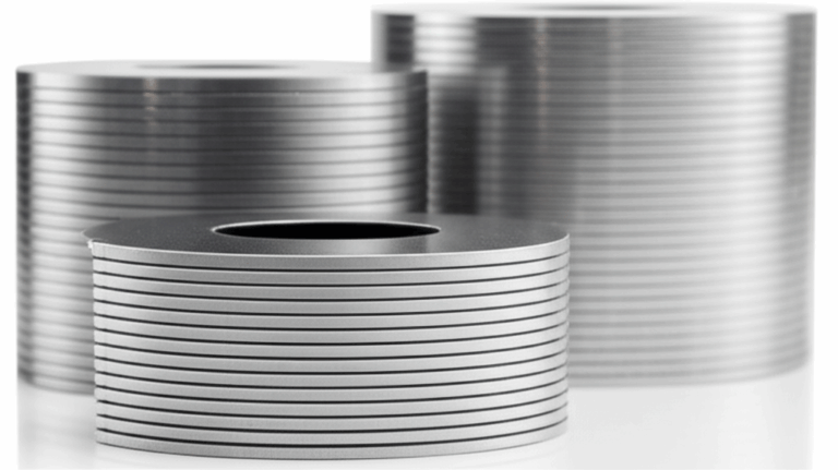
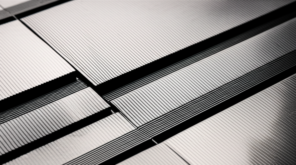
To combat this, engineers slice the core into very thin, insulated layers, or laminations. I remember the first time I saw a loose stack; it looked like a deck of weirdly shaped cards. Each of these thin sheets is coated with a varnish or an oxide layer that acts as an insulator. By stacking them together, you create a core that is magnetically conductive in one direction but electrically resistive in the other. This design effectively breaks up the paths for those wasteful eddy currents, forcing them into much smaller, less powerful swirls. The result? Significantly lower energy loss and a much cooler, more efficient motor.
So, whenever we talk about a bldc stator core or a rotor core, we’re almost always talking about a laminated structure. It’s a fundamental principle of modern motor design.
The Stator Core: The Motor’s Unmoving Foundation
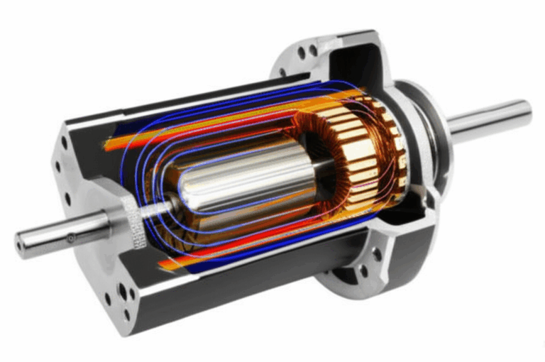
Let’s start with the stationary part of the motor: the stator. As its name suggests, the stator stays still. It’s typically the outer part of the motor that’s fixed to the motor housing. Its entire purpose is to create a powerful, rotating magnetic field.
What is the Stator Core’s Job?
The stator core is essentially the backbone for the motor’s windings. Think of it as a carefully designed frame with slots or teeth. Copper wires are wound around these teeth to form coils. When electricity flows through these coils, they become electromagnets. By precisely controlling the timing and direction of the current in different coils, we can create a magnetic field that spins around the central axis of the motor. This spinning field is what ultimately drives the rotor.
So, the primary job of the stator core is to concentrate and direct the magnetic flux generated by the windings. A well-designed core ensures that the magnetic field is strong and efficiently channeled to interact with the rotor.
Design and Construction of a Stator Core
When I look at a bare stator core, a few things stand out. First, it’s almost always a hollow cylinder with teeth pointing inward. These teeth create slots where the copper windings are inserted. The shape, size, and number of these slots are critical design parameters.
- Slot Design: More slots can allow for smoother operation and higher torque density, but they can also make the winding process more complex and expensive. The geometry of the tooth tips is also crucial for minimizing something called “cogging torque,” which is that bumpy, jerky feeling you can get when turning a motor by hand.
- Material: The material for a stator core lamination is almost universally a type of electrical steel, often a silicon steel alloy. This material is chosen for its excellent magnetic properties (high permeability) and low core loss characteristics.
- Stacking: The individual laminations are stamped out of large sheets of this electrical steel. They are then stacked together to form the final core height. This stacking process has to be incredibly precise. Any gaps or misalignment between the laminations can reduce the motor’s magnetic efficiency and increase losses. The stack is then held together, often by welding along the outside, cleating, or bonding with an adhesive.
The stator core is the powerhouse framework. It doesn’t move, but it’s responsible for creating the rotating magnetic field that makes everything else happen.
The Rotor Core: The Heart of Rotation
Now for the moving part: the rotor. If the stator is the frame, the rotor is the wheel that gets turned by the magnetic forces. It sits inside the stator (in an “inrunner” design) or revolves around the outside of the stator (in an “outrunner” design) and is connected to the motor’s shaft.
What is the Rotor Core’s Job?
The rotor’s job is to react to the stator’s rotating magnetic field and, in doing so, turn the shaft. In a brushless DC motor, the rotor core serves as the housing for powerful permanent magnets. These magnets are arranged with alternating north and south poles around the circumference of the rotor.
As the stator’s electromagnetic field rotates, it attracts and repels the permanent magnets on the rotor, pulling them along for the ride. This continuous magnetic chase is what creates the torque and rotation of the motor. The rotor core’s role is to provide a solid, magnetically efficient path for the flux from these permanent magnets, concentrating their field and ensuring it interacts effectively with the stator’s field.
Design and Construction of a Rotor Core
The construction of a rotor core can vary more than a stator core, depending on the type of BLDC motor.
- Surface-Mounted vs. Interior Magnets: In some designs (Surface Permanent Magnet or SPM), the magnets are simply glued to the outer surface of the rotor core. In others (Interior Permanent Magnet or IPM), slots are cut into the rotor core lamination stack, and the magnets are embedded inside. IPM designs are generally more robust at high speeds because they protect the magnets from being thrown off by centrifugal force.
- Material: Just like the stator, the rotor core is made from stacked laminations to minimize eddy current losses. Since the rotor is spinning within the stator’s magnetic field, it experiences a changing magnetic flux, which would induce significant currents in a solid core. The material is again typically a high-grade electrical steel.
- Mechanical Integrity: One thing I learned early on is that the rotor core has to be incredibly strong mechanically. It’s spinning at thousands, sometimes tens of thousands, of RPM. The lamination stack must be held together tightly—often through welding, riveting, or sometimes an interference fit with the shaft—to withstand the immense rotational forces without flying apart.
Stator vs. Rotor Core: A Side-by-Side Comparison
To make things crystal clear, let’s put the key differences side-by-side. I’ve found that a simple table can often clear up a lot of confusion.
| Feature | Stator Core | Rotor Core |
|---|---|---|
| Position | Stationary part of the motor, usually the outer frame. | Rotating part of the motor, connected to the shaft. |
| Primary Function | Houses the copper windings and creates a rotating magnetic field. | Houses the permanent magnets and transmits torque to the shaft. |
| Key Components | Slots/Teeth for copper windings. | Pockets or surfaces for mounting permanent magnets. |
| Magnetic Source | Electromagnetism (from current in the windings). | Permanent magnets. |
| Typical Shape | Hollow cylinder with internal teeth. | Solid or hollow cylinder, often with slots for magnets. |
| Main Stresses | Primarily thermal stress from winding heat. | Primarily mechanical stress from centrifugal forces. |
| Manufacturing Focus | Precision of slot geometry for winding and magnetic performance. | Mechanical strength and balance for high-speed rotation. |
Seeing it laid out like this really highlights how, despite being made of similar materials and processes, their jobs and design priorities are fundamentally different.
Why Materials Matter So Much
You can’t talk about motor cores without talking about the materials they’re made from. The choice of material is one of the most significant factors determining a motor’s overall performance and efficiency. It’s not just “iron”; it’s a very specific type of engineered steel.
The Role of Silicon Steel
I remember being surprised to learn that adding a small amount of silicon (usually up to 3%) to iron dramatically increases its electrical resistivity. As we discussed earlier, higher resistivity is great because it helps to reduce those pesky eddy currents. This is why most high-performance motor cores are made from electrical steel laminations, also known as silicon steel.
This material has another important property: low hysteresis loss. Hysteresis is a kind of magnetic “friction.” Every time the magnetic field in the core reverses (which happens thousands of times a second in a running motor), a little bit of energy is lost as heat. Special processing of the silicon steel minimizes this effect.
Thickness and Insulation
The thickness of the individual laminations is also a huge deal. Thinner is better for reducing eddy currents, especially at higher speeds and frequencies. You’ll often see laminations ranging from 0.2mm to 0.65mm. I’ve worked on projects where switching from a 0.5mm lamination to a 0.35mm lamination made a noticeable difference in reducing heat and improving efficiency.
Of course, thinner laminations are more expensive to produce and more difficult to handle and stack, so it’s always a trade-off between cost and performance. Each of these thin steel sheets also needs an insulating coating to prevent current from flowing between them. This coating is incredibly thin but absolutely essential for the whole lamination concept to work.
How Manufacturing Differences Impact Performance
The most perfectly designed stator or rotor core is useless if it’s not manufactured correctly. Precision is everything in this game. Small imperfections can lead to big problems in performance.
Stamping and Stacking
The most common method for creating laminations is stamping. A large press with a sharp die cuts the lamination shape out of a roll of electrical steel. This process is fast and cost-effective for high-volume production. For prototypes or specialized designs, laser cutting is often used, which offers more flexibility but is slower and more expensive.
Once the individual laminations are cut, they have to be stacked together. This can be done in a few ways:
- Welding: A bead of weld is run along the outer diameter of the stack. This is fast and strong but can create a short-circuit path for eddy currents right at the weld, which can increase losses slightly.
- Cleating or Interlocking: Some laminations are designed with small interlocking features that mechanically hold the stack together.
- Bonding: An adhesive is applied between the layers, and the stack is cured under pressure and heat. This often results in the best magnetic performance, as it provides excellent insulation between layers without the shorting effect of welding.
The Importance of Precision
I can’t overstate how important precision is. In the stator, the slot openings must be consistent so the windings fit perfectly. In the rotor, the magnet pockets must be precise to hold the magnets securely. Any imbalance in the rotor due to sloppy manufacturing will cause severe vibrations at high speeds. The air gap—the tiny space between the rotor and the stator—is often less than a millimeter. Maintaining this gap consistently is critical for performance, and it all comes back to the manufacturing tolerances of the stator and rotor cores.
Real-World Impact: How Cores Affect Motor Behavior
So, why do we obsess over all these details? Because the design and quality of the stator and rotor cores directly translate to how the motor performs in the real world.
Efficiency and Heat
A well-designed core made from high-quality, thin laminations will have low core losses. This means less energy is wasted as heat, and more of the electrical power is converted into useful mechanical work. In applications like electric vehicles or battery-powered tools, this is a massive deal. Better efficiency means longer range or longer runtime. It also means the motor runs cooler, which improves reliability and longevity.
Torque and Speed
The geometry of the stator teeth and the arrangement of the rotor magnets determine the motor’s torque characteristics. A design optimized for high torque will look different from one designed for ultra-high speeds. The core material’s ability to carry a high magnetic flux without saturating (becoming magnetically “full”) is key to producing powerful torque.
Noise and Vibration
Have you ever heard a cheap fan or motor that has an annoying hum or whine? A lot of that noise can be traced back to the motor cores. Imperfections in the lamination shape, poor stacking, or a design that isn’t optimized can lead to magnetic forces that cause the core to vibrate, creating audible noise. A precisely manufactured core with the right slot/pole combination results in a much quieter, smoother-running motor.
My Final Thoughts
When you look at a BLDC motor, it’s easy to just see a solid metal object. But I’ve learned that inside, it’s a finely tuned machine where every component plays a critical role. The stator and rotor cores, while seemingly just stacks of metal, are at the very heart of its operation.
The stator is the stationary foundation, using its carefully wound coils to create the spinning magnetic field. The rotor is the dynamic dancer, carrying the permanent magnets that are pulled along by that field to create motion. They are two halves of a whole, designed for different but complementary jobs. Understanding the distinction—why one is built for creating a field and the other for reacting to it, why one worries more about windings and the other about centrifugal force—is fundamental to understanding how these amazing motors work.
So next time you see a BLDC motor, remember the intricate, laminated structures inside. They represent a beautiful piece of engineering, where materials science and mechanical design come together to turn electricity into motion with incredible efficiency.