Optimizing SRM Lamination Stacks: The Critical Role of Tooth Shape in Noise Mitigation
Switched Reluctance Motors, or SRMs, are amazing. They are tough, reliable, and don’t cost a lot to make. But they have one big problem: they can be really noisy. If you’ve ever worked with one, you know what I mean. That loud hum and vibration can be a deal-breaker for many uses. This article will show you exactly where that noise comes from. More importantly, I’ll show you how a simple change in the shape of the motor’s “teeth” can make it whisper-quiet. Read on to learn the secrets of low noise SRM development.
Table of Contents
- Why Are These Super Strong Motors So Loud?
- What Are Lamination Stacks and Why Do They Matter?
- How Does the Tooth Shape Actually Make Noise?
- Can Changing the Stator Tooth Really Help?
- What About the Rotor Tooth? Does It Play a Part?
- Are There Secret Tricks for Shaping Teeth for Quiet Motors?
- What is a “Stepped Pole” and How Does It Stop Noise?
- What About “Chamfered” or “Slotted” Poles?
- Does the Number of Teeth on a Motor Matter for Noise?
- Is It Just the Teeth, Or Is There More to the Story?
Why Are These Super Strong Motors So Loud?
You have this great motor. It’s powerful and won’t break down. But when you turn it on, the acoustic noise is terrible. It creates so much switched reluctance motor vibration that it shakes the whole machine. This isn’t just annoying. This NVH, or Noise, Vibration, and Harshness, can cause parts to wear out fast. It can make a product feel cheap. In some cases, like in an electric car, a loud motor is simply not acceptable. The noise is a serious problem that can stop a great project in its tracks.
So, where does this racket come from? It’s not the bearings or a fan. The main source of noise in SRM motors is electromagnetism. Inside the motor, powerful magnetic fields turn on and off thousands of times a second. These forces pull on the steel parts of the motor. The main force is called radial force. Imagine a strong magnet pulling the motor’s shell outwards and then letting go, over and over. This makes the motor’s body bend and warp just a tiny bit. But when it happens thousands of times a second, it creates a sound wave. That’s the hum you hear.
There’s another force, too. It’s called tangential force. This is the force that makes the motor spin. But in an SRM, this force isn’t perfectly smooth. It has little bumps in it. We call this torque ripple. Think of it like pedaling a bike. If you push smoothly, the ride is smooth. If you stomp on the pedals, the ride gets jerky. Torque ripple is that jerky feeling, and it creates its own vibration and noise. Together, these forces are the root cause of magnetically induced vibration.
What Are Lamination Stacks and Why Do They Matter?
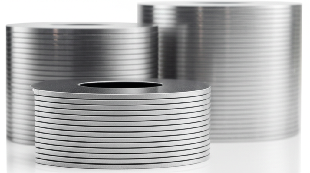
The heart of an SRM is the lamination stack. A motor isn’t made of solid blocks of steel. If it were, it would get very hot and waste a lot of energy. Instead, we use very thin sheets of a special metal called electrical steel. Think of it like a deck of cards. Each card is one sheet, or lamination. We stack hundreds of these sheets together to build the motor’s core. This structure is essential for controlling the magnetic fields and improving efficiency by reducing core losses.
The quality of this stack is super important for noise. The type of silicon steel laminations we use matters a lot. Some steels have better magnetic properties and can reduce something called magnetostriction, which is when the metal itself changes shape slightly when a magnetic field is applied. We also need to be very careful during the annealing process and when we assemble the stack. A tight, well-made stack with a high stacking factor helps to dampen vibration.
But the most important part of the lamination stack for noise is its shape. The stack is cut to have “teeth” or poles that stick out. You have the outer part, the stator core, which doesn’t move. And you have the inner part, the rotor core, which spins. The shape of the teeth on both the stator and rotor dictates how the magnetic field flows. And as we just learned, the magnetic field is what causes the noise. So, the shape is everything.
How Does the Tooth Shape Actually Make Noise?
It seems crazy that the shape of a metal tooth can make a motor loud or quiet, but it’s true. It all comes down to controlling the magnetic flux density. That’s just a fancy way of saying how strong the magnetic field is in a certain spot. When the rotor tooth moves past the stator tooth, the magnetic field jumps across the tiny space between them, called the air gap. The shape of the teeth controls how this jump happens.
If you have sharp, square corners on your teeth, the magnetic field gets squeezed and becomes very strong right at those corners. This is called magnetic saturation. When this happens, the magnetic forces become very spiky and uneven. These spikes in force are like little hammer taps on the motor’s structure, creating lots of vibration and noise, especially unwanted harmonics.
So, the goal of a good lamination stack design for noise is to make the magnetic field as smooth and even as possible. We want the force to build up gently and fade away gently as the motor spins. The shape of the tooth tips, the width of the teeth, and even the shape of the slots between them all change the air gap flux distribution. By carefully designing the lamination geometry, we can smooth out those forces and achieve significant SRM acoustic noise reduction.
Can Changing the Stator Tooth Really Help?
Yes, absolutely! The stator is the main source of the noise you hear because it’s the part that radiates sound into the air, like a speaker. Making small changes to the stator tooth geometry can have a huge effect. Let’s look at a few things we can change on the stator core lamination.
First, we can adjust the tooth width and the pole arc, which is how wide the tooth is at its tip. A wider tooth can handle more magnetic flux without hitting that nasty magnetic saturation point. This helps smooth out the radial forces. The shape of the tip is also critical. A perfectly flat tip can cause a very sudden change in force as the rotor passes by. By changing this shape, we can soften that transition.
Another key area is the slot opening between the teeth. This space holds the copper windings. The size and shape of this opening influence the path of the magnetic flux. Optimizing the slot-pole combination is a major part of noise reduction techniques in SRM design. By making smart choices here, we can directly influence the electromagnetic forcing function and reduce the vibration that makes noise.
What About the Rotor Tooth? Does It Play a Part?
The rotor is the other half of the puzzle. The shape of the teeth on the spinning rotor pole is just as important as the stator’s. The way the stator and rotor teeth line up is what creates the torque to make the motor spin. It also creates the torque ripple we talked about earlier. Fine-tuning the geometry of the rotor core lamination is a powerful tool for torque ripple mitigation.
Just like with the stator, the rotor pole arc and rotor tooth width are key design levers. The relationship between the stator pole arc and the rotor pole arc is especially important. This is called the pole arc ratio. Getting this ratio just right can dramatically smooth out the motor’s inductance profile. A smoother profile means a smoother pull from the magnets, which leads to less torque ripple and less noise.
We use powerful computer programs with Finite Element Analysis (FEA) to test these shapes. An FEA model lets us see the invisible magnetic fields inside the motor. We can see exactly where the forces are spiking. Then, we can perform a parametric study to change the tooth shape bit by bit until we find the quietest design without hurting the motor’s power. It’s a delicate balancing act, a multi-objective optimization problem, but it’s the key to high-performance, low-noise motors.
Are There Secret Tricks for Shaping Teeth for Quiet Motors?
You bet there are! Over years of research and testing, engineers have found some very clever ways to shape the teeth on core lamination stacks to fight noise. These aren’t just simple changes to width or height. They are advanced strategies that can cancel out or smooth the very forces that cause vibration. These methods are at the heart of modern low noise SRM development.
These techniques often focus on breaking up the sharp, sudden changes in the magnetic field. Instead of having one big “thump” of magnetic force as the teeth align, these designs create a series of smaller, softer “taps.” This spreads the force out over time and space, which is much easier on the motor’s structure and produces far less noise.
Think of it like this: jumping on a trampoline with stiff legs creates a big jolt. But if you bend your knees, you soften the landing. These advanced tooth shapes are like giving the motor’s magnetic field a set of knees to soften the impact. Let’s look at a few of the most effective strategies, like stepped poles, chamfered poles, and slotted poles. Each one offers a unique way to achieve passive noise reduction.
| Design Modification | Noise Reduction | Torque Ripple Reduction | Key Idea |
|---|---|---|---|
| Stepped Poles | 3-7 dB | 10-25% | Spreads magnetic force over time |
| Chamfered Poles | 2-5 dB | 5-15% | Softens corners to prevent force spikes |
| Slotted Stator Poles | 4-8 dB | 10-20% | Changes flux path to dampen vibration |
| Asymmetric Poles | 5-12 dB | Up to 25% | Cancels specific noise-causing forces |
What is a “Stepped Pole” and How Does It Stop Noise?
A stepped pole SRM design is a fantastic trick for radial force reduction. Instead of the tooth having one flat surface at the tip, we cut steps into it. So, as the rotor tooth comes around, it doesn’t align with the whole stator tooth at once. First, it aligns with the highest step. Then the next step, and then the next.
This simple change has a huge effect. It breaks that single, powerful magnetic pull into several smaller, weaker pulls that happen one after another. This staggered alignment smoothes out the change in force, which directly reduces the vibration that causes noise. The data shows that a stepped pole design can reduce the sound pressure level (SPL) by 3 to 7 decibels. That might not sound like a lot, but in terms of sound, it’s a difference you can easily hear.
We can put steps on the stator poles, the rotor poles, or both. The exact design requires careful analytical modeling to get the best results. But it is one of the most effective and proven methods for making an SRM quieter without hurting its power or efficiency too much.
What About “Chamfered” or “Slotted” Poles?
Chamfered poles are another simple but brilliant idea. A chamfer is just a small angled cut on the edge of the tooth. Instead of a sharp 90-degree corner, you have a soft, angled edge. Remember how those sharp corners cause magnetic saturation and force spikes? A chamfered pole motor solves that. The chamfer provides a smoother path for the magnetic flux, reducing that “hammer tap” effect and lowering the high-frequency harmonics that are especially annoying to the human ear.
Slotted stator poles are a bit more advanced. Here, we actually cut small slots or grooves into the face of the stator tooth. A slotted pole SRM uses these grooves to change the magnetic flux path and even alter the stiffness of the tooth itself. This can be used to target and dampen specific vibration modes of the stator. Think of it like a guitar string. If you put your finger on it, you change the note it plays. The slots act in a similar way, changing the “note” the stator wants to vibrate at, moving it away from the frequencies the motor is creating.
We can even use asymmetric pole designs. This is where we intentionally make the teeth on one side different from the other. It sounds strange, but this can be used to create forces that cancel each other out. It requires very precise FEA SRM noise simulation to get right, but it can lead to massive noise reductions of over 10 decibels for certain harmonics.
Does the Number of Teeth on a Motor Matter for Noise?
Yes, it matters a great deal! The number of teeth on the stator and rotor is called the slot-pole combination. A motor might be a “6/4” motor (6 stator teeth, 4 rotor teeth) or an “8/6” motor. This combination is one of the very first decisions an engineer makes, and it has a massive impact on the motor’s NVH characteristics.
Certain combinations naturally produce more torque ripple and more powerful radial force harmonics than others. The choice of pole count determines the fundamental frequencies of these forces. The real danger is resonance. Every object, including a motor stator, has natural frequencies at which it likes to vibrate. If the magnetic forces from the motor push on the stator at one of its natural frequencies, the vibration can become huge. It’s like pushing someone on a swing at just the right time to make them go higher and higher.
A big part of quiet SRM design is choosing a slot/pole number combination that avoids this. We perform a modal analysis on the lamination stack to find its resonance frequencies. Then, we choose a pole combination whose main forcing frequencies are far away from those danger zones. A good combination can be inherently quieter than a bad one, even before we start using advanced tooth shaping tricks.
Is It Just the Teeth, Or Is There More to the Story?
The tooth shape is the most powerful tool we have for designing quiet motor core laminations, but it isn’t the only one. For the very best results, we need a holistic approach that looks at the whole system. The best designs combine smart lamination geometry with other techniques.
For example, drive control strategies play a huge role. The way we send electricity to the motor’s windings can be changed to make the forces smoother. Techniques like current shaping and advanced Pulse Width Modulation (PWM) algorithms can actively work to reduce torque ripple and noise. This is called active noise control.
The physical structure around the motor also matters. A thicker stator back iron makes the stator stiffer, which can help avoid resonance. The housing design and the use of structural damping materials can absorb vibration before it turns into sound. Finally, using advanced materials like high-grade electrical steel laminations or even Soft Magnetic Composites (SMCs) can provide another small but important gain in noise reduction. By combining all these methods, we can build SRMs that are not just powerful and reliable, but also quiet enough for the most demanding applications.
Key Takeaways for a Quieter Motor
- The Problem: The main noise in SRMs comes from strong, pulsing magnetic forces (radial force and torque ripple) that cause the motor to vibrate.
- The Core Solution: The shape of the teeth on the lamination stack is the most critical factor in controlling these forces.
- Simple Fixes: Changing the pole arc ratio and tooth width can smooth out magnetic forces and reduce noise.
- Advanced Tricks: Using stepped poles, chamfered poles, or slotted poles are proven strategies to dramatically lower noise by spreading out or redirecting forces.
- Numbers Matter: Choosing the right slot/pole combination is essential to avoid dangerous resonance that amplifies vibration.
- A Full System Approach: For the absolute best results, combine smart tooth geometry with advanced motor controls and a robust structural design.