NVH Prediction Guide: Analyzing Stator Slotting and Rotor Magnet Forces in E-Motors
Have you ever driven in an electric vehicle (EV) and heard that high-pitched whine? It’s a sound that can cut right through the quiet cabin, making a high-tech car feel, well, a little cheap. That annoying sound is an NVH—Noise, Vibration, and Harshness—problem. As an engineer, you know that solving it is key to building a world-class EV. This guide is here to help. We’re going to break down exactly where that noise comes from, focusing on the two main culprits: the stator slots and the rotor magnets. You’ll learn how they “talk” to each other to create noise and, more importantly, how you can predict and stop it before it ever reaches the customer’s ears.
Table of Contents
- What Really Causes E-Motor Whine?
- How Do Stator Slots Make So Much Noise?
- What’s the Rotor’s Part in This Noisy Problem?
- Why is the Team-Up of Slots and Magnets So Bad?
- How Can We See a Noise Problem Before It Happens?
- What’s the Step-by-Step Plan for NVH Prediction?
- How Do We Fix Noise with Smart Stator Design?
- Can We Quiet the Motor by Changing the Rotor?
- What Are the Big Trade-offs We Have to Make?
- What Are the Main Things to Remember?
What Really Causes E-Motor Whine?
It all starts with invisible forces. Inside every electric motor, you have a spinning part (the rotor) and a still part (the stator). A powerful magnetic field flows across the tiny air gap between them. This field is what makes the motor turn. But here’s the catch: this magnetic field isn’t perfectly smooth. It pushes and pulls on the stator in a rapidly pulsing way. Think of it like tapping on a drum very, very fast.
These tiny pushes are called electromagnetic force harmonics. We can calculate them using a physics tool called the Maxwell stress tensor. The problem gets loud when the speed of this “tapping” matches a natural frequency of the stator. A natural frequency is a tone at which an object loves to shake. When the magnetic force harmonic hits that special frequency, it’s called resonance. This makes the stator vibrate like a bell, and that vibration travels through the motor housing vibration and into the air as that annoying EV motor whine. This is a big issue in any Permanent Magnet Synchronous Motor (PMSM), whether it’s an Interior Permanent Magnet (IPM) motor or a Surface Permanent Magnet (SPM) motor.
How Do Stator Slots Make So Much Noise?
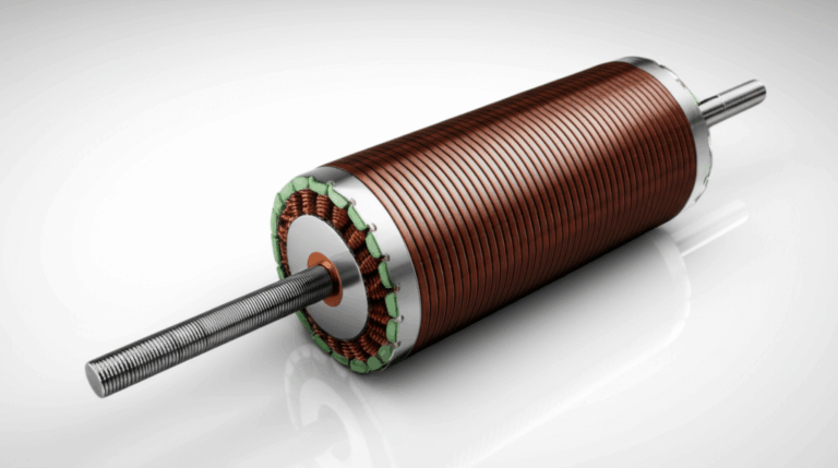
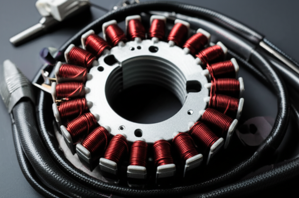
So, where do these pesky force harmonics come from? A big source is the stator itself. The stator isn’t a smooth ring; it has slots cut into it to hold the copper windings. These slots are essential, but they create a big NVH headache. As the rotor’s magnets spin past these slots, the magnetic field has an “uh-oh” moment. It’s easy for the field to cross the iron part of the stator (the “teeth”), but it’s hard to cross the open slot.
This change from easy to hard creates ripples in the magnetic field. We call these ripples permeance harmonics. Think of it like driving a car over a smooth road and then suddenly hitting a bunch of small, evenly spaced bumps. Those bumps are the slots. The permeance harmonics, or “slot harmonics,” are a major source of high-frequency noise in electric motors. This effect is a key part of the air-gap magnetic field modulation that every electric motor noise analysis must consider. A high-quality stator core lamination is the first step in controlling these effects.
What’s the Rotor’s Part in This Noisy Problem?
The rotor isn’t innocent, either. The neodymium magnets on the rotor create their own magnetic field, which we call the Magneto-Motive Force (MMF). In a perfect world, this field would be a beautiful, smooth wave—a perfect sinusoid. But in reality, it’s not. The shape of the magnets and their placement means the MMF has its own set of ripples, called MMF harmonics or rotor pole harmonics.
Several design choices affect these MMF harmonics. The magnet shape and the pole-arc ratio (how much of the rotor surface is covered by magnets) are huge factors. On top of that, tiny mistakes in manufacturing can lead to an Unbalanced Magnetic Pull (UMP). This is a net force that pulls the rotor to one side, causing a once-per-revolution vibration, much like an unbalanced tire on a car. And we can’t forget cogging torque and torque ripple. Cogging torque is that bumpy feeling you get when turning a motor by hand, and torque ripple is the fluctuation in torque as the motor runs. Both are low-frequency vibrations that you can often feel and hear.
Why is the Team-Up of Slots and Magnets So Bad?
This is where the real trouble begins. The stator slotting effect and the rotor magnet forces don’t just add up; they multiply. The final magnetic field in the air gap is a product of the rotor’s MMF harmonics and the stator’s permeance harmonics. When you multiply these two bumpy waves together, you get new, often much stronger, waves of force. It’s a classic case of two small problems combining to make one giant one.
Luckily, we can predict which of these new force harmonics will be the troublemakers. There’s a formula engineers use to find the force spatial order, which tells us the “shape” of the force wave pushing on the stator. By knowing the number of stator slots (Qs) and the number of rotor pole pairs (p), we can identify which harmonics are likely to cause a ruckus. This interaction is the heart of what makes predicting the e-motor acoustic signature so complex. The force decomposition shows us exactly how stator tooth harmonics and rotor harmonics create a new set of problems.
How Can We See a Noise Problem Before It Happens?
You wouldn’t build a bridge without a blueprint, and you shouldn’t build a motor without predicting its noise. The best tool we have for this is called a Campbell diagram. Imagine a chart. On the bottom axis, you have the motor’s speed, from zero up to its maximum. On the side axis, you have frequency, from low to high.
First, we do a structural modal analysis on the stator. This tells us its natural frequencies—the tones it likes to vibrate at. We draw these as straight, horizontal lines on our Campbell diagram. These are our danger zones. Then, we plot the electromagnetic force harmonics. These show up as diagonal lines that rise with motor speed. Any place where a diagonal “excitation” line crosses a horizontal “danger zone” line is a potential NVH hotspot. At that specific speed, the motor is likely to get very loud. This visual tool helps us spot risks long before we cut any lamination steel.
What’s the Step-by-Step Plan for NVH Prediction?
To make that Campbell diagram and really understand the noise, engineers follow a three-step multi-physics simulation workflow. It’s a digital journey from electricity to sound.
- Step 1: Electromagnetic Fun with FEA.
First, we build a digital twin of the motor in a Finite Element Analysis (FEA) software like Ansys Maxwell or Altair Flux. This 2D/3D FEA modeling solves Maxwell’s Equations to show us exactly what the magnetic field is doing inside the motor. The software then uses the Maxwell Stress Tensor to calculate the radial force density and tangential force density on the stator teeth. We use a Fast Fourier Transform (FFT) on these forces to see all the different force harmonics at play.
- Step 2: Seeing How the Stator Shakes.
Next, we take those forces and apply them to a structural model of the stator and motor housing, often in a tool like Simcenter 3D. We perform Modal Analysis to find the stator’s natural frequencies and mode shapes (how it bends and flexes). We look for common shapes like the oval (2,0) or triangle (3,0) modes, as these are easily excited. This step helps us understand if the stator yoke resonance or stator tooth resonance will be a problem.
- Step 3: From Shaking to Sound.
Finally, we do a vibro-acoustic simulation. We use the predicted vibration from the stator’s surface as the input. Using either the Boundary Element Method (BEM) or Finite Element Method (FEM) for acoustics, we model the air around the motor. The simulation then calculates how the vibration creates sound waves and predicts the Sound Pressure Level (SPL) in A-weighted decibels (dBA) at virtual microphone locations. This tells us just how loud the motor will be.
How Do We Fix Noise with Smart Stator Design?
Once we’ve predicted a noise problem, we can start designing a solution. The stator offers some powerful knobs to turn. The first is the slot-pole combination. Certain combinations of stator slots and rotor poles are naturally quieter than others. Choosing a good one is the first line of defense. For example, a Brushless DC (BLDC) motor might behave very differently with a different slot count. For a custom motor, the quality of the bldc stator core is critical.
Another trick is to optimize the stator slot opening. Making the opening smaller can smooth out the permeance harmonics, which can lead to a 3-6 dB reduction in high-frequency noise. However, this can also increase slot leakage flux, which might slightly hurt performance. A more advanced technique is using a Fractional-slot concentrated winding (FSCW). This special winding pattern can be designed to avoid creating specific, problematic harmonics. While it can cut noise by 5-10 dB, it might introduce other issues like sub-harmonics, so it’s a careful balancing act.
| Technique | How it Works | Typical Noise Reduction |
|---|---|---|
| Slot/Pole Combination | Avoids creating strong, low-order force harmonics. | Highly variable |
| Slot Opening Optimization | Smooths out the air-gap permeance variation. | 3-6 dB on specific harmonics |
| FSCW Windings | Changes the MMF harmonic spectrum to avoid problem areas. | 5-10 dB on dominant peaks |
Can We Quiet the Motor by Changing the Rotor?
Absolutely. The rotor is arguably the most powerful place to implement NVH mitigation techniques. The undisputed champion of noise reduction is rotor magnet skewing. This involves slightly twisting the magnets as they go down the length of the rotor. This simple change averages out the magnetic forces, smearing the sharp force harmonics into much weaker, broader ones. A skew of just one stator slot pitch can reduce the dominant noise harmonic by 5-15 dB and slash cogging torque by up to 90%. The trade-off? A small 1-3% loss in average torque and higher manufacturing cost.
We can also do pole shaping. Instead of using simple rectangular magnets, we can shape them—for instance, into a “bread-loaf” shape. This makes the rotor’s MMF waveform more sinusoidal, which reduces its harmonic content from the start. For IPM motors, a popular technique is using a V-shape magnet arrangement. By making the ‘V’ slightly asymmetric on alternating poles, we can cancel out specific torque ripple harmonics that cause low-frequency vibration. A high-quality rotor core lamination provides the precise geometry needed for these advanced techniques to work effectively.
What Are the Big Trade-offs We Have to Make?
As engineers, we know there’s no free lunch. Every decision we make is a balance. This is the world of e-machine design trade-offs. The fight between NVH vs. efficiency and NVH vs. torque density is constant.
For example, rotor skewing is fantastic for NVH, but it always comes with a slight torque penalty. Closing the stator slot openings helps with noise but might hurt efficiency by increasing flux leakage. Using an FSCW winding can solve one noise problem but might create a different torque ripple issue. This is why a thorough sensitivity analysis and parametric sweep analysis in your simulation software is so important. It lets you see how changing one parameter (like the skew angle) affects everything else (torque, efficiency, and noise). The goal is not to eliminate every vibration but to push the NVH problems out of the operating range where the driver will notice them, all while meeting your performance targets.
What Are the Main Things to Remember?
Tackling e-motor NVH can feel like a huge challenge, but it’s manageable when you break it down. It’s a journey from understanding the physics to making smart design choices, where every component, including the core lamination stacks, plays a role. Here are the key takeaways to guide you:
- Noise comes from interaction: High-frequency motor whine is primarily caused by the multiplication of magnetic ripples from stator slots (permeance harmonics) and rotor magnets (MMF harmonics).
- Prediction is key: Don’t guess. Use a multi-physics workflow (Electromagnetic -> Structural -> Acoustic) to predict noise problems early in the design stage. Tools like the Campbell diagram are your best friends.
- You have tools to fix it: You have a powerful toolkit of design solutions. On the stator, focus on the slot/pole count and slot opening. On the rotor, skewing and pole shaping are your most effective weapons.
- Everything is a trade-off: Be prepared to balance NVH, performance, and cost. A quiet motor that doesn’t meet its torque target isn’t a solution. Use simulation to find the sweet spot.