Motor vs. Engine Confusion Ends Here: A Practical Guide to Motor Laminations for Better Performance and Lower Cost
Every engineer has heard it. Someone says “engine” when they mean “motor,” or vice versa. The terms overlap in casual speech which causes confusion in design meetings. Yet the stakes feel higher when you’re choosing materials and processes for a stator or rotor stack that will decide your product’s efficiency, torque, noise, thermal behavior, and unit cost.
This guide tackles that head‑on. We’ll clear up the motor vs. engine distinction in simple terms. Then we’ll turn to what really moves the needle in electric machines: lamination material, thickness, insulation, and manufacturing processes. You’ll get an impartial breakdown of options with pros and cons. You’ll also get checklists you can use with suppliers today.
If you’re an engineer, product designer, or procurement manager who needs a clear path to “yes” on a motor core design that hits performance and budget targets you’re in the right place.
In This Article
- Why Motor vs. Engine Matters to Lamination Design
- Engineering Fundamentals: Eddy Currents, Hysteresis, and Core Loss
- Material Choices for Laminations and When to Use Them
- Manufacturing and Assembly Processes That Shape Performance
- Matching Solutions to Applications: EVs, Industrial Motors, High‑Frequency Drives
- Quality, Testing, and Specifications That De‑risk Your Program
- Procurement Playbook: Data to Request and How to Compare Quotes
- FAQs: Motors vs. Engines, Hybrids, and Common Terms
- Your Engineering Takeaway and Next Steps
Part 1: The Relatable Hook — Is This the Right Approach?
You want higher efficiency without blowing up cost. You need torque at low RPM yet you can’t add stack length. Your thermal model says core losses run too hot at your switching frequency. Or your stamping house quotes a longer lead time for a new grade you’ve never used.
All of these questions converge on one place. The lamination stack.
- How does lamination thickness affect eddy current loss and iron loss at your frequency
- Which electrical steel grades fit your B-H operating point with margin
- Should you stamp or laser cut for this geometry and volume
- What bonding or interlocking method gives you the stack factor and stiffness you need without hurting magnetic properties
- How do you specify coatings and insulation class so your stack survives impregnation and thermal cycling
If you’ve wrestled with any of these trade‑offs you’re asking the right questions. Let’s unpack the fundamentals so you can make clear, confident choices.
Why Motor vs. Engine Matters to Lamination Design
Let’s straighten out the terminology quickly because it frames the rest.
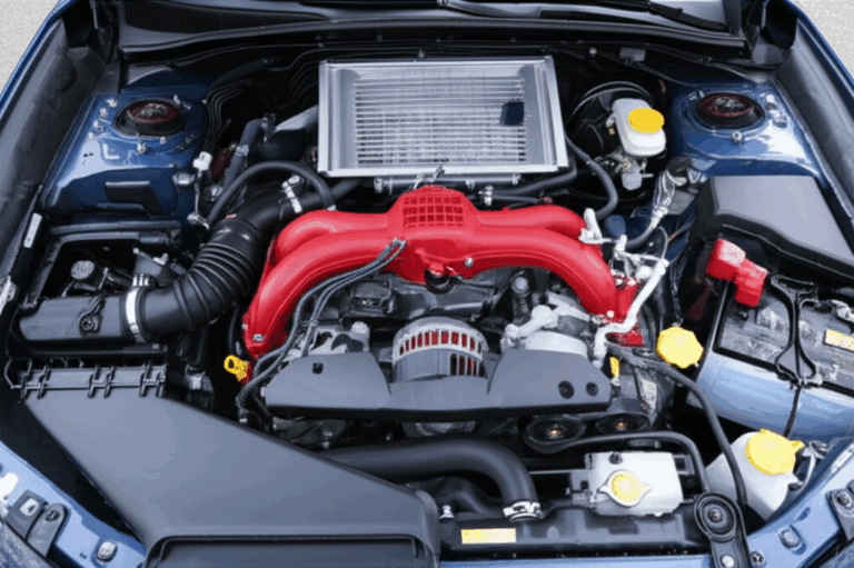
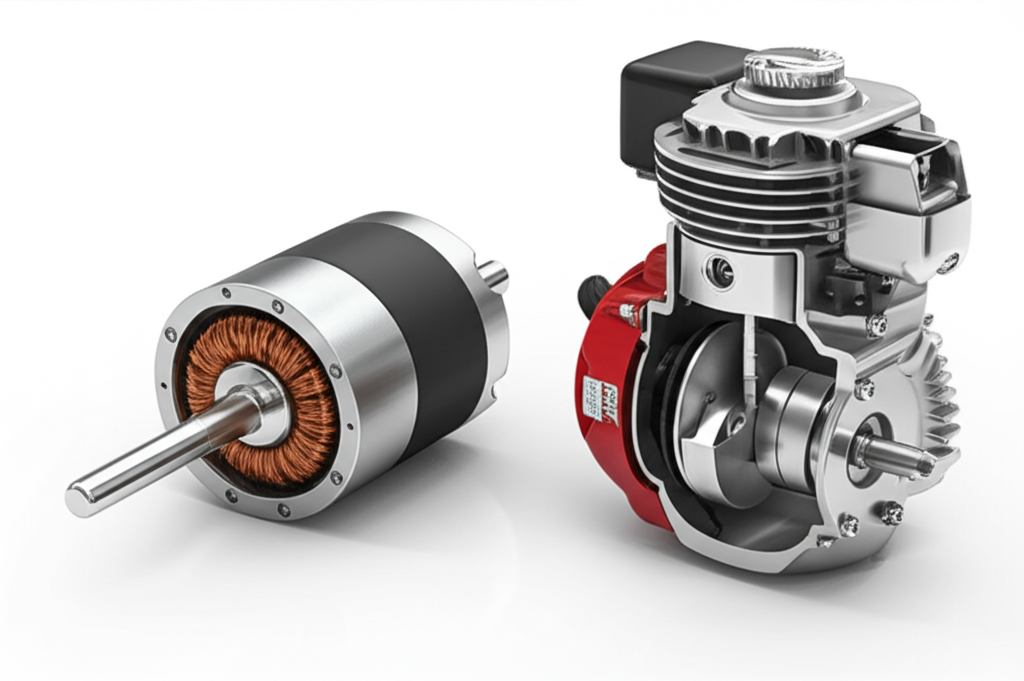
- Engine: A device that converts the chemical energy in fuel into mechanical energy. Internal combustion engines burn gasoline or diesel. Jet and rocket engines expel high‑velocity fluid for thrust. Engines convert chemical to thermal to mechanical energy. They produce direct emissions and significant heat.
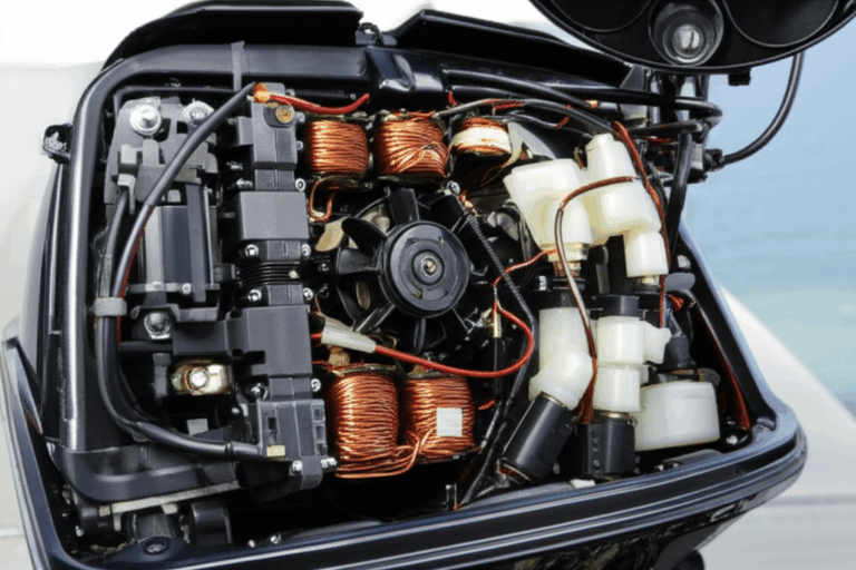
- Motor: A device that converts electrical energy into mechanical energy. Electric motors use electromagnetism. They convert electrical to magnetic to mechanical energy. They deliver instant torque from 0 RPM. They have zero tailpipe emissions at the point of use.
Both motors and engines deliver torque and horsepower yet the physics differ. You build a motor from magnetic circuits. Laminated steel cores steer magnetic flux in the stator and rotor. That’s why lamination choices dominate motor efficiency, noise, and thermal behavior. Engines use pistons, valves, and combustion chamber design. Laminations barely appear there except in alternators.
So when someone asks “What’s the difference between a motor and an engine” here’s the short answer engineers use:
- Motors run on electricity. Engines run on fuel.
- Motors use electromagnetism. Engines use combustion.
- Motors have zero tailpipe emissions. Engines emit CO2, NOx, and particulates.
- Motors are usually more efficient. Engines waste more energy as heat.
That’s the linguistic tangle untied. Now we can focus on the magnetic heart of electric machines.
Part 2: What’s Really Going On? The Engineering Fundamentals
At the core of every electric motor sits a flux path. You drive that flux with stator windings or permanent magnets. The steel in the path must guide the field well. It must also lose as little energy as possible while doing it.
Two loss mechanisms dominate in laminated steel:
- Eddy current loss: Changing magnetic fields induce circulating currents in the steel. Those little loops behave like tiny shorted turns. They generate heat and waste energy.
- Hysteresis loss: Magnetic domains resist changes in direction. Every magnetization cycle produces energy loss in the material. The area inside the B‑H loop equals that energy per cycle.
Here’s a simple analogy. Imagine a river with whirlpools. Eddy currents are the whirlpools. Thick solid steel lets big whirlpools form which means more turbulence and heat. Thin insulated laminations break those whirlpools into small eddies that die out fast. Less heat. Less loss.
Hysteresis loss behaves like friction in a hinge. If the hinge resists flipping directions you burn energy every time you swing it. A material with low coercivity flips more easily which cuts hysteresis loss.
Key ideas and terms worth defining in plain English:
- Magnetic permeability: How easily a material conducts magnetic field lines. Think of it like how easily a sponge soaks water.
- Saturation flux density (Bsat): The ceiling for magnetic flux a material can carry. Push past it and the material stops acting like a sponge and starts acting like a brick.
- Coercivity: How hard it is to demagnetize the material. Lower coercivity means less hysteresis loss.
- Core loss: The sum of hysteresis and eddy current loss at a given peak flux density and frequency. Suppliers usually quote W/kg at specified B and Hz using standardized tests like the Epstein frame per IEC 60404‑2.
- Stack factor: The ratio of steel thickness in a stack to the total stack height. Insulation and surface roughness reduce stack factor. Higher stack factor means more active steel in a given height.
Frequency and flux density set the stage. As frequency rises eddy current loss climbs fast because it scales roughly with thickness squared and frequency squared in simple models. Hysteresis loss scales roughly with frequency and with the shape of the B‑H loop. Designers juggle these effects when choosing grade and thickness.
Finally, the electric powertrain. Different motor topologies push different parts of the B‑H curve:
- Induction motor: Stator drives a rotating field. Rotor currents produce rotor flux. High slip at low speed. Torque builds with RPM. Common in pumps, fans, and compressors.
- Permanent magnet synchronous motor (PMSM): Magnets on the rotor provide constant field. Stator currents control torque. High efficiency and power density in EVs.
- Brushless DC motor (BLDC): Electronic commutation produces trapezoidal back EMF. Great for power tools and drones.
- Switched reluctance motor: Salient poles and variable reluctance deliver robust torque. Simpler rotor. Higher acoustic noise if not controlled well.
Regardless of topology the stator and rotor cores carry alternating flux. Laminations make or break performance.
Part 3: Your Options Explained — Materials and Manufacturing
You have two big levers. Material selection and manufacturing process. Each path comes with trade‑offs between efficiency, torque, noise, cost, and lead time.
Material Considerations
You’ll encounter these families again and again.
- Non‑oriented silicon steel (CRNGO): The generalist. It offers stable properties in all directions which suits motors with rotating fields. Grades vary by thickness and core loss. Typical thickness spans 0.50 mm to 0.20 mm. Thinner stock cuts eddy current loss at higher frequency.
- Grain‑oriented silicon steel (CRGO): Optimized for one direction which suits transformers more than motors. Great in stators with consistent flux direction if the design fits. Yields low core loss along the rolling direction.
- High‑silicon alloys: Higher silicon content improves resistivity and reduces eddy currents. It also reduces saturation flux density and increases brittleness which complicates forming.
- Cobalt‑iron alloys: High saturation flux density and good permeability at high frequency. They shine in high power density designs like aerospace actuators. They cost more.
- Amorphous and nanocrystalline metals: Very low core loss at high frequency due to random atomic structure and high resistivity. Great for high‑frequency transformers and specialized high‑speed motors. Forming and stacking can be challenging and costly.
What do you optimize for
- Efficiency of motors: Reduce total iron loss at your frequency and Bpeak. Thinner laminations and low‑loss grades help. So does operating below deep saturation.
- Torque motor response: Higher Bsat and permeability support torque density because the core carries more flux before saturation.
- Noise level motor: Materials with smoother magnetostriction behavior plus good mechanical stack integrity help lower vibration and noise.
- Thermal headroom: Lower loss means less heat generation. Better cooling and higher temperature insulation help reliability.
Helpful rule of thumb:
- High frequency or high inverter switching frequency favors thinner gauges.
- High torque density favors higher Bsat materials yet watch hystereses loss and cost.
- Cost sensitive, general purpose designs often land on CRNGO in a middle thickness.
Ask suppliers for core loss data at your operating points. Core loss curves at multiple B and Hz reveal how a grade behaves beyond a single spec point.
If you need an overview of common options start with electrical steel laminations. You’ll see how silicon steels, CRGO, and CRNGO map to typical motor and transformer needs.
Coatings and Insulation
Remember stack factor. You need electrical insulation between laminations to block eddy currents. Vendors apply inorganic or organic coatings. Each type has a temperature class, chemical resistance, and punchability profile.
- Thin inorganic coatings keep stack factor high. They suit high slot fill designs where space is tight.
- Organic coatings offer better corrosion resistance and may reduce burr welding during stamping.
- Some coatings tolerate welding and bonding adhesives better than others.
Match the coating to:
- Your impregnation resin chemistry.
- Your maximum winding or operating temperature.
- Whether you plan to weld, bond, or interlock.
- The desired stack factor and tolerance.
Grain Direction and Cutting Angle
CRGO shines along the rolling direction. If you ever use it in motors align your flux path to that direction. CRNGO is forgiving in any direction.
Stamping along the rolling direction reduces burr and improves magnetic performance. Laser cutting introduces a heat‑affected zone which can degrade magnetic properties near the cut edge. Post‑process annealing can recover performance in some materials if the thermal cycle fits.
Thickness and Frequency
Thinner laminations reduce eddy currents because they break up current paths more effectively. At 400 Hz you’ll likely choose 0.20 mm or thinner. At 50 or 60 Hz you can use 0.35 or 0.50 mm without heavy penalties. High‑speed motors and high switching frequency drives push you toward thinner stock and low‑loss grades.
Manufacturing and Assembly Processes
How you cut and stack laminations affects performance almost as much as the material.
- Progressive die stamping: Best for high volume and low piece cost. You get tight tolerances and repeatable burr control. Upfront tooling cost is higher.
- Laser cutting: Ideal for prototyping, short runs, and complex geometries. No tooling cost. Slower throughput. Heat‑affected zone must be managed.
- Wire EDM: Precise edges with minimal heat damage. Slow and best for tooling and special parts.
- Fine blanking: Produces clean edges and minimal burrs. Useful for medium to high volume with quality needs that exceed standard stamping.
- Post‑process annealing: Relieves stress from cutting and restores magnetic properties. Not all coatings survive it. Coordinate with your material and coating supplier.
Stacking and bonding methods decide mechanical integrity and influence magnetic behavior.
- Interlocking laminations: Tabs and notches form LEGO‑like joints. Good for throughput and avoids welding heat. It can increase local stress. It adds minor magnetic discontinuities at locks.
- Bonded stacks: Adhesive between laminations creates a solid core with excellent damping. It reduces noise and vibration. It keeps stack factor high if applied thin and uniformly. Adhesive choice must match temperature and chemical exposure.
- Welding: Spot or seam welding sets strong joints. Heat can degrade local properties and coatings. Use with care and plan for annealing if needed.
- Riveting and cleating: Mechanically simple and robust. May reduce stack factor slightly.
- Skewing: Skewed slots or rotor bars reduce cogging torque and acoustic noise. Manufacturing gets more complex and cost rises. Skew depth trades off with torque ripple and performance.
If you’re at the architecture stage this simple map helps. Use motor core laminations as the umbrella concept. Then decide how you’ll split requirements between the stator core lamination and the rotor core lamination.
Part 4: Matching Solutions to Applications
Now let’s go from theory to practice. Different sectors call for different lamination choices. We’ll keep it honest and practical.
Electric Vehicles and High Power Density Drives
- Goals: High efficiency across drive cycles. High torque at low RPM. Low noise. Tight packaging. Thermal robustness.
- Materials: Low‑loss CRNGO with thin gauges or cobalt‑iron for extreme power density. PM machines often benefit from high permeability stators. Rotors may use skew to reduce torque ripple.
- Frequency: Inverter switching frequency and electrical frequency rise at high speeds. Thin laminations mitigate eddy currents.
- Processes: Stamping with fine burr control for volume. Bonded stacks to damp noise. Rotor sleeve materials must handle centrifugal stresses and thermal growth.
- Trade‑offs: Cobalt alloys offer higher Bsat yet they cost more. You can sometimes reach targets with CRNGO plus optimization of slot geometry and cooling.
Industrial Motors for Pumps, Fans, and Compressors
- Goals: Reliability, efficiency at rated points, and cost control. Sometimes explosion proof or washdown duty.
- Materials: CRNGO in mid thickness is common. Optimize for 50/60 Hz with variable frequency drive operation.
- Processes: Progressive stamping for volume. Interlocks or bonding for robust stacks. Carefully manage burrs to limit stray losses.
- Trade‑offs: Thinner gauges cut losses at high VFD frequencies yet increase material and handling cost. Evaluate energy savings over life against upfront cost.
Robotics, Power Tools, and BLDC Applications
- Goals: Instant torque, rapid acceleration, compact size. Duty cycles vary widely.
- Materials: Thin gauge CRNGO or specialized high‑frequency materials for compact stators. Consider magnet grade for back EMF and thermal limits.
- Processes: Laser cutting suits fast iteration and complex topologies in prototyping. Move to stamping when volume stabilizes.
- Trade‑offs: Bonded stacks often reduce acoustic noise which matters in consumer devices. Adhesive selection must suit duty temperature and solvents.
Aerospace and Extreme Duty
- Goals: Maximum power density and efficiency under strict weight and temperature limits.
- Materials: Cobalt‑iron or advanced nanocrystalline in specialized cases. High Bsat helps torque density.
- Processes: Tight dimensional control with fine blanking or laser cutting plus post‑anneal. Bonded stacks for stiffness and damping.
- Trade‑offs: High material and process cost. Gains in power density and efficiency justify it when weight or endurance rules.
Transformers and Static Machines
Different problem yet the core ideas overlap. Grain‑oriented steels and EI/UI geometries dominate. If you cross over into that world you’ll look at transformer lamination core families like EI and UI for low loss at 50/60 Hz and beyond.
Motor vs. Engine: The Overlap and the Language
Why do people mix up motor vs. engine You see “motorcycle engine” which runs on fuel yet it gets called a “motor.” You also hear “motorboat” even though it uses an engine. Language evolves and sticks. In engineering you draw a clear line because it guides design decisions.
- Motor power source: Electricity from a battery or grid.
- Engine power source: Fuel like gasoline or diesel.
- Energy conversion in motors: Electrical to magnetic to mechanical.
- Energy conversion in engines: Chemical to thermal to mechanical.
- Emissions: Motors have zero tailpipe emissions. Engines emit CO2 and pollutants at the point of use.
- Noise and vibration: Motors are quieter and smoother. Engines shake more due to combustion.
- Maintenance: Motors have fewer moving parts. Engines need oil changes and filters.
This matters in procurement because the whole bill of materials changes with the power source. An engine adds fuel tanks, exhaust systems, and emissions control. A motor adds power electronics, batteries, cooling, and safety systems. Laminations sit at the center of motor design because they steer magnetic flux. Engines don’t rely on laminated cores except in alternators and starters.
Part 5: Quality, Testing, and Specifications That De‑risk Your Program
You reduce risk with clear specifications and standard test methods. Start with these anchors.
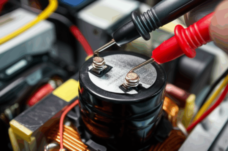
- Material testing:
- Core loss and permeability: Use standardized methods like the Epstein frame per IEC 60404‑2. Ask for W/kg at your target B and Hz not only at catalog points.
- B‑H curve data: Request curves to your expected peak flux density. Confirm coercivity and Bsat.
- Coating: Request insulation class, thermal rating, and compatibility data with your impregnation resin.
- Machine testing:
- Efficiency and torque: IEEE Std 112 covers polyphase induction motor testing. For other topologies align to IEC 60034 series for rotating electrical machines.
- Noise and vibration: Specify test setups and acceptance limits. Bonded stacks often help.
- Dimensional control:
- Stamping burr limits: Define max burr height and direction. Burrs add stray losses and can damage insulation.
- Stack factor: Specify minimum stack factor and measurement method.
- Skew angle control: Define tolerances for skewed stacks.
- Process control:
- Annealing cycle: Define when and how to anneal if you laser cut or weld. Protect coatings and insulation.
- Adhesive process: Define cure profile and bond line thickness if you bond laminations.
- Cleanliness: Specify allowed contamination levels and protective oils compatible with downstream processes.
Suppliers will recognize these references. Your drawings and purchase specs should point to recognized standards like IEC 60034 for motors and IEC 60404 for magnetic materials. That keeps interpretation consistent.
Procurement Playbook: What to Ask and How to Compare
When you request quotes make it easy for suppliers to give accurate pricing and practical lead times.
Send:
- 2D drawings for laminations with material callouts, thickness, coating, grain direction, and burr limits.
- 3D model or section views for the stator and rotor stack. Include skew and interlock details if any.
- Stack height, stack factor target, and assembly method.
- Expected volumes and ramp plan. Stamping dies justify cost at volume. Laser suits prototypes.
- Target performance: Operating frequency, Bpeak, and acceptable core loss at key points. Suppliers can propose grade alternatives that hit these targets.
- Environmental and process constraints: Max operating temperature, chemical exposure, thermal cycles, and impregnation resin.
Compare:
- Material grade and thickness options with W/kg at your operating conditions.
- Coating type and thickness with stack factor impact.
- Process route: Stamping vs. laser vs. fine blanking. Upfront tooling cost and piece price.
- Post‑processing: Annealing needs and coating survivability.
- Quality plan: SPC on critical dimensions, burr measurement method, and sample test reports.
- Lead time and capacity: Tooling build time and weekly output at your target volume.
You’ll often see one quote with low piece price and high tooling cost for stamping and another with higher piece price and near zero tooling for laser. Map these to your ramp plan. Prototype fast with laser then switch to stamping when design freezes.
Practical Design Tips You Can Use Today
- Control your flux density. Operate with margin below saturation because it reduces hysteresis loss and keeps inductance stable under load.
- Match thickness to frequency. If you drive high electrical frequency or high PWM frequency choose a thinner gauge to cut eddy currents.
- Mind the edges. Burrs and heat‑affected zones increase local losses. Use fine blanking or post‑anneal laser cuts when the budget allows.
- Pick coatings for the whole lifecycle. Consider punching, bonding, welding, impregnation, and thermal cycling.
- Think about cooling early. Lower core loss reduces heat. Better cooling buys margin for copper loss and torque peaks.
- Reduce noise at the source. Bonded stacks damp vibration. Skew reduces cogging torque. Smooth magnetostriction helps.
Frequently Asked Questions
Q: Is a car’s powertrain an engine or a motor
A: Gasoline and diesel cars use an internal combustion engine. Hybrid electric vehicles use both an engine and one or more electric motors. Battery electric vehicles use motors only.
Q: Can an engine be called a motor
A: In casual speech yes. In engineering use “engine” for fuel‑powered machines and “motor” for electrical machines. Clarity helps avoid design and procurement mistakes.
Q: Do electric cars have engines
A: No. They have one or more electric motors. Those motors have stators, rotors, stator core lamination stacks, and power electronics instead of pistons and exhaust systems.
Q: Which is more efficient, a motor or an engine
A: Electric motors often achieve 70 to 95 percent efficiency depending on type and duty. Internal combustion engines usually land around 20 to 40 percent. Motors waste less energy as heat at the point of use.
Q: What about a “motor boat”
A: The name stuck from early usage. Many motorboats use engines. Some use electric motors. Use the technical term in specs to avoid confusion.
Q: How do lamination thickness and material grade affect my efficiency
A: Thinner laminations reduce eddy current loss at higher frequency. Low‑loss grades cut hysteresis loss. Both reduce core loss which raises efficiency and lowers operating temperature.
Q: Should I stamp or laser cut my laminations
A: Stamp when you need high volume and low piece cost. Laser when you prototype or build low volumes with complex shapes. You can post‑anneal laser‑cut parts to recover magnetic properties.
The Motor Core in Focus: Stator vs. Rotor
You design the stator and rotor differently because they see different fields and mechanical loads.
- Stator:
- Carries alternating flux at line or inverter frequency.
- Houses windings or concentrated coils. Insulation and slot liners matter.
- Needs tight slot geometry for slot fill and thermal paths.
- Often benefits from bonded stacks to reduce vibration and noise.
- Rotor:
- Sees rotating fields and significant mechanical stresses from centrifugal force.
- In PM machines the rotor adds magnets and sleeves. Lamination properties influence leakage and eddy currents from slotting and harmonics.
- In induction motors the rotor bars and end rings introduce additional loss and thermal considerations.
- Skew may be applied to reduce torque ripple.
Tie both together and you get a magnetic circuit that sets torque and power. Small changes in tooth width, yoke thickness, and stack height swing performance. The lamination stack is not a commodity part. It’s the backbone of your magnetic design.
Environmental and Regulatory Considerations
- Emissions: Electric motors produce zero tailpipe emissions at the point of use while engines produce exhaust gases like CO2, NOx, and particulates. Grid emissions depend on power source.
- Noise and vibration: Motors are quieter than engines. You still need to manage acoustic targets. Lamination bonding and skew help.
- Efficiency standards: Grid connected motors may fall under regional efficiency regulations. Higher efficiency pays back in energy savings across the product life.
Trust Signals and Sources You Can Use
- IEC 60034 series: Rotating electrical machines. Covers ratings, performance, and testing for many motor types.
- IEC 60404‑2: Magnetic materials testing by Epstein frame. Use it to compare core loss data across suppliers.
- IEEE Std 112: Test procedures for polyphase induction motors and generators.
You can cite these in specifications and quality plans. They give you common ground with suppliers and test labs.
Your Engineering Takeaway
Here are the key points to keep in your notebook.
- Use the right words. Motors convert electrical energy to mechanical energy using electromagnetism. Engines convert chemical energy to mechanical energy using combustion. That distinction matters when you spec parts.
- Core loss is the enemy. Eddy currents and hysteresis heat your stack and cut efficiency. Thinner laminations and low‑loss grades fight that.
- Thickness tracks frequency. Higher electrical frequency pushes you toward thinner laminations.
- Material choice sets the ceiling. Permeability and Bsat dictate how much flux your steel carries before saturation. That sets torque density limits.
- Manufacturing matters. Stamping, laser cutting, and post‑anneal change magnetic properties and cost. Bonding, interlocking, or welding change stack integrity, noise, and stack factor.
- Specify clearly. Call out material grade, thickness, coating, burr limits, stack factor, skew, and test methods. Ask for core loss at your B and Hz.
- Match solution to duty. EVs and high power density drives justify thin gauges and advanced alloys. Industrial motors often balance cost and efficiency with CRNGO in mid thickness.
- Bring suppliers in early. Share duty cycles and thermal models. Good partners will propose material and process tweaks that save money without hurting performance.
Empowered Next Steps
- Map your operating points. List your electrical frequency range, inverter switching strategy, peak flux density, and duty cycle. This frames your material and thickness choices.
- Shortlist materials. Request core loss curves at your B and Hz for two or three candidate grades and thicknesses. Compare efficiency and cost.
- Choose a process path. Prototype with laser or fine blanking. Plan for stamping when volumes justify tooling. Decide on bonding vs. interlock with noise and stack factor in mind.
- Lock down specifications. Add IEC 60404‑2 for material testing and IEC 60034 references for machine testing to your drawings and purchase orders. Specify burr limits and stack factor.
- Engage a lamination specialist. Share your 2D lamination drawings and a 3D stack model. Ask for DFM feedback on slot geometry, burr control, and coating choice.
If you want a quick orientation across parts and assemblies browse these resources:
- Overview of electrical steel laminations
- System view of motor core laminations
- Stator‑specific considerations in stator core lamination
- Rotor design trade‑offs at rotor core lamination
You now have a clear line between motors and engines. You also have a structured way to choose lamination materials and processes that move your design forward. When you face the next trade study ask what problem you must solve first. Then use these fundamentals to explain, guide, and decide with confidence.