Motor vs. Engine: Are They the Same? What Engineers Need to Know—Plus How Laminations Shape Performance
You hear it all the time. “What engine powers that EV?” or “Does that generator use a motor?” In casual talk the words motor and engine get swapped without much thought. In engineering and manufacturing those words carry weight. They signal different energy conversion principles, component sets, and design constraints. If you spec parts, design machines, or source laminated cores, the distinction is more than semantics. It affects efficiency, emissions, maintenance, cost, and how you structure a supply chain.
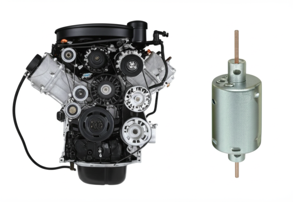
Short answer to the big question: a motor and an engine are not the same thing. People use them interchangeably in day‑to‑day speech. Engineers don’t. Engines convert chemical or thermal energy into mechanical work through combustion or a thermodynamic cycle. Motors convert electrical energy into mechanical work through electromagnetism. That difference drives everything from powertrain design to lamination material choice.
Now here’s where your world comes in. Electric motors live or die by their magnetic cores. Rotor and stator laminations sit at the heart of torque production, efficiency, and thermal behavior. If you care about lower losses, quieter operation, and a power‑dense package, you care about laminations.
Below, I’ll clear up the motor vs engine confusion. Then I’ll walk you through the core physics, materials, and processes behind high‑quality motor laminations. You’ll leave with a practical checklist and the confidence to make the right trade‑offs for your application.
In This Article
- The Fundamental Difference: Motor vs Engine
- Why Lamination Material Choice Is Critical in Motors
- Understanding Core Losses: Eddy Currents and Hysteresis
- A Guide to Common Lamination Materials
- Key Manufacturing Processes and Their Impact
- Which Application Is This For? Best‑Fit Recommendations
- Quick Comparison: ICE vs Electric Motors for Decision‑Makers
- Procurement Checklist and Risk Mitigation
- Your Engineering Takeaway
The Fundamental Difference: Motor vs Engine
Let’s get precise.
- Motor defined: A motor converts electrical energy into mechanical energy. It uses electromagnetism to produce torque at a rotor from current in a stator. Electric motors show up in EVs, industrial drives, fans, pumps, compressors, and robots. They can be AC motors like induction or synchronous designs. They can be DC motors like brushed, brushless, servo, or stepper types.
- Engine defined: An engine converts chemical energy in fuel or thermal energy from steam into mechanical energy. It relies on combustion or thermodynamic cycles. Internal combustion engines burn gasoline or diesel inside cylinders with pistons and a crankshaft. Jet engines compress and combust air for thrust. Steam engines and Stirling engines use external heat sources.
Key distinctions at a glance:
- Power source: Motor uses electrical energy. Engine uses chemical or thermal energy.
- Operating principle: Motor relies on electromagnetism. Engine relies on combustion or thermodynamics.
- Emissions: Motors have zero tailpipe emissions. Engines produce CO2, NOx, PM, and VOCs at the point of use.
- Starting: Motors start instantly with current. Engines need ignition and a starting mechanism.
- Complexity: Motors use fewer moving parts. Engines have pistons, valves, fuel injectors, spark plugs, exhausts, lubrication systems, and more.
- Efficiency: Motors typically reach 85–95% peak efficiency. Gasoline engines often land near 20–40% under peak conditions. Diesel engines run a bit higher under peak loads.
- Noise and vibration: Motors run quieter with less vibration. Engines generate combustion noise and mechanical vibration that demands isolation and damping.
- Maintenance: Motors often need bearing checks and cooling system service. Engines demand oil changes, filters, plugs or injectors, and periodic overhauls.
So why the confusion? History. “Engine” once meant any device that produced force or work. James Watt drove steam engine adoption. Nikola Tesla revolutionized electric motors and power systems. Karl Benz and Rudolf Diesel made the internal combustion engine the backbone of mobility. Over time “engine” became strongly associated with fuel and combustion. “Motor” became the word for electricity‑driven machines. Today both are prime movers. Only one needs laminations to slash eddy currents.
Why Lamination Material Choice Is Critical in Motors
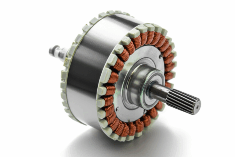
If a motor is your prime mover, laminations are the bones and blood of its magnetic circuit. The stator core channels magnetic flux. The rotor core closes the flux path and carries induced currents or magnetic poles. Together they turn electrical energy into torque.
Here’s the physics in a nutshell. Alternating magnetic fields inside the core induce circulating currents in the steel. Those are eddy currents. They waste power as heat. They also raise temperature, which raises core losses further, which steals efficiency and torque. Laminations fight those losses. Thin sheets of electrical steel are stacked with insulation between layers. Insulation breaks up the current loops which starves eddy currents. Thinner laminations reduce loop area and cut loss. The trade‑off shows up in cost, stack factor, and manufacturability.
Material choice sets magnetic permeability, saturation flux density, coercivity, and resistivity. Those knobs control hysteresis and eddy current losses across your operating frequency. The right grade and thickness can lift efficiency points and lower your thermal budget. That ripple lets you downsize cooling, increase continuous torque, or reduce copper mass. Real money moves there.
For a quick overview of part families and geometry impacts, see modern motor core laminations. You’ll see why slot count, tooth width, back iron thickness, and stack height all thread the same needle. Flux density in the teeth and yoke drives both torque and loss. Geometry and material must work together.
Understanding Core Losses: Eddy Currents and Hysteresis
Think of eddy currents as tiny whirlpools in water. A changing magnetic field flows through a steel riverbed. Without barriers those whirlpools get big and strong. They churn energy into heat. Laminations act like gravel bars that break the water into many smaller currents which reduces turbulence and slows energy loss.
Two major loss mechanisms drive your core thermal profile.
- Eddy current loss: Proportional to frequency squared, lamination thickness squared, and roughly to the square of peak flux density. Double the frequency and eddy loss jumps by four. Go thinner on laminations and you shrink loops which cuts loss sharply. Insulation class and coating uniformity matter because pinholes and scratches create shortcuts for current.
- Hysteresis loss: Proportional to frequency and depends on the material’s B‑H loop area. It is tied to coercivity which is the resistance to magnetization reversal. Materials with low coercivity have narrow B‑H loops and lower hysteresis loss.
Three more levers influence both:
- Temperature: Magnetic properties drift with heat. Loss rises as resistivity and permeability change. Better cooling buys margin.
- Flux density: Running closer to saturation boosts torque per mass, yet loss and local heating climb. You must size back iron and teeth to hit targets without saturating large regions.
- Waveform: PWM switching creates harmonic content that elevates high‑frequency loss. The effect grows in high‑switching drives used by EV inverters and industrial variable frequency drives.
On the motor performance side, these losses show up as:
- Higher stator and rotor temperature.
- Lower sustained torque production and peak power.
- Audible noise from magnetostriction and ripple torque.
- Efficiency hits that raise cost per kilowatt‑hour in stationary power and reduce range in EVs.
The antidote is simple in concept and nuanced in practice. Use the right grade and thickness. Use the right insulation coating. Use a process that minimizes burrs and residual stress. Then validate the stack with a core loss test at your operating flux density and frequency.
If you are new to the magnetic terms, a few quick definitions help:
- Magnetic permeability: How easily a material carries magnetic flux. Picture it like a sponge soaking up water.
- Coercivity: The field strength needed to demagnetize the material. Lower is better for low loss.
- Saturation flux density: The point where more magnetizing force produces only small increases in flux. Hit it and torque stops scaling cleanly.
A Guide to Common Lamination Materials
Electric motors lean on electrical steels with tailored silicon content and carefully controlled grain properties. Your choice depends on frequency, flux density, thermal environment, size, and cost target.
Silicon steels (non‑oriented and grain‑oriented)
- Non‑oriented electrical steel (CRNGO): Silicon content improves resistivity and reduces losses. Non‑oriented sheet offers similar magnetic properties in all directions. It fits rotating machines like induction and permanent magnet motors. You will see grades often identified by numbers like M19 or M27 in the market. Lower numbers tend to indicate lower loss at a reference condition.
- Grain‑oriented electrical steel (CRGO): Optimized for one direction. It shines in transformers and some specialized axial flux configurations that align flux paths with the rolling direction. Most rotating motors prefer non‑oriented grades because flux rotates through many angles.
Cobalt‑iron alloys
- Cobalt alloys boost saturation flux density. They allow higher torque density and better performance at elevated temperatures. Aerospace and high‑speed machinery that values high power density lean on these. The downside is cost which is high. Machining and supply volatility require careful planning.
Low‑carbon steels
- Low‑carbon steels without silicon trade higher losses for lower price. They appear in low‑frequency or low‑duty applications where cost drives everything. Be careful with heat rise and efficiency expectations.
Specialized coating systems
- Coatings provide electrical insulation between laminations. They come in inorganic, organic, or hybrid classes. Coating choice balances punchability, adhesion, thermal class, and corrosion resistance. Uniformity matters. Thin yet robust coatings protect stack factor yet still block eddy loops.
Frequency matters. As frequency rises, you cut thickness or move to higher resistivity materials. High‑frequency motors in compressors, blowers, or aerospace accessories push thickness down and drive strict burr limits. Drive harmonics from PWM inverters create local high‑frequency fields that punish coarse grades. Expect higher losses if you under‑spec.
Material standards
- Magnetic properties are standardized and measured under IEC 60404 methods. Electrical steel specifications and coating classifications are covered by ASTM and regional standards. NEMA MG 1 provides useful guidance on motor performance and testing. You can lean on these documents when you write a spec for procurement.
If you want a concise primer on the material family, browse modern electrical steel laminations. For motor‑specific silicon grades and use cases, see silicon steel laminations.
Key Manufacturing Processes and Their Impact
The best design fails if the manufacturing route bakes in stress and variability. Lamination manufacturing unlocks the last 10–20% of performance and much of your repeatability.
Blanking and profile creation
- Progressive die stamping: The high‑volume standard for consistent edges, excellent throughput, and tight tolerances. Tooling cost runs higher up front. Piece cost drops sharply at scale. Burr control is paramount because burrs bridge layers or slash insulation which drives eddy currents.
- Laser cutting: Great for prototypes, pilot runs, and complex geometries. Heat‑affected zones can raise local loss if not controlled. Expect slower throughput. Thinner sheets require tight process control to avoid micro warping.
- Wire EDM: A precise yet slower option that reduces mechanical stress at the edge. It suits R&D and specialty shapes.
- Waterjet: Avoids thermal stress yet can leave surface roughness that needs cleanup. It is rare for production laminations.
Stress and loss management
- Annealing: Restores magnetic properties after cutting. Stamping and laser processes induce mechanical or thermal stress that widens the B‑H loop. Proper annealing shrinks hysteresis loss and improves permeability. Align the anneal process with coating chemistry so insulation survives.
- Grain direction: If you use GOES in specialized machines, align the rolling direction with flux. Misalignment raises loss and curbs saturation benefits.
Stacking and assembly
- Interlocking: Tabs and slots mechanically join laminations like LEGO bricks. The method avoids welding heat that can harm magnetic properties. It is fast and cost‑effective for many stacks.
- Bonding: Adhesive bonding or varnish bonding creates rigid stacks with excellent dimensional control and low acoustic noise. It boosts stack integrity for high‑speed rotors that see high centrifugal loads.
- Welding and cleating: Use sparingly and keep heat input low. Welding can raise localized loss and cause distortion if not controlled.
- Riveting: Simple and proven. It adds mass and local distortion which can seed mechanical imbalance in high‑speed rotors.
Quality guardrails
- Burr height limits: Define maximum burr height per side. High burrs short adjacent laminations or snag during stacking.
- Stacking factor: The ratio of metal to total stack thickness. High stacking factor increases flux capacity. It competes with the need for robust insulation layers.
- Coating class and thickness: Specify coating type and test pinhole count. Insulation integrity drives eddy current control.
- Dimensional tolerances: OD, ID, and slot tolerances affect airgap, slot fill, and cogging torque.
- Dynamic balance: Especially important for rotors at high RPM. Mass variation and assembly eccentricity matter.
If you want to visualize how stator geometry and tooth topology drive performance, start with a review of stator core lamination options. For rotor containment and centrifugal load paths, look at rotor core lamination.
Which Application Is This For? Best‑Fit Recommendations
Choosing material and process works best when you anchor the decision in your duty cycle, frequency, and thermal environment. Match the guidance below to your use case.
Automotive electric vehicles and hybrid systems
- Context: EV motor technology demands high torque density, high efficiency, and quiet operation. Permanent magnet synchronous machines and induction machines dominate. Power electronics drive high switching with significant harmonic content.
- Material: High‑grade non‑oriented silicon steel with thin gauges. Balance low loss at both fundamental and harmonic frequencies. Consider cobalt alloys only if extreme power density and temperature range justify the cost.
- Process: Progressive stamping with strict burr limits. Stress relief anneal as needed. Bonded stator stacks for acoustic performance. High‑integrity rotor stacks with precise dynamic balance and secure magnet retention when used.
- Why: Lower core losses translate to longer range and reduced battery thermal load. Less noise improves cabin experience. High efficiency magnifies system benefits since stacked losses compound with copper and inverter losses.
Industrial motors for pumps, compressors, and conveyors
- Context: Many machines run at 50/60 Hz with variable frequency drive control. Continuous duty demands robust thermal management and predictable maintenance intervals.
- Material: Mid‑ to high‑grade non‑oriented electrical steel in standard thickness. Choose low loss grades when VFD harmonics push higher effective frequency.
- Process: Progressive stamping for volume. Interlocking or bonding based on noise and rigidity targets. Anneal if the stamping process raises loss beyond limits.
- Why: Good electrical steel and controlled burrs curb loss. That reduces operating temperature which extends bearing life and insulation life. You cut downtime.
High‑speed blowers, spindles, and aerospace accessories
- Context: High mechanical speeds with elevated temperatures. Tight envelope constraints push for power density. Strong safety margins are mandatory.
- Material: Thin‑gauge non‑oriented silicon grades or cobalt‑iron alloys. Balance cost and performance. If you exceed common mechanical speeds, involve your lamination supplier early.
- Process: Precision stamping or EDM for critical shapes. Bonded stacks for mechanical stiffness and low noise. Stringent dynamic balance. Post‑assembly machining where needed.
- Why: High speed exposes any imbalance or lamination slippage. Thin gauges keep eddy loss low at high frequencies. High‑strength materials withstand centrifugal forces.
Appliances and light industrial equipment
- Context: Cost sensitivity is high. Duty cycles vary. Noise matters for household devices like fans, washing machines, and refrigerators.
- Material: Cost‑effective non‑oriented electrical steel at common thicknesses. Use better grades when noise and efficiency count.
- Process: Progressive stamping and interlocking. Simple fixtures and QA processes. Limit burrs and confirm coating integrity.
- Why: You keep BOM cost low while preserving performance that users notice like quiet operation and low energy use.
Generators and combined heat and power systems
- Context: Steady operation near nominal frequency. Efficiency drives fuel cost. Reliability ranks top for uptime.
- Material: Non‑oriented silicon steels with low loss at the operating flux density. Control of core assembly and ventilation is vital.
- Process: Progressive stamping with tight stack factor control. Bonded stacks when you need extra stiffness.
- Why: Core loss happens 24/7. Every percentage point saved shows up in fuel bills and maintenance load.
Transformers and stationary power
- Context: Different physics at play with mostly unidirectional flux. Grain‑oriented steel leads. EI and UI cores dominate shapes.
- Material: Grain‑oriented silicon steel with careful alignment to rolling direction.
- Process: Shearing and step‑lap construction to minimize localized flux crowding. Keep insulation coatings pristine.
- Why: Lower core loss slashes heat in a device that runs continuously.
Quick Comparison: ICE vs Electric Motors for Decision‑Makers
You probably already know the high‑level story. Still, it helps to keep a quick list on hand when you brief a cross‑functional team.
- Primary energy input: Engines burn fuel like gasoline, diesel, jet fuel, or natural gas. Motors run on electricity from a battery, grid, or onboard generator.
- Energy conversion: Engines convert chemical to thermal to mechanical energy across a thermodynamic cycle. Motors convert electrical to magnetic to mechanical energy through stator and rotor fields.
- Peak efficiency: Engines sit around 20–45% in best conditions. Electric motors often hit 85–95%. That gap drives operating cost differences in vehicles and stationary systems.
- Power and torque delivery: Engines have narrow power bands and torque peaks at specific RPM. Motors deliver instantaneous torque from 0 RPM with a broad power band. That changes drivetrain design and control strategies.
- Emissions: Engines produce tailpipe emissions. Motors move emissions upstream to the power plant which can be zero if renewable. This matters for environmental impact and regulation.
- Complexity and maintenance: Engines have more parts and wear items which raises maintenance. Motors have fewer parts and simpler service needs.
- Noise and vibration: Engines run loud and vibrate more. Motors run quiet and smooth. You still must handle inverter whine and magnetostriction but the baseline is kinder.
To the procurement team, these differences flow into total cost of ownership, service contracts, spare parts inventory, and warranty risk. To designers, they determine core size, cooling systems, and power electronics choices.
Procurement Checklist and Risk Mitigation
Use this list when you issue a lamination RFQ or when you assess a supplier. It keeps engineering intent crisp and helps your supplier spot pitfalls early.
Electrical and performance targets
- Rated frequency and maximum frequency under PWM control.
- Target flux density in teeth and back iron with safety margins.
- Allowed temperature rise and cooling method.
- Efficiency targets and torque or horsepower across the speed range.
Material specification
- Electrical steel type: non‑oriented silicon steel grade or cobalt‑iron if required.
- Lamination thickness and allowable alternatives.
- Insulation coating class with maximum pinhole count and dielectric strength.
- Grain direction if using GOES and alignment instructions.
Geometry and tolerances
- OD, ID, stack height, and slot geometry with tolerances.
- Burr height limits per side. Specify measurement method.
- Stacking factor target and measurement approach.
- Flatness and squareness limits for stacks.
Manufacturing and post‑processing
- Preferred cutting method: progressive die, laser, EDM with rationale.
- Stress relief anneal requirement and acceptable processes.
- Stacking method: interlock, bonding, rivet, or weld. State pros and cons accepted for your build.
- Dynamic balance requirements for rotors including acceptable correction methods.
Quality and validation
- Core loss test at your frequency and flux density. Define test samples and acceptance criteria.
- Dimensional inspection plan and sampling rate.
- Traceability for heat lots and coatings.
- Environmental and regulatory requirements like RoHS and REACH.
Logistics and scaling
- Prototype to production ramp plan.
- Tooling lead times and maintenance plans for dies.
- Alternate grades that keep performance close if primary grade gets constrained.
- PPAP or equivalent documentation when automotive or aerospace processes apply.
If you need a refresher on how lamination geometry turns into torque, take a quick look at motor core laminations then loop back to your drawings with fresh eyes.
Your Engineering Takeaway
- An engine burns fuel. A motor uses electricity. The distinction matters because it triggers different physics, components, emissions, and maintenance profiles.
- Electric motors depend on laminated cores to control eddy currents and hysteresis. Laminations cut losses which raise efficiency and torque while lowering heat and noise.
- Material choice sets the foundation. Non‑oriented silicon steel suits most rotating machines. Grain‑oriented steel stays strong in transformers or specialized configurations. Cobalt‑iron alloys buy power density at high cost.
- Manufacturing choices make or break your design. Control burrs. Use the right insulation coating. Anneal to recover magnetic properties. Choose stacking methods that fit speed, noise, and rigidity goals.
- Application fit drives trade‑offs. EVs care about high efficiency and acoustic comfort. Industrial motors value reliability and low operating cost. High‑speed systems require thin gauges and outstanding balance.
- Procurement wins with clarity. State frequency, flux, losses, thickness, coating, tolerances, burr limits, stacking method, and test criteria. You lower risk and get better parts faster.
Next steps
- Write a one‑page lamination spec that includes frequency, flux density targets, thickness, coating class, burr limits, and core loss acceptance tests at your operating point.
- Share your inverter switching strategy and expected harmonic spectrum with your lamination supplier. You will get better material recommendations and realistic loss predictions.
- Request samples in two thicknesses and two grades. Test both at temperature and under PWM. Let data pick the winner.
- Review stator tooth and yoke dimensions to keep peak flux density under control. Small tweaks can unlock lower losses and higher torque.
- Align your manufacturing route with your volumes. Laser and EDM suit prototypes. Progressive dies shine in production.
If you want a quick orientation on the main subassemblies, you can explore stator core lamination options and the complementary rotor core lamination choices. Material backgrounders at electrical steel laminations and silicon steel laminations can help when you write a spec or prep for a supplier call.
A brief word on context for leaders
- Automakers like Tesla, General Motors, and Ford push EV motor technology that leans on thin‑gauge silicon steels. Suppliers such as Siemens, Bosch, and GE serve both industrial motors and generators. Engine makers like Cummins and Rolls‑Royce focus on ICE and turbine engines for trucks, ships, aircraft, and powerplants. Each domain uses the right prime mover for the job. Motors win where electricity and efficiency rule. Engines win where energy density and refueling speed still lead.
Finally, if someone asks you again whether a motor and an engine are the same thing, you can smile and say this. Both convert energy into mechanical work. Only one needs laminations to do it efficiently.
Appendix: Quick glossary and examples
- Internal combustion engine: Burns fuel in a cylinder. Uses pistons, valves, a crankshaft, and either spark plugs or fuel injectors. Found in cars, trucks, generators, marine engines, and airplanes.
- Electric motor: Converts electric current into torque with a stator and rotor. Can be induction, synchronous, BLDC, stepper, or servo. Found in EVs, drones, appliances, compressors, pumps, and industrial machinery.
- Prime mover: Any device that converts stored or supplied energy into mechanical work. Engines and motors fit here.
- Emissions and noise: Engines produce exhaust gases and more vibration. Motors have zero tailpipe emissions and run quiet.
- Power and torque: Motors deliver torque from zero speed. Engines need revs then make torque in a band. You size gear ratios and power electronics accordingly.
Trust signals and standards to consult
- IEC 60404 series covers magnetic materials measurement methods.
- ASTM and ISO standards define electrical steel and insulation coating classes.
- NEMA MG 1 outlines motor performance and testing practices.
- Peer‑reviewed IEEE and materials science literature documents core loss behavior, PWM effects, and lamination process impacts.
A final reminder
- Use clear terms when you talk across teams. Engineers understand the difference between motor and engine. Procurement understands the difference between a lamination grade and a finished stack. When both align, you build better machines with fewer surprises.