Motor Laminations Made Simple: Materials, Processes, and How They Shape Motor Performance
Every design engineer wrestles with the same question at some point. Which lamination material and process will give me the best balance of efficiency, cost, and manufacturability for my motor or transformer core. If you are weighing trade‑offs between lamination thickness, coating class, stamping vs laser cutting, and how all of that plays with PWM control and thermal limits you are in the right place.
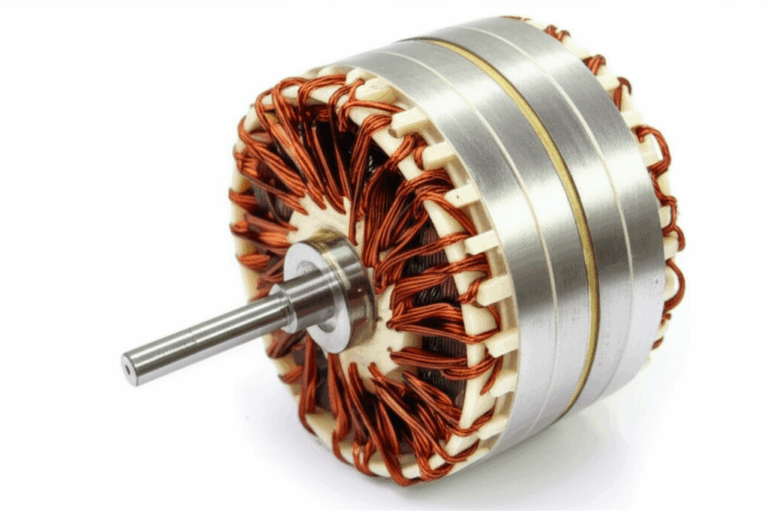
You might be prototyping with an Arduino, an H‑bridge, and a small DC motor. Or you might be building a production BLDC drive for a robot, pump, or e‑bike. Either way, the ceiling on performance starts inside the stack. The quality of the motor core laminations sets losses, temperature rise, acoustic noise, and torque ripple before you even write a line of control code.
This guide uses a simple model. Problem → Explain → Guide → Empower. We start with the engineering problem. We explain the physics in plain language. We guide you through material and process choices. Then we give you practical next steps so you can choose with confidence.
In This Article
- Why Lamination Material Choice Is Critical
- Understanding Core Losses: Eddy Currents and Hysteresis
- A Guide to Common Lamination Materials
- Key Manufacturing and Assembly Processes
- Matching the Right Solution to Your Application
- Control and Prototyping Considerations with Arduino and PWM
- Testing, Quality, and Procurement Checkpoints
- Troubleshooting Performance Issues at the Lamination Level
- Your Engineering Takeaway and Next Steps
Part 1: Why Lamination Material Choice Is Critical
The core’s job is simple on paper. Guide magnetic flux with as little loss as possible. The reality looks messy because modern motors run at higher speeds, higher electrical frequencies, and tighter thermal limits than ever. You push torque density up. You keep cost and mass down. You still need efficiency and quiet operation.
That tension plays out inside the lamination stack. The material sets magnetic permeability, saturation flux density, and core loss. The thickness and coating set eddy current loss. The manufacturing process sets burr height, dimensional tolerance, and stacking factor. Assembly choices set skew, mechanical rigidity, and potential interlaminar shorts. All of that shows up as heat, noise, torque ripple, or reduced service life.
If you control a motor with PWM you modulate voltage fast which raises the harmonic content of the magnetic field. Those harmonics drive extra core loss. The wrong lamination choice forces you to derate. The right choice buys you lower temperature rise at the same torque. It also buys you cost savings because you can reduce copper mass or heatsinking.
Part 2: What’s Really Going On? Core Losses Explained
Let’s demystify the physics without the heavy math. Two loss mechanisms dominate in laminated magnetic cores.
- Eddy current loss: Imagine a river full of tiny whirlpools. A changing magnetic field induces circular currents inside the steel. Those currents waste energy as heat. Thinner, insulated laminations break large whirlpools into many tiny ones which cuts the loss sharply. Eddy current loss scales roughly with the square of lamination thickness and with the square of frequency for a given flux swing.
- Hysteresis loss: Magnetic domains inside the steel flip direction each AC cycle. That flip takes energy because the material resists change. Think of hysteresis as magnetic friction. Materials with lower coercivity, which means less resistance to demagnetization, waste less energy per cycle. The B‑H curve captures this behavior. A slimmer loop means lower loss.
Other contributors matter too.
- Saturation: Push flux density too high and permeability collapses. Torque plateaus. Current spikes. Heat follows. High saturation materials like cobalt‑iron tolerate higher flux but cost more.
- Harmonics and PWM: You rarely drive a core with a pure sine wave. An H‑bridge with PWM injects harmonics into the field. Those harmonics sit at high frequency which bumps eddy current loss. You have knobs to tune like PWM frequency and filtering.
- Temperature: Core loss generally rises with temperature. Coating integrity and interlaminar resistance can degrade at high heat which increases circulating currents between laminations.
- Mechanical factors: Burrs, smeared coatings, or welds that bridge laminations create local shortcuts for eddy currents. That raises loss and sometimes causes hot spots that look random until you cut the stack open.
A few definitions in plain terms help:
- Magnetic permeability: How easily the material lets magnetic field lines pass through it. Think of a sponge that soaks up water. A high permeability material soaks up flux.
- Coercivity: How hard it is to demagnetize the material. Lower coercivity means lower hysteresis loss.
- Stacking factor: The ratio of steel in a stack to the total height. Coating thickness and burrs reduce it. Lower stacking factor means you need more stack height for the same cross‑sectional steel.
- Interlaminar resistance: Electrical insulation between laminations that blocks eddy currents. Coatings and clean processing raise it.
Standards like IEC 60404 define how to measure magnetic properties. ASTM standards such as A677 and A876 specify grades and test methods for non‑oriented and grain‑oriented electrical steels. Lean on them when you compare data sheets because test conditions matter.
Part 3: Your Options Explained
You have two broad sets of decisions. Material selection and manufacturing plus assembly. We will look at both. The goal is not to push a single answer. You will see the trade‑offs so you can match them to your constraints.
Material Considerations
- Non‑oriented silicon electrical steel (NGO or CRNGO)
- Use case: General purpose AC motors, BLDC and PMSM stators, stepper motors. Frequencies from line frequency up into several kHz fundamental with higher harmonics from PWM.
- Thickness: Common gauges include 0.50, 0.35, 0.27, 0.20 mm. Thinner gauges cut eddy current loss at higher frequency. They also cost more and increase handling challenges.
- Pros: Good availability, balanced cost vs performance, isotropic magnetic properties in plane.
- Cons: Higher loss than cobalt‑iron at high frequency. Mechanical strength drops as thickness falls.
- Grain‑oriented silicon steel (GO or CRGO)
- Use case: Transformers and inductors that run with flux aligned to the rolling direction. Rare in rotating machinery because flux rotates.
- Pros: Very low loss along the grain. Great for EI and UI cores where the flux path lines up with the grain.
- Cons: Poor performance off axis. Not a good fit for rotating fields inside stators and rotors.
- Cobalt‑iron alloys
- Use case: High power density motors and generators. Aerospace, turbo blowers, high speed spindles. Electrical frequencies up to tens of kHz.
- Pros: Higher saturation flux density and lower core loss at high frequency. You can push more torque out of a smaller package.
- Cons: High material cost, tougher machining, stricter heat treatment.
- Nickel‑iron and specialty alloys
- Use case: Sensors, actuators, and special machines that demand very low coercivity or specific B‑H behavior.
- Pros: Tunable magnetic properties and soft magnetism.
- Cons: Cost and limited suppliers. Evaluate carefully.
- Amorphous and nanocrystalline ribbons
- Use case: Transformers and inductors for high frequency power electronics. Not typical for slotted stators or rotors because ribbons do not punch into intricate tooth shapes easily.
- Pros: Ultra‑low loss at high frequency.
- Cons: Form factor constraints. Assembly limitations in rotating machines.
- Coatings and insulation classes
- Purpose: Raise interlaminar resistance without hurting stacking factor. Common coat types include inorganic, phosphate, and organic based layers. Backlack coatings activate bonding during cure which turns the stack into a rigid monolith and keeps laminations electrically insulated.
- Trade‑offs: High temperature capability, punchability, weldability, and chemical resistance vary by coating class. Match the coat to your manufacturing steps and varnish bake.
If you want context on the base material, explore what falls under electrical steel laminations. It will help you frame NGO vs GO and where each belongs.
Manufacturing and Assembly Processes
- Progressive die stamping
- Best for: High volume production with stable geometry. Excellent per‑part cost after tooling.
- Pros: Tight repeatability, high throughput, options for interlocking features, knockouts, and burr control.
- Cons: Tooling lead time and cost. Burrs exist and you must control them. Die maintenance matters.
- Laser cutting
- Best for: Prototyping, low volume, and complex shapes that change often. Great for early design iterations when you cannot wait on tooling.
- Pros: Zero tooling cost, fast changeovers, fine features possible. Ideal for pilot runs and for validating electromagnetic designs.
- Cons: Heat affected zone can raise local loss. You must manage cutting parameters and sometimes add post‑processing like stress relief.
- Wire EDM
- Best for: Small volumes that demand pristine edges and tight tolerances. Often used for sample stacks with research grade loss measurement.
- Pros: Very low burr and no thermal damage in the cut path.
- Cons: Slow and costly per part. Not viable for mass production.
- Waterjet
- Best for: Some prototypes where thermal damage from laser would be a concern.
- Pros: No heat affected zone.
- Cons: Taper and edge quality must be managed. Limited practicality for thin gauges.
- Stack assembly
- Interlocking: Tabs and notches in the laminations snap together. Think LEGO bricks that create a rigid core without welding. This avoids interlaminar shorts from welds and keeps magnetic properties intact.
- Bonding: Backlack coated laminations cure under heat and pressure. You get a rigid stack with high interlaminar resistance and low vibration. Great for acoustic noise control and slot harmonic reduction.
- Welding, cleating, and riveting: Mechanical methods that add strength. Use with care because welds bridge laminations and can raise loss. Many teams weld only in low flux regions like the outer yoke of a stator.
- Skewing: Offset the slots across the stack to reduce cogging torque and torque ripple. Step skew and continuous skew both work. Skew complicates stacking and sometimes requires segmented stators.
- Dimensional control and burr management
- Burr height targets often sit below 10 percent of lamination thickness. Lower is better. Burrs cut stacking factor and can smear coatings which causes shorts. Die sharpness and proper clearance matter.
- Stacking factor can fall with rough edges, heavy coatings, or contamination. You need to measure it, not assume it.
If you focus on the stationary side of the machine, explore how stator core lamination choices affect slot fill, winding methods, and acoustic behavior. If you work on the rotating side, take a look at rotor core lamination requirements because mechanical integrity, balance, and magnet retention come to the fore.
Part 4: Which Application Is This For
Tie the choice to the job your motor must do. The right material and stack style depend on speed, voltage, current, control method, and environment.
- General purpose induction or synchronous motors at 50/60 Hz
- Material: NGO silicon steel. M19 or comparable grades for balanced loss and cost.
- Thickness: 0.35 mm or 0.50 mm stands as a solid default. Drop to 0.27 mm if premium efficiency targets demand it.
- Processes: Progressive die stamping with interlocking or welding at the outer yoke. Impregnation varnish to stabilize the stack.
- BLDC and PMSM drives with higher electrical frequency
- Material: NGO steel at 0.20 to 0.27 mm for industrial drives. Consider cobalt‑iron if you push beyond several kHz electrical or you aim for extreme power density.
- Stator: Bonded stacks with skew can cut acoustic noise. Segmented teeth simplify concentrated windings and raise slot fill.
- Rotor: For surface‑mounted magnets use bridges and sleeves to retain magnets mechanically. Core laminations must hold tight tolerances and manage magnet proximity to avoid local saturation.
- If you design BLDC in compact form factors, explore the implications for a bldc stator core because tooth geometry, magnet arc, and lamination thickness set torque ripple and loss.
- Stepper motors like NEMA 17
- Material: NGO steel with moderate thickness, often 0.50 mm. Geometry drives the flux path sharply due to toothed stator and rotor. Precision in tooth profile matters.
- Assembly: Stacks with precise alignment and low runout. Bonding reduces vibration and noise. Magnetic coupling across air gaps magnifies the impact of burrs and concentricity.
- Small servos and micro‑drives
- Material: Thin NGO steel for compact cores. You often see stamped stacks bonded or pressed together in small housings.
- Caveat: Control firmware and PWM choice influence acoustic noise strongly. Thin laminations help, yet mechanical packaging drives many trade‑offs.
- Transformers and inductors
- Material: GO steel in EI and UI stacks when you align the flux with the grain. Amorphous and nanocrystalline when efficiency at high frequency dominates.
- Processes: Stacking and step‑lap techniques reduce joint loss. Different from stator/rotor stacks yet many procurement checks overlap.
- Harsh environments
- Heat: Validate coating class and varnish compatibility for high ambient temperatures. Check loss at elevated temperature during design.
- Vibration: Bonded stacks shine. Interlocking alone can rattle under PWM torque ripple over time.
- Corrosion: Coating and impregnation choices mitigate rust. Stainless fasteners and proper isolation prevent galvanic issues.
Be honest about production scale.
- Prototyping and low volume: Laser cut laminations with bonding give you agility. You can iterate tooth and slot geometry fast. You avoid six‑figure tooling until the design stabilizes.
- High volume: Progressive die stamping lowers piece cost dramatically. You take time to dial in dies so burrs remain low and features run stable across millions of hits.
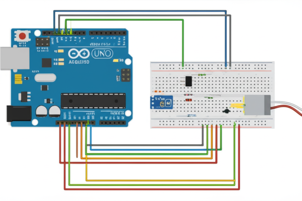
Part 5: Control and Prototyping Considerations with Arduino and PWM
Why include Arduino in a lamination guide. Because most teams prototype with accessible microcontrollers before they spin custom control boards. Control choices influence core loss and thermal behavior which circles back to lamination decisions.
Here is how to think about it.
- PWM frequency and duty cycle
- Low PWM frequencies around 490 Hz or 1 kHz on an Arduino Uno create audible noise. The magnetic core and the stator teeth sing because you inject harmonics into the flux. Higher PWM frequencies reduce audible noise yet can raise eddy current loss. Many designs push PWM beyond 20 kHz to get above human hearing. You balance EMI, switching loss, and core loss.
- If you tune PWM, set realistic expectations during lamination selection. A thinner lamination pays dividends if your drive strategy leans on high frequency PWM.
- H‑bridge and current control
- DC motor control with an H‑bridge driver like L298N or modern DRV8833 gives you direction and speed control. L298N works for simple labs. It burns extra voltage because it uses bipolar transistors. MOSFET based drivers waste less heat.
- Stepper drivers like A4988 and DRV8825 use current regulation and microstepping. Microstepping smooths torque and reduces acoustic noise which lets you judge the core without torque ripple masking it.
- Servo control uses pulse width signals for positional control. A standard SG90 servo takes a PWM style pulse and sets angle. The internal control loop hides lamination behavior under gearing and electronics yet you still see the shape of losses in heat rise.
- External power and grounding
- Motors need more current than microcontroller pins can supply. You use external power and you share common ground with the controller. This prevents reset and brownout issues during switching.
- Flyback diodes across inductive loads protect semiconductors from voltage spikes. Laminations do not change that rule. They change how much mechanical and magnetic energy sloshes around during switching.
- EMI and decoupling
- Switching edges spray noise. Place decoupling capacitors across supply rails and locate them near drivers. Place snubbers where needed. Keep high current loops tight. You protect the controller, the driver, and the measurement chain you use to evaluate lamination choices.
If you work through quick prototypes you will bump into many practical terms. These include arduino motor control, dc motor arduino tutorial, pwm motor control arduino, l298n arduino connection, h-bridge arduino wiring, motor driver for arduino, external power supply arduino motor, arduino uno motor project, arduino motor speed control, arduino dc motor driver circuit, and simple motor control arduino code. You will also see stepper motor arduino setup with a4988 stepper motor driver arduino, drv8825 stepper arduino, nema 17 stepper arduino, unipolar stepper motor arduino with uln2003, and bipolar stepper motor arduino. Servo projects show up as sg90 servo arduino code, servo motor arduino example, continuous rotation servo arduino, and controlling servo with potentiometer arduino.
Troubleshooting overlaps with lamination effects. Motor not spinning arduino sometimes points to wiring. It can also expose core issues if current spikes with no torque. Motor making noise but not moving can be driver, current limit, or poor lamination that saturates early. Arduino resetting or crashing often traces to power supply sag. You also might see motor overheating if lamination loss runs high. If you push speed you learn about motor noise reduction arduino, arduino motor EMI mitigation, proper capacitor across motor arduino placement, and flyback diode motor arduino rules.
For advanced setups you might prototype bldc motor arduino control with sensors. You can try encoder motor arduino and arduino motor speed sensor for feedback. You can explore pid control and even a pid controller library to shape speed and position. You may connect motor with arduino uno through digital pins motor arduino or analog pins motor arduino depending on the driver’s interface. You can test low current motor arduino modules and high current motor arduino solutions with external supplies, voltage regulator arduino motor, mosfet arduino motor driver arrangements, and logic level shifters.
The big takeaway looks simple. Control choices influence harmonic content. Laminations decide how those harmonics turn into heat. You should evaluate both together.
Part 6: Testing, Quality, and Procurement Checkpoints
Engineers and procurement share the same goal. Avoid surprises after release. A short checklist helps.
- Material certificates
- Ask for heat lot traceability and test data for core loss and permeability measured under standard conditions. IEC 60404 tests allow apples to apples comparisons. Confirm thickness, coating class, and mechanical properties.
- Prototype strategy
- Use laser cut laminations for early electromagnetic proof of concept. Expect slightly higher loss than production stampings due to the heat affected zone. If loss matters, specify cut conditions and consider stress relief.
- Add bonded stacks early if acoustic noise and vibration matter. Bonding changes damping. Interlocking alone can rattle at certain PWM frequencies.
- Dimensional and burr control
- Specify burr height limits relative to thickness. Under 10 percent of thickness serves as a starting point. Tighter for high frequency designs with thin lamination gauges.
- Define critical dimensions and geometric tolerances like concentricity of stator bore, circular runout on rotors, slot width, and tooth tip thickness. These influence winding fit and flux density.
- Stacking factor and interlaminar resistance
- Measure stacking factor for your process. Coating choice and edge quality shift real results away from catalog values. Use it in your finite element model so flux density predictions match reality.
- Verify interlaminar resistance after stamping, stacking, and impregnation. Test in multiple regions. Shorts often show up at edges and welded joints.
- Core loss testing at stack level
- Perform ring tests, yoke tests, or back‑to‑back motor tests. Duty cycles and PWM waveforms change losses compared to sinusoidal test rigs. Validate under realistic drive conditions.
- Rotor and stator balance and rigidity
- Check balance on rotors. Bonded laminations distribute load and damp vibration better than loose stacks. Stators benefit from bonding for acoustic performance and structural stability under electromagnetic forces.
- Supply chain and scalability
- Tooling decisions drive unit cost at scale. Estimate break‑even point for progressive die tooling vs laser cut. Include die maintenance and expected volume growth. Set a path for pilot runs that morph into production without a fresh qualification effort.
If your build centers on the stationary magnetic circuit, study options for stator core lamination. If your design risk lives on the rotating side with cages, bridges, or magnet pockets, align specs with rotor core lamination. If you seek an overview of the broader material space, the family of electrical steel laminations frames typical trade‑offs and supply options.
Part 7: Troubleshooting Performance Issues at the Lamination Level
When a test motor overheats at no load or whines at a specific frequency, laminations often sit near the root cause. Work through these patterns.
- Excessive no‑load current and temperature rise
- Likely causes: Too thick a lamination for the operating electrical frequency. Damaged or smeared coatings that short laminations. High burr height. Higher than expected flux density due to stacking factor assumptions.
- Fixes: Move to thinner laminations. Tighten burr control. Switch to a higher temperature and higher dielectric coating class. Update FEA with measured stacking factor.
- Audible noise and tonal components at PWM frequency
- Likely causes: Structural resonances in the stack. Loose interlocking without bonding. Slot harmonics that align with PWM. Non‑skewed tooth geometry.
- Fixes: Increase PWM frequency above audible range or add spread spectrum. Bond the stack. Introduce skew. Change tooth tip geometry and slot opening.
- Saturation in local regions
- Likely causes: Tooth tips too thin. Flux crowding near magnet edges in BLDC rotors. Bridges too narrow. Manufacturing tolerances that cut cross section.
- Fixes: Thicken tips. Add flux barriers or tweak magnet arcs. Adjust bridges. Tighten tolerances on slot and tooth features.
- Rotor heating in magnetized machines
- Likely causes: Eddy currents induced by harmonics in the rotor core and the magnets. Surface mounted magnets without sleeves can add eddy loss. High drive ripple current.
- Fixes: Use thinner rotor laminations. Add sleeves and conductive paths for heat. Clean up current loops through better current control and filtering.
- Stepper motor resonance and missed steps
- Likely causes: Torque ripple interacting with mechanical load resonance. Lamination tooth profile and air gap variations. Driver microstepping not tuned.
- Fixes: Apply microstepping and current shaping via A4988 or DRV8825. Alter tooth geometry and skew. Add damping in mechanical linkages.
- Transformer core hum and heating
- Likely causes: Poor stack pressure or lack of step‑lap. GO steel grain misalignment. Loose laminations that vibrate.
- Fixes: Improve stacking, add step‑lap joints, and increase clamping force. Align the rolling direction correctly for EI or UI cores. Re‑impregnate if needed.
Part 8: Your Engineering Takeaway and Next Steps
Here is the short list you can pin to your wall.
- Pick material for frequency and flux first. NGO steel covers most motors. Go thinner when electrical frequency rises. Use cobalt‑iron when you chase power density.
- Manage eddy current loss with thickness and coating quality. Loss falls as thickness drops. It rises with the square of frequency and with sloppy edges.
- Choose manufacturing for your stage. Laser for prototypes. Stamping for volume. Watch burrs, stacking factor, and interlaminar resistance.
- Bond where noise and structural rigidity matter. Interlocking works. Bonding dampens and seals the deal for acoustic and long‑term stability.
- Model what you measure. Feed real stacking factor and coating behavior into your FEA or lumped models.
- Validate loss under realistic PWM and load. Sinusoidal test rigs paint an incomplete picture. Your drive injects harmonics. Check them.
- Tie lamination decisions to control strategy. Higher PWM frequency may demand thinner laminations. It also may lower audible noise.
If you need a quick orientation to stators and rotors, start with motor core laminations. Then drill into the stationary side with stator core lamination and into the rotating side with rotor core lamination. For a material landscape view, keep electrical steel laminations close at hand. If your project is a compact PMSM or BLDC, the page on bldc stator core will help you think through tooth shape, segmentation, and bonding choices.
Ready for the next step. Outline your application constraints. Electrical frequency, target efficiency, allowable temperature rise, volume projections, and any acoustic limits. Shortlist two material gauges and two stack assembly methods. Ask your lamination partner for sample stacks cut both ways. Test them under your real control waveform. You will walk into procurement and design reviews with data that sets you up for a smoother launch.
—
Appendix for rapid prototyping teams who speak Arduino:
You can use Arduino IDE and boards like Arduino Uno, Nano, Mega, ESP32, or ESP8266 to explore how PWM and control choices affect thermal behavior in cores. Try a motor driver like L298N or DRV8833 for brushed DC. Use A4988 or DRV8825 with a NEMA 17 stepper motor. Test servo motors like SG90 with the Servo.h library. Explore arduino motor direction control with forward reverse motor arduino code and analogWrite for speed control. Log data on motor current draw and arduino motor power calculations while you adjust pwm motor control arduino frequency. Try separate supplies with common ground arduino motor wiring to avoid resets. Add a flyback diode motor arduino circuit around inductors. If the motor not spinning arduino scenario shows up, check wiring diagram dc motor arduino, external power to arduino motor, and motor driver ic arduino pin mapping. For integrated builds, consider an arduino motor shield tutorial or a motor shield v3 arduino stack when you need quick results. You can even test encoder motor arduino feedback and build a simple pid control loop to study how laminations influence efficiency across load points.
Engineers and procurement managers care about the same bottom line. Higher motor efficiency, reduced operational temperature, lower manufacturing cost, and longer service life. You get there when you pair the right lamination material and process with a realistic control strategy and clean manufacturing. That is how you turn stacks of thin steel into reliable motion in the field.