Motor Laminations Made Clear: How Your Choices Drive Efficiency, Cost, and Reliability
Every motor design team hits the same wall. You need higher efficiency and tighter thermal margins, yet costs and timelines keep nipping at your heels. Then the question lands on your desk. Does lamination thickness really matter at my operating frequency? Should I spec a higher grade of non-oriented electrical steel or jump to a cobalt alloy? Will laser cutting wreck my core loss targets, or can I prototype that way and stamp later? If you’ve asked any of those questions, you’re in the right place.
This guide breaks down motor lamination choices in practical engineering terms. We’ll explain why these thin sheets decide so much of your motor’s performance. You’ll see the trade-offs between materials and processes without any smoke and mirrors. Then we’ll arm you with a clear specification checklist, so your next RFQ brings the right parts at the right cost.
In short, we’ll help you go from “I think this is right” to “I know what I’m doing.”
In this Article
- Why Lamination Choices Matter
- Core Loss Fundamentals: Eddy Currents, Hysteresis, and Stress Effects
- Material Selection Guide: NGO Silicon Steel, Cobalt Alloys, and Coatings
- Manufacturing and Assembly Processes: Stamping, Laser, Bonding, and Skew
- Best Fit by Application: Industrial, EV, High-Speed, and Aerospace
- Design and Procurement Checklist
- Cost Drivers and Practical Trade‑offs
- Common Mistakes and How to Avoid Them
- Engineering Takeaway and Next Steps
Why Lamination Choices Matter
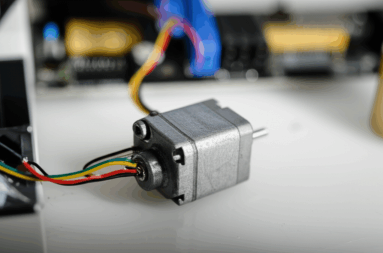
Thin laminations sit at the heart of every efficient electric motor. They don’t look glamorous. Yet they set the ceiling on three critical outcomes.
- Electrical efficiency. Core losses around the stator teeth and back iron turn into heat. Heat eats efficiency and headroom. The right lamination grade and thickness shrink those losses.
- Thermal behavior and power density. Lower loss reduces winding and rotor temperatures. That allows more current for the same thermal envelope or the same power with lower copper loss.
- Cost and manufacturability. Material grade, thickness, and process choice drive die cost, piece price, and lead time. The wrong combo pins you into budget overrun or late program risk.
Here’s the simple idea. Changing magnetic fields inside a motor core create energy losses. Thinner sheets with good insulation block circulating currents. Low coercivity materials switch magnetization with less effort. Clean punch edges and low burr stacks keep performance consistent. Your lamination stack is the house foundation. Get that right and everything above it stands straighter.
If you want a single mental model, use this. Think of eddy currents like tiny whirlpools in a river. Thicker laminations let big whirlpools form. They steal energy and throw off heat. Thinner insulated sheets break those whirlpools into small ripples that fade fast. Less wasted motion. More useful work.
Core Loss Fundamentals: Eddy Currents, Hysteresis, and Stress Effects
Let’s unpack what actually steals energy in an iron core. Engineers often lump it into “core loss” which combines three mechanisms across your operating flux density and frequency.
Eddy current loss
A changing magnetic field induces circulating currents in conductive materials. Those loops flow inside each lamination. They generate I²R loss like any resistor. Eddy loss rises fast with thickness and frequency. Rough rule: eddy current loss scales roughly with the square of lamination thickness and frequency for a given flux density. That is why you see 0.50 mm sheets in 50/60 Hz motors and 0.35 mm or 0.27 mm in high frequency designs.
Analogy time. Drop a paddle in a lazy river and you get a gentle swirl. Toss in a wide board and you churn up a mess. Thick laminations are that wide board.
Hysteresis loss
Magnetic domains flip direction as the field swings. The material wastes energy during each cycle because it resists that flip. That waste shows up as area inside the B‑H loop. Materials with lower coercivity (how hard it resists demagnetization) have lower hysteresis loss. Silicon additions improve electrical resistivity and reduce hysteresis loss compared to plain steel. Cobalt-iron alloys have very high saturation which helps torque density, yet their hysteresis loss can be higher at given frequency unless you choose tailored grades.
Excess loss and manufacturing stress
Real cores don’t behave like textbook curves. You also see “excess loss” tied to domain wall motion and microstructural effects. Cutting adds edge strain and heat-affected zones that increase local losses. Mechanical stress during interlocking, riveting, and welding raises losses too. Bonded stacks can reduce interlaminar vibration which helps audible noise and sometimes loss.
Bottom line. You want a material and a process that hit your required flux density at your electrical frequency with the lowest combined loss under real manufacturing conditions. Lab coupons without burrs or stress will lie to you. Properly manufactured motor core laminations tell the truth in the field.
Material Selection Guide: NGO Silicon Steel, Cobalt Alloys, and Coatings
You have three broad material families in play for most motors. Each brings clear strengths and trade-offs.
Non‑oriented silicon electrical steel (NGO)
This is the workhorse for rotating machines. It comes in many grades and thicknesses like 0.50 mm, 0.35 mm, and 0.27 mm. You’ll see “M” grades in North America (for example, grades like M19 in various thicknesses) and comparable NGO designations elsewhere. Higher grade NGO offers lower core loss at a given flux density and frequency. Thinner material cuts eddy current loss further.
- Pros
- Balanced magnetic properties in all directions which suits rotating flux paths.
- Wide availability and good cost efficiency.
- Mature stamping and coating supply chain.
- Cons
- Core loss rises as frequency climbs into the several hundred Hz range.
- Lower saturation than cobalt-iron which limits peak torque density.
Use NGO for most industrial induction motors, many BLDC machines, appliance drives, and traction motors that operate in the hundreds of Hz electrical frequency range. Pair grade to your flux density and operating frequency rather than habit. Over‑spec costs money. Under‑spec costs efficiency.
Cobalt‑iron alloys (FeCo)
FeCo alloys offer high magnetic saturation (often above 2.3 T) which allows higher torque or power density for a given size. They tend to carry higher hysteresis loss than NGO at the same frequency. Cost runs higher too.
- Pros
- High saturation for aggressive torque and power density targets.
- Useful for high load factors and tight thermal margins.
- Cons
- Expensive material and more demanding processing.
- Higher hysteresis loss at moderate frequencies if you don’t manage flux density carefully.
Use FeCo when you need power in a small package or when you can reduce copper loss by running higher flux without saturating. Aerospace generators, some high-performance traction motors, and compact high-speed machines lean on FeCo when NGO can’t hit the target.
Amorphous and nanocrystalline ribbons
These materials deliver very low core loss at high frequency. You see them in transformers and specialty motors that run at tens of kHz electrical frequency. The price and handling challenges keep them out of most mainstream drives. Ribbon-based cores shape differently and bond differently than stamp‑and‑stack NGO. Consider them for slotless motors or stator back irons at very high frequency if you can harness their strengths.
- Pros
- Very low loss at high frequency.
- Cons
- Costly with limited geometric flexibility.
- Challenging to manufacture into complex tooth geometries.
Insulation coatings and stacking factor
Laminations must be electrically isolated from each other to block eddy currents. Coating classes vary by thickness, thermal endurance, and punchability. Standards like ASTM A976 define coating classes and test methods. Choose coatings for your curing temperatures, bonding method, and dielectric needs.
- Thin, hard coatings punch well and support tight burr control.
- Self-bonding coatings activate under heat and pressure during stacking. They create strong, low-noise stacks without welds or rivets.
- Thicker coatings lower stacking factor which increases stack thickness for the same number of sheets. That changes flux path length and slot geometry.
Good practice. Call out the coating class, minimum dielectric strength, and compatibility with your bonding or welding process. Keep your stacking factor target clear in drawings, since it directly impacts the effective back iron and tooth dimensions.
If you want a quick refresher on material options and how they’re processed, skim this page on electrical steel laminations.
Manufacturing and Assembly Processes: Stamping, Laser, Bonding, and Skew
You’ll rarely get the material choice wrong if you ask good questions. You’ll hurt performance fast if you pick the wrong manufacturing process for your phase of development or your volume. Let’s break down the main options.
Stamping with progressive dies
Stamping wins for medium and high volume. Progressive dies deliver consistent geometry, high throughput, and low per‑part cost after the tool amortizes.
- Pros
- Best cost at volume.
- Tight tolerances and repeatable burr control if the die stays sharp.
- Supports interlock features and segmental stator designs.
- Cons
- Tooling cost and lead time.
- Die wear increases burr height and stress unless you maintain it well.
Target low burr height and deburr processes in your spec. Burrs alter airgap effective length and increase interlaminar shorting risk. Control radial stack growth and skew phase alignment in production to protect torque ripple and acoustic targets.
Laser cutting
Laser cutting shines in prototyping and low volume. It handles complex geometries and fast design turns. Heat-affected zones raise local losses and can reduce permeability near edges. You can mitigate some of that with process optimization. It still trails stamping in loss performance for production stacks.
- Pros
- Fast iteration and low upfront cost.
- Complex profiles and small feature changes without new tools.
- Cons
- Edge thermal damage increases core loss.
- Slower per part and more expensive at volume.
Use laser to de‑risk the design. Stamp when you commit to volume. If you must use laser beyond prototyping, qualify the loss delta with actual ring core or stator segment tests at your operating frequency.
Wire EDM and waterjet
Both avoid significant heat input at the cut edge. EDM yields very clean geometry with minimal mechanical stress. It moves too slowly for volume. Waterjet avoids heat but can cause edge roughness and burr that you must manage. You will use these sparingly for special shapes or fixtures.
Stack assembly: interlocking, welding, riveting, and bonding
How you build the stack matters as much as how you cut laminations.
- Interlocking
- Tabs and lances in the lamination bite each other. It works like LEGO bricks. You get mechanical strength with minimal added parts.
- Pros: Low cost and fast. No additional materials.
- Cons: Local stresses increase loss. Tabs reduce effective area slightly. Not ideal for very thin gauges.
- Welding and cleating
- Spot welds or external cleats hold stacks. Good for rotors or large stators that need robust integrity.
- Pros: Strong and simple.
- Cons: Heat and stress near welds degrade local magnetic properties. You need careful weld placement to avoid flux hotspots.
- Bonding and backlack
- Adhesives or self-bonding coatings cure under heat and pressure during stacking. They create rigid stacks with low vibration and very low interlaminar shorts.
- Pros: Great magnetic performance and acoustic behavior. No weld heat damage. Smooth OD for tight fit assemblies.
- Cons: Added process control and cure cycles. Coating compatibility must be correct. Cleanliness matters.
Choose the assembly method with your performance targets in mind. If you chase every last watt of loss reduction, bonded stacks often win. If you chase cost at scale with robust mechanical performance, interlocks or welds may fit better.
Skew, segmentation, and rotor choices
- Skew
- Skewing stator teeth or rotor slots reduces cogging torque and torque ripple. It spreads slot harmonics across electrical angle. It can reduce back EMF ripple. You pay a small hit in peak torque and winding complexity. Specify skew angle and step size clearly, and align it with your pole and slot count.
- Segmental stators
- Segmental tooth modules ease winding insertion in dense slot designs. They reduce active slot fill friction and allow higher fill factor. They also change stack stress distribution and introduce more joints. You must plan bonding, interlock, or weld strategies for segments.
- Rotor laminations
- Induction rotors use solid stacks with bars and end rings. PM rotors use buried or surface magnets with retention sleeves or bridges. Assembly methods change by rotor type. Insist on controlled burrs and balance for smooth operation. If you need a primer, this overview of rotor core lamination is a quick read.
For stator design specifics and how those stacks impact performance, see stator core lamination.
Best Fit by Application: Industrial, EV, High‑Speed, and Aerospace
You don’t pick a material or process in a vacuum. Fit the solution to your motor topology, frequency, and power density aim.
Industrial 50/60 Hz induction motors
- Profile
- Low to moderate electrical frequency. Robust duty cycles. Focus on efficiency, cost, and reliability.
- Recommendations
- NGO silicon steel in 0.50 mm or 0.35 mm thickness. Pick grade for target efficiency class.
- Stamping with progressive dies. Interlock or weld stacks as needed.
- Emphasize burr control, coating class, and stacking factor in your prints.
- Notes
- Improve IE3 to IE4 performance by stepping down thickness and selecting low‑loss NGO grades. Weigh ROI versus copper and mechanical cost.
BLDC and interior permanent magnet (IPM) motors for appliances and light traction
- Profile
- Electrical frequency often 200–600 Hz depending on pole count and speed. Tight acoustic and efficiency targets. Cost still matters.
- Recommendations
- NGO in 0.35 mm or 0.27 mm thickness with low loss at your B and f point. Consider bonding for noise reduction and lower interlaminar shorts.
- Stamping for production. Laser for early development with a plan to qualify stamped loss delta.
- Notes
- Use skew or fractional slot windings to tame cogging and torque ripple. Confirm that skew strategy plays well with your magnet and slot geometry.
EV traction motors and high‑power industrial drives
- Profile
- High power density, rising electrical frequencies, and wide speed range. Thermal headroom is gold.
- Recommendations
- Start with premium NGO at 0.27 mm or thinner. If you need more flux and compactness, evaluate FeCo at similar thickness.
- Bonded stator stacks are attractive for NVH and loss control. Invest in tight burr limits and consistent coating application.
- Notes
- Confirm your loss model with measured coupons or stacks at representative flux and frequency. Include the effect of magnet slotting and bridge saturation in your FEA and your tests.
High‑speed compressors, aerospace actuators, and specialty machines
- Profile
- Electrical frequencies in the kHz range. Extreme power density or compact footprints. Precision assembly.
- Recommendations
- Evaluate FeCo for saturation and amorphous or nanocrystalline for extreme frequency zones where geometry allows. Use very thin gauges and bonded stacks.
- Wire EDM or fine laser can serve early prototypes. Transition to precision dies if volume warrants it and if performance holds after stamping.
- Notes
- Balance and runout control on rotors grow critical as speed rises. Specify tight limits and test on instrumented rigs.
Transformers vs motors
Designers sometimes ask if grain‑oriented (GO) steels can help motors because GO boasts very low core loss along the rolling direction. GO loves a fixed flux direction which suits transformers. Rotating machines swing flux across many angles. That’s why motors use non‑oriented (NGO) grades. Save GO for magnetic circuits where flux stays aligned.
Design and Procurement Checklist
Use this checklist to align your team, your supplier, and your test lab. It doubles as a solid RFQ template.
- Material
- Grade and thickness. For example, NGO 0.35 mm low‑loss grade per mill spec with mill certificate. Or FeCo grade with target saturation and loss.
- Core loss targets at your operating induction and frequency. Specify test conditions. Don’t quote catalog values at 1.5 T and 50 Hz if you run 1.2 T and 400 Hz.
- B‑H curve requirement if you simulate with nonlinear models. Request mill curves or measured single sheet data at room temperature.
- Insulation coating class per ASTM A976. Note dielectric strength minimum and cure compatibility if bonding.
- Stacking factor requirement and method of verification.
- Geometry and tolerances
- Critical dimensions with GD&T for circularity, concentricity, and flatness. Call out the airgap critical features with tighter limits.
- Burr height limits and deburr method. Set different burr limits for tooth tips and back iron if needed.
- Skew angle and step size. Alignment features between segments. Magnet pocket tolerances and bridge thickness for PM rotors.
- Slot wedge and slot liner geometry if relevant. Winding insertion clearances.
- Manufacturing method
- Cutting method for prototype and for production. Note that loss acceptance uses production‑representative parts unless otherwise stated.
- Stack assembly method. Interlock, weld, rivet, or bond. State any weld keep‑out zones near high flux regions.
- Cure profile for bonding. Coating type for backlack and temperature limits.
- Post‑processing like stress relief if permissible for the coating and material. Many NGO grades come fully processed and do not require anneal. If you consider anneal, verify coating stability and magnetic property changes with your supplier.
- Quality and verification
- Material certifications. Request compliance with relevant standards like ASTM A677 or A683 for NGO, and coating specifications per ASTM A976. Use the IEC 60404 series for magnetic testing methods.
- Test method for core loss measurement. Epstein frame, single sheet tester, or ring core. State flux waveform and frequency.
- PPAP or similar production part approval if you need automotive‑grade quality.
- Traceability at coil, lot, and stack level. Labeling requirements and packaging to protect coating and edges.
- Logistics and planning
- Tooling ownership and maintenance plan for dies and fixtures. Expected die life and burr growth monitoring.
- Delivery formats. Stacks, loose laminations, or bonded cores. Surface protection in transit.
- Prototype path to production. Plan for a measured delta between laser cut prototypes and stamped production cores.
Well written specs turn into good parts. Vague specs produce debates and delays. Engineers don’t have time for either.
Cost Drivers and Practical Trade‑offs
You can dial cost and performance like a two‑knob radio. Turn one and you bump the other. Here’s what moves the needle.
- Thickness and grade
- Thinner gauges cost more per kilogram and increase part count per stack. They cut eddy current loss which can improve overall system efficiency and lower copper cost. Balance these effects with real motor simulation and test.
- Dies and piece price
- Progressive dies demand upfront investment and lead time. They pay off fast for volume builds. Laser and EDM dodge the tool yet carry higher per‑piece cost.
- Yield and nesting
- Part geometry and lamination size dictate how many pieces you pull from a sheet or coil. Smart nesting improves yield and cuts cost. Tight punch‑to‑die clearance controls burr yet affects tool wear and yield.
- Coatings and bonding
- Self‑bonding coatings and adhesive bonding add process steps and cure cycles. They improve NVH and reduce magnetic losses near welds. They can cut assembly labor and secondary operations. Price the full stack, not just the lamination itself.
The golden rule. Don’t chase lamination cost in isolation. A thinner, better grade can reduce winding copper, insulation complexity, and heatsink size. That saves more than it costs. Model the whole motor and verify with A/B builds.
Common Mistakes and How to Avoid Them
I’ve seen the same five missteps repeat across programs. You can sidestep them with a short checklist.
- Using grain‑oriented steel for rotating machines
- It looks tempting on paper because GO loss is low in one direction. Motors don’t run flux that way. Use non‑oriented grades.
- Quoting catalog core loss that doesn’t match your B and f
- Loss curves move fast with frequency and induction. Test and specify at your operating point.
- Ignoring the effect of cutting on magnetic properties
- Laser and dull dies add stress and heat‑affected zones. The lab coupon won’t show that. Test stacked and cut parts not just raw sheet properties.
- Over‑welding stacks
- Welds land heat right where flux flows. Limit weld size and place them in low‑flux regions. Prefer bonding when loss and NVH targets run tight.
- Under‑specifying burr control
- Burr height and direction matter in tight airgaps. High burrs increase local saturation and friction during winding. Specify limits and inspect them.
One more subtle pitfall. Designers sometimes assume a one‑size grade works everywhere. It rarely does. High‑speed auxiliaries want different laminations than the main traction motor. Right tool for the job.
Case Snapshots: How Small Choices Changed Big Outcomes
- Appliance BLDC fan
- Problem: The design missed efficiency by 2 points at 400 Hz electrical frequency. Laser‑cut prototypes looked fine in FEA yet ran hot in test.
- Change: Switched to 0.35 mm NGO with a lower loss grade and bonded stacks. Stamped tools replaced laser. Spec included burr limits and coating class compatible with bonding.
- Outcome: Core loss dropped by double digits in percent. Motor hit efficiency target with 5% less copper. NVH improved at blade pass frequencies.
- Compact aerospace generator
- Problem: Power density target forced near‑saturation flux levels in the stator teeth. NGO saturated too early which drove copper loss up to keep torque.
- Change: Moved to FeCo at 0.20 mm thickness in critical teeth with bonded stacks. Validated heat rise and balance at speed with instrumented tests.
- Outcome: Size and weight targets held without thermal overruns. Cost increased at lamination level yet dropped at system level with smaller housing and reduced cooling mass.
- Industrial pump motor upgrade
- Problem: Needed IE4 efficiency without exploding BOM cost.
- Change: Stepped down thickness from 0.50 mm to 0.35 mm NGO with a modest grade improvement. Tightened burr control and skewed stator by one slot to cut noise. Kept interlocks to hold cost.
- Outcome: Cleared IE4 with a manageable price premium. Warranty returns dropped due to lower heat loading in the stator end turns.
These are typical moves. You can borrow the pattern for your own design.
Where Stator and Rotor Choices Meet in Practice
You will often optimize stators and rotors differently. Stators see concentrated winding heat and drive acoustic behavior. Rotors in PM machines carry magnets which change flux paths and slot harmonics. Induction rotors face bar current and end ring heating.
- Stators
- Favor bonding when NVH and loss targets bite hard. Control tooth tip burrs and wedge fit. Plan winding insertion with slot liners and corner relief.
- If you’re unsure how stator stack choices ripple through performance, this overview on stator core lamination provides a solid base.
- Rotors
- Keep magnet pockets and bridge thickness within tight tolerances. Balance becomes critical at speed. Place welds away from peak flux regions.
- For a quick primer on rotor geometries and stack choices, scan rotor core lamination.
Most teams find it helpful to review both lamination halves together. That cross‑check catches stack height mismatches, magnet retention assumptions, and skew alignment issues before you order tools.
Standards and Testing: Keep It Real and Reproducible
Trust grows when you measure with the right yardstick. You don’t need to become a materials lab. You do need to cite the right frameworks.
- Reference the IEC 60404 series for magnetic materials testing. It covers methods like Epstein frame and single sheet tests.
- Use ASTM A677 or A683 for electrical steel specifications where applicable. Use ASTM A976 for insulation coating classification and tests.
- Call out flux waveform during tests. Sine versus PWM excitation changes loss. State frequency, induction level, and test temperature.
- Agree on sample geometry and cutting method for test coupons. A laser‑cut ring does not equal a stamped tooth tooth in loss behavior. Use production‑representative parts for final acceptance.
If you set expectations in writing, you reduce emails and rework. More importantly, you get cores that perform like your models.
Your Shortlist for BLDC and PM Projects
BLDC stators and IPM rotors dominate many new programs. Two quick tips will save time.
- Use NGO 0.35 mm or 0.27 mm for most BLDCs that run a few hundred Hz with moderate flux. Move to thinner gauges or FeCo when you hit either very high speed or sharp power density targets.
- Validate laser‑to‑stamp deltas early. Build a small stamped pilot stack. Measure back‑to‑back with a laser stack at the same B and f. Bake that delta into your early thermal models.
If you need a refresher on BLDC core options and how stacks come together, this short page on motor core laminations lays out the essentials without fluff.
Design and Business Guidance in One Page
Here’s a practical way to make the next step low risk and high value. Treat your lamination decision as a three‑gate review.
- Gate 1: Define operating window
- Electrical frequency range and duty cycle. Peak and RMS flux density targets. Thermal limits and NVH constraints. Put real numbers on the table.
- Gate 2: Choose material and process candidates
- Shortlist two NGO grades and one stretch option like FeCo or thinner NGO. Pair each with a process plan. Laser for early samples then stamping with bonding or interlock for production.
- Gate 3: Build and measure representative stacks
- Test core loss at your B and f. Verify burr and stacking factor. Install in a mule motor to capture NVH and back‑EMF shape. Update models with real data. Pick the winner.
This approach aligns engineering, purchasing, and operations early. It cuts risk. It saves cost downstream.
Engineering Takeaway and Next Steps
Let’s wrap it up with the essentials.
- Core loss has three culprits. Eddy currents, hysteresis, and excess loss due to stress. Thickness, grade, and process decide how big each culprit gets.
- NGO silicon steel covers most motor needs. Pick thickness and grade for your actual flux and frequency. Move to FeCo when saturation headroom drives power density.
- Manufacturing matters as much as material. Stamp for production. Laser for prototypes with eyes wide open about loss penalties. Bond stacks when NVH and loss targets tighten.
- Match the solution to the application. Industrial 50/60 Hz motors want robust NGO at 0.50 or 0.35 mm. EV and high‑speed systems often need 0.27 mm NGO or FeCo with bonded stacks.
- Specify clearly. Material grade, thickness, coating class, core loss targets at your B and f, stacking factor, burr limits, and assembly method. Reference IEC 60404 and ASTM standards.
Action you can take today
- Build a one‑page lamination spec that includes frequency, flux density, and core loss targets under test conditions. Share it with your supplier before you ask for quotes.
- Plan a stamped pilot even if you start with laser. Measure the real delta in core loss and NVH.
- If you need quick guidance on stator stacks, rotors, or material options, review these primers on stator core lamination, rotor core lamination, and electrical steel laminations. They take minutes to scan and help teams get aligned fast.
Good laminations don’t just make motors run cooler. They make programs run smoother. Choose wisely. Test honestly. Then ship with confidence.