Motor Laminations Made Clear: How to Choose Thickness, Material, and Processes for Better Motors
Every design engineer runs into this question sooner or later. How do lamination material and thickness affect motor efficiency, heat, and cost? It’s a deceptively simple line item that drives performance, manufacturability, and lifetime economics. If you’re weighing tradeoffs for a new motor or refreshing a legacy design you’re in the right place.
You want clear rules of thumb without hand waving. You also need enough physics to defend your choices with your team and your supplier. Let’s walk the problem, explain what drives losses and torque, compare practical options, and close with a checklist you can use this week.
In this guide I’ll use the “Problem – Explain – Guide – Empower” flow so you can move from uncertainty to a defensible spec and a clean RFQ.
In This Article
- Why Lamination Choice Is Critical
- The Fundamentals: Core Losses, Flux, and Frequency
- Your Options Explained: Materials for Laminations
- Your Options Explained: Manufacturing and Assembly Processes
- Which Solution Fits Your Application
- Data, Standards, and What to Ask Suppliers
- Your Engineering Takeaway and Next Steps
Part 1: Why Lamination Choice Is Critical
Two forces tug at your design. You want high efficiency and power density. You also want predictable cost, stable lead times, and a process that scales. Lamination decisions sit at this intersection.
Here’s the core problem:
- Thinner laminations reduce eddy current losses at higher frequencies but they raise stamping cost and may complicate stacking and bonding.
- Higher grade electrical steels cut hysteresis loss and push peak flux density up but they cost more and may have longer lead times.
- Manufacturing stress from cutting and welding can bump losses by double digits if you ignore stress relief or edge quality.
Small choices compound. A 1–2 W/kg reduction in core loss can drop winding temperature rise, which lets you use a lower slot fill or a smaller fan. That can shave BOM cost and improve acoustic noise. On the flip side a half step down in steel grade might save on material but cost you more in copper or thermal management. The scoreboard sits in the system, not in one line item.
Your goal is not “the best lamination.” Your goal is “the right lamination for this electromagnetic and production envelope.”
Part 2: What’s Really Going On? The Engineering Fundamentals
Let’s unpack the physics in plain English.
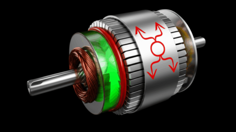
Magnetic materials in motors face alternating magnetic fields. They waste energy in two main ways:
- Hysteresis loss: Energy you spend every cycle to flip the magnetic domains. Think of pushing a heavy door open and closed. Some energy never comes back as useful work. It turns into heat. Hysteresis scales roughly with frequency and the area of the B-H loop. Materials with lower coercivity have smaller loops and lower loss.
- Eddy current loss: Those are the “whirlpools” of current that form in the steel when the magnetic field changes. They circulate in the plane of the lamination and create I²R heating. Eddy current loss scales with the square of both thickness and frequency.
A helpful picture
- Imagine a wide river in flood. Large whirlpools form and churn. That’s a thick lamination at high frequency. Now place rocks across the flow to break the water into smaller channels. Each whirlpool shrinks. That’s what thin, insulated laminations do inside the motor core.
Key terms without jargon overload
- Magnetic permeability: How easily magnetic flux flows through a material. Picture a sponge soaking up water.
- Saturation flux density (Bsat): The ceiling for how much flux the material can carry before it “stops being helpful.” Hit the ceiling and torque drops or current soars.
- Coercivity: How hard it is to demagnetize the material. Lower coercivity means less hysteresis loss per cycle.
- Stacking factor: The fraction of a stacked core that is actual steel vs insulation and air. Higher stacking factor means more effective steel in a given stack height.
Frequency and waveform matter
- Classic induction motors run on 50/60 Hz. Many EV traction and aerospace motors run much higher electrical frequencies. BLDC and PMSM drives add PWM switching harmonics on top of fundamental frequency. Loss rises with frequency, and PWM harmonics add to that. Thin gauge and low-loss grades shine as frequency climbs.
Flux density matters too
- Loss rises fast with flux density. Many loss catalogs provide W/kg at multiple B and f points. Designers sometimes overfocus on loss at one test point. Don’t do that. Look across the expected operating map. Include PWM spectral content if your inverter switching frequency and dead time push meaningful ripple into the core.
Why insulation between laminations matters
- Interlaminar insulation isolates each sheet electrically. That breaks eddy current paths. Coating type affects interlaminar resistivity, punchability, weldability, and bonding. It also impacts stacking factor. Choose it with the process in mind, not after.
Where losses show up in the machine
- Stator teeth and back iron carry high flux swing. Rotor laminations can see significant loss in permanent magnet machines because of slotting harmonics and high electrical frequency. Skew and tooth geometry can cut torque ripple but they change local flux patterns and can shift losses around the core.
Bottom line
- Eddy current loss hates thickness and loves frequency. Hysteresis hates high coercivity and loves frequency. Both hate high flux density. You can manage each lever with material and process.
Part 3: Your Options Explained — Materials for Laminations
The industry has a deep bench of electrical steels and specialty alloys. You don’t need to know every catalog. You do need to know how to navigate the trade space.
Start with the big split
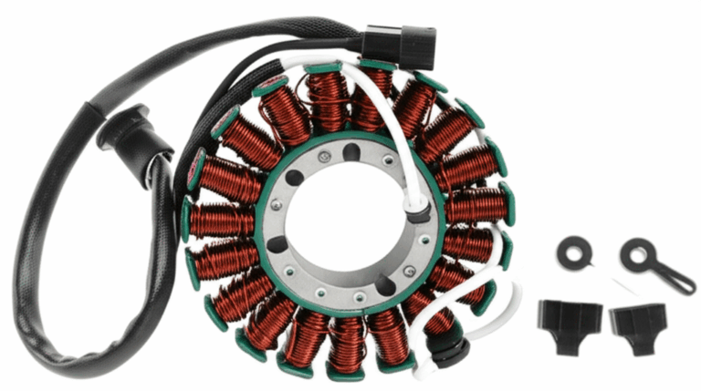
- Non-oriented electrical steel (NOES): The workhorse for rotating machines because its magnetic properties are similar in all directions. Often listed as M-grades in North America or as specific grade codes per EN/IEC standards. You’ll see common thicknesses like 0.50 mm, 0.35 mm, 0.27 mm, and down to 0.20 mm or thinner for higher frequency machines.
- Grain-oriented electrical steel (GOES): Optimized for one direction of magnetic flux. That makes it ideal for transformers and inductors, not rotating machines. It can saturate efficiently along the rolling direction but loses the advantage when flux rotates.
Silicon steel families
- Silicon alloying lowers core loss and boosts resistivity. More silicon usually improves loss yet reduces mechanical toughness. Very thin gauges can be more brittle. Pay attention to punchability and burr height in your process.
- Use loss data at relevant flux densities and frequencies. Avoid comparing apples to oranges. If a data sheet lists W/kg at 1.5 T and 50 Hz and your design sees 1.2 T at 400 Hz adjust your mental model.
Cobalt-iron alloys
- Cobalt-iron alloys offer higher saturation flux density than silicon steels. This helps if your design craves high power density and you can accept higher material cost. They often need thin gauges to control loss at frequency. Many aerospace and turbo machinery designs lean this way.
Nickel-iron alloys
- Certain Ni-Fe grades offer very low coercivity and high permeability at low to moderate flux density. They can cut hysteresis loss but may have lower Bsat. You often see them in specialty sensors, not mainstream traction motors.
Thickness: the blunt instrument with a bite
- Thinner is better for eddy current loss because eddy loss scales with thickness squared. Going from 0.35 mm to 0.20 mm can cut eddy loss by roughly a factor of three at the same frequency and flux. It raises cost and can complicate stamping and handling. Very thin laminations may justify laser cutting for prototyping or short runs.
- Balance thickness against slot geometry. Teeth with narrow tips at thin gauge can become fragile during stacking or interlocking. Confirm stack integrity early with your supplier.
Coatings and insulation classes
- Inorganic coatings bring high resistivity and thermal stability. Organic coatings can aid bonding and reduce noise but may limit weldability. Hybrid coatings bridge the gap.
- Ask about coating class, typical interlaminar resistance, and compatibility with your assembly method. Backlack and other bonding varnishes can provide strong stack integrity without welding, which avoids heat-affected zones.
Saturation and torque margins
- High Bsat lets you design smaller back iron or push more torque in short bursts. Watch loss at your continuous operating points. What helps in peak conditions can hurt in steady cruise if your loss map shifts.
Supply reality
- Grade availability varies by region and market cycle. Some premium thin gauges face longer lead times. Lock early with procurement and keep alternates vetted to de-risk supply.
Where to go deeper next
- If you’re comparing across material families see supplier loss maps that show W/kg vs B and f. Work with a consistent test standard so comparisons hold water. IEC 60404 series covers magnetic properties and test methods. ASTM standards address electrical steel sheet types and coatings.
To explore the material landscape and component types, this primer on electrical steel laminations gives a clear overview of grades and applications.
Part 4: Your Options Explained — Manufacturing and Assembly Processes
Material choice is half the story. How you cut, stack, and join laminations can make or break performance.
Cutting methods
- Progressive die stamping: The gold standard for high volume. Low cost per part once you amortize the tooling. It offers tight repeatability. It introduces plastic deformation near edges which raises local loss. Control burr height, die wear, and strip lubrication. Consider stress relief anneal for tight loss budgets.
- Laser cutting: Great for prototypes and low volume with complex geometries. No tooling cost. Heat-affected zones can raise loss and embrittle edges if parameters are off. Choose laser parameters and coatings with care. Post-cut anneal can recover properties.
- Wire EDM: Precise with minimal thermal damage. Slow and costly for volume. Useful for critical prototypes or very hard alloys.
- Waterjet: Avoids heat but can struggle with edge quality and taper. Rare in production cores.
Stacking and joining
- Interlocking: Tabs formed during stamping lock laminations like LEGO bricks. This gives fast assembly and avoids weld heat but adds local stress. Good for many industrial motors.
- Welding: Spot or seam welds deliver strong stacks. Heat can degrade local magnetic properties and raise loss. Use controlled schedules and keep weld zones away from high flux areas.
- Bonding varnish (backlack and similar): Adhesive-coated laminations cure under heat and pressure to create rigid stacks with excellent vibration damping and no weld heat. Great for acoustic performance and thin laminations. Requires process control and clean handling.
- Rivets or pins: Simple and proven. They introduce holes and local stress. Use sparingly and away from peak flux paths.
Annealing and stress relief
- Cutting induces residual stress. Stress increases hysteresis loss. A proper stress relief anneal can claw back performance. Follow material supplier guidance on temperature windows and atmospheres. Some coatings survive anneal, some do not.
Burrs and edge quality
- Burr height drives interlaminar shorting which raises eddy currents. It also lowers stacking factor. High frequency machines are sensitive to burrs. Specify burr height limits at critical edges. Inspect early in a PPAP or first article run.
Skew and slot details
- Skew reduces cogging torque and torque ripple. It slightly increases end-turn copper length and may raise iron loss. The net often favors skew in BLDC and PMSM designs for NVH and smoothness. Align skew strategy with your rotor and stator lamination suppliers. Tolerances matter.
- Tooth-tip geometry and fillet radii influence both flux crowding and punch life. Small fillets can look great in FEA and punish you in the toolroom.
Tolerances and flatness
- Flat laminations stack well and keep air gaps consistent. Tight ID/OD roundness supports rotor dynamics. Work with GD&T that reflects how the stack locates in the final assembly. Don’t chase microns you don’t need.
Cleanliness and insulation integrity
- Oil, debris, and handling damage can compromise coating resistivity. That raises loss and noise. Audit line cleanliness and storage conditions. Consider lot-level interlaminar resistance checks.
Where a process-heavy explainer helps, this page on motor core laminations walks through how core stacks come together in production.
Part 5: Which Solution Fits Your Application
Let’s map common applications to practical choices. Use these as starting points not as commandments.
Industrial induction motors at 50/60 Hz
- Material: Mid-grade NOES, thickness 0.50 mm or 0.35 mm depending on efficiency target and frame size.
- Process: Progressive die stamping with interlocking or welding. Stress relief only if loss targets demand it.
- Notes: Focus on burr control, stacking factor, and airflow for thermal headroom.
High-speed BLDC/PMSM for fans, pumps, and robotics
- Material: Low-loss NOES in 0.35 mm down to 0.20 mm. Consider premium thin gauges for electrical frequencies above a few hundred hertz. For very high speed, examine cobalt-iron for rotor or stator if budget allows.
- Process: Stamping for volume. Laser cutting for prototypes and quick design iterations. Bonding varnish for thin laminations to keep stacks quiet and rigid.
- Notes: Include PWM harmonic content in your loss model. Skew to tame cogging and acoustic noise.
EV traction and hybrid drives
- Material: High-grade NOES or cobalt-iron depending on power density and efficiency class. Gauges from 0.27 mm to 0.20 mm are common. Watch supply and cost swings.
- Process: Precision stamping with tight burr limits and robust die maintenance. Bonded stacks for noise and rigidity. Stress relief and magnet insertion processes need tight control.
- Notes: NVH targets and thermal budgets drive choice. Losses at partial load with high inverter switching frequency can dominate. Validate across the drive cycle, not just at peak.
Aerospace and turbo machinery
- Material: Cobalt-iron thin gauge for high Bsat and high frequency. Expect tight quality controls and certifications.
- Process: Laser or fine-blanking for prototypes, then high-precision stamping. Bonding preferred to avoid weld-affected zones.
- Notes: Weight and temperature margins rule the day. Budget follows performance.
Small fractional horsepower motors and appliances
- Material: Cost-optimized NOES at 0.50 mm or 0.35 mm. Use standard grades with solid availability.
- Process: Stamping and interlocking. Minimal post-processing.
- Notes: Focus on reliable supply and die life. Noise expectations vary by product.
Transformers and inductors
- Material: GOES for core legs aligned with the rolling direction. Target low losses at 50/60 Hz or at your specific switching frequency if you’re in power electronics.
- Process: Shearing or step-lap assembly. Anneal and coating choices matter.
- Notes: Different playground than rotating machines, and worth calling out separately.
If your project involves a BLDC topology, this overview of a BLDC stator core can help you align slot shapes, skew, and bonding with your target torque ripple and efficiency.
Part 6: Practical Design Guidance and Rules of Thumb
You want a path from theory to decisions. Use these guidelines to get there fast.
Set your operating map first
- Identify continuous and peak operating points. Capture fundamental electrical frequency and expected inverter switching frequency. Estimate PWM harmonics that matter.
- Define maximum flux densities in teeth and back iron from FEA. Let’s say 1.2–1.6 T in typical NOES designs. Keep margin away from deep saturation to protect efficiency and thermal headroom.
Pick thickness with frequency and cost in mind
- At 50/60 Hz most designs run 0.35–0.50 mm. At 200–400 Hz many designs step down to 0.27–0.20 mm. At higher frequencies you often need 0.20 mm or thinner.
- Check the manufacturing impact. Thinner gauges require tighter die control and can add scrap sensitivity. Run the math on total cost of ownership, not just material price per kilogram.
Choose material grade for loss and Bsat
- If you target higher flux density for torque density you may push toward premium NOES or cobalt-iron. If your loss budget is strict at moderate B you may choose a low-loss NOES without cranking Bsat.
- Validate with supplier loss curves that match your B and frequency map. Ask for stamped-and-annealed data if available because processing changes the picture.
Decide coating and stack method together
- Interlocking needs coatings that tolerate forming. Welding wants coatings that don’t interfere with weld quality. Bonding varnish needs clean surfaces and defined cure profiles.
- Insulation thickness lowers stacking factor. Account for it in slot fill and back iron thickness.
Manage stress and edge effects
- If your design lives or dies by a few W/kg, include stress relief in your plan. This is common in premium EV and aerospace designs.
- Specify burr height limits at critical edges and measure them. A sharp edge is not just a cut hazard, it can be a loss hazard.
Model with reality checks
- Include lamination stacking factor, slotting harmonics, and skew in electromagnetic FEA. Couple the core loss model with thermal analysis so you see how iron loss affects winding temperature and demagnetization risk.
- Validate model assumptions with small-sample spin tests on prototype stacks. High-frequency calorimetry and Epstein-frame measurements help if available.
Don’t forget rotor losses in PM machines
- Modern PMSMs can push significant iron loss into the rotor. Slot opening, stator tooth harmonics, and PWM ripple all contribute. Rotor skew and magnet barrier design help. Rotor lamination grade and thickness matter too.
For stator specifics and how stack choices play out in the yoke and teeth, this page on stator core lamination offers a focused look. For rotor-specific tradeoffs in PM and induction designs, see rotor core lamination.
Part 7: Common Pitfalls and How to Avoid Them
- Comparing loss data at the wrong points: You review W/kg at 1.5 T and 50 Hz while your motor lives at 1.1 T and 400 Hz. The ranking flips. Always compare at relevant B and f.
- Ignoring processing effects: Laser-cut prototypes look great in FEA yet run hot. Heat-affected edges and no anneal make loss jump. Align prototype process with production or adjust with measured correction factors.
- Overlooking insulation and stacking factor: You design to a perfect steel fraction that reality never hits. Coating thickness, glue lines, and trapped air drop stacking factor by several percent. That matters for inductance and flux density.
- Pushing thin laminations without a handling plan: 0.20 mm parts need gentler forming, smarter interlocking, and sometimes bonding. Bake these constraints into the DFM conversation early.
- Treating stator loss only: Rotor iron loss can bite you in PM machines. It heats magnets, which can lower torque and shorten life. Model and test rotor losses and plan heat paths.
- Focusing on peak efficiency only: Many products operate most of their life at partial load. Inverters add harmonics that change loss behavior at partial load. Optimize for your duty cycle not only for a single peak point.
Part 8: Data, Standards, and What to Ask Suppliers
Standards and references you can trust
- IEC 60404 series: Magnetic materials and test methods used for loss and permeability characterization.
- ISO and EN material grade systems: Define chemical and magnetic properties for electrical steels.
- ASTM specifications for electrical steel sheet and strip: Cover non-oriented and grain-oriented steels, coatings, and test practices.
- IEEE papers and APEC/ECCE conference proceedings: Rich sources on PWM-related core loss modeling, skew impacts, and high-speed designs.
What to request in an RFQ or technical data package
- Material grade options with loss data at multiple B and f points that match your map. Ask for typical and guaranteed values if available.
- Gauge thickness, coating type, typical interlaminar resistance, and stacking factor.
- Cutting process, expected burr height, and edge radius specs.
- Joining method: interlocking, welding, bonding. Include cure cycle or weld schedule details.
- Post-processing: stress relief anneal details where applicable.
- Quality controls: lamination flatness, ID/OD roundness, and measurement methods.
- Sample plan: prototype coupons cut by the same method planned for production. If prototype process differs, ask for correction guidance or annealed samples.
Supplier questions that separate the great from the good
- How do you monitor burr height and die wear across a run?
- What is your typical interlaminar resistance by coating and how do you test it?
- How do you control bonding varnish cure for consistent stack stiffness and damping?
- Can you share loss measurements on finished stacks vs raw sheet for the proposed grade?
- What alternatives do you recommend if the preferred grade faces supply constraints?
Part 9: Two Short Case Examples
A robotics BLDC motor ran hot at mid speed. FEA matched loss data from the catalog at 1.5 T and 50 Hz. The drive used 400 Hz electrical frequency with 16 kHz PWM and appreciable ripple. Switching to a thinner 0.27 mm grade with lower hysteresis and adding bonded stacks cut core loss by roughly 30% at that operating point. The team held torque with a small bump in slot fill because copper stayed cooler.
An industrial 4‑pole motor targeted IE4 efficiency. The first prototype used 0.50 mm laminations to save on material cost. Heat rise came in 10–12 K higher than expected. Moving to 0.35 mm and tightening burr height, plus a modest stress relief anneal, brought iron loss down enough to hit the IE4 target without changing the frame or fan.
Part 10: Application Spotlights
Stator-focused design choices
- Tooth tip geometry and notch strategy influence flux crowding and cogging. Thin gauges let you shape tips more aggressively but mind edge strength.
- Slot wedge and insulation thickness tighten slot area. Keep stacking factor honest in your slot fill calculations.
- Skew in the stator can work alone or in tandem with rotor skew to balance torque ripple and manufacturability.
Rotor-focused design choices
- For induction rotors, bar shape and end ring design dominate copper loss but rotor iron still matters. Choose lamination grade and thickness for the electrical frequency seen in the rotor reference frame.
- For PM rotors, magnet topology and bridges influence rotor iron loss. Interior PM designs can shield magnets yet concentrate flux in bridges. Validate loss and temperature with a rotor-specific model.
If you want a fast tour of component-level impacts, these primers on stator core lamination and rotor core lamination will help you connect geometry choices to loss and manufacturability.
Part 11: Cost, Risk, and Supply Considerations
You design for performance, and you ship when the supply chain holds. Plan both.
- Tooling vs volume: Progressive dies shine above a few tens of thousands of parts per year. Laser and EDM are invaluable for prototypes and complex low-volume parts. Make a clean switch plan from prototype to production so you don’t get surprised by process effects on loss.
- Dual-source material grades: Lock at least one alternate with similar loss behavior and thickness. Validate it early to avoid late churn.
- Coating compatibility: If you might pivot from welding to bonding, confirm coating options that work with both. It keeps your options open as noise or vibration targets evolve.
- Scrap and yield: Thin gauges can raise scrap rates. Ask suppliers how they control strip handling and die clearance to keep scrap predictable.
For a general orientation to stacks and assembly approaches, the overview on motor core laminations is a useful reference.
Part 12: How to Talk With Your Supplier Like a Pro
Frame the conversation around performance, process, and proof.
- Performance: Share your B vs f map, duty cycle, and NVH targets. Include acceptable temperature rise and envelope limits.
- Process: State your preferred cutting and joining methods. Ask for the supplier’s process window and what they recommend for your priorities.
- Proof: Agree on measurements that matter. Loss testing on coupons or stacks, burr height audits, and interlaminar resistance sampling. Define acceptance criteria and timelines.
A supplier who can describe how they control stress, burrs, and insulation with numbers earns your trust. If they can show you loss data on finished stacks for the exact grade and process, even better.
Part 13: Frequently Asked “Should I…” Questions
Should I always choose the thinnest lamination I can afford
- Not always. Thin gauges cut eddy loss yet they raise cost and complexity. Match gauge to frequency and duty cycle. Then validate with prototypes.
Should I anneal stamped parts by default
- Only if your loss budget needs it. Annealing adds cost and schedule. It can deliver big gains when edges work hard in stamping or when you run thin, high-performance grades.
Should I bond or weld the stack
- If acoustic performance, thin gauge, or high speed matter, bonding is attractive. If ruggedness and cost lead for a 60 Hz industrial motor, interlocking or welding works well.
Should I switch to cobalt-iron for more torque
- Only if your design is flux-limited and system economics support it. Cobalt-iron raises material and process cost. Run a full system trade including thermal and NVH.
Your Engineering Takeaway
- Core loss has two main actors. Hysteresis scales with frequency and material coercivity. Eddy currents scale with thickness squared and frequency squared.
- Thinner laminations slash eddy loss at higher frequencies. They also raise cost and process sensitivity. Balance gauge with your electrical frequency and duty cycle.
- Material grade choice changes both loss and saturation. Premium NOES and cobalt-iron can boost torque density or cut heat. Validate at your B and f map, not at generic points.
- Process matters. Cutting, joining, and annealing can move loss by double digits. Control burrs, stress, and insulation integrity to keep models honest.
- Stator and rotor both deserve attention in PM machines. Inverter harmonics and skew choices reshape the loss landscape.
- Partner early with your lamination supplier. Share your operating map, agree on measurement methods, and confirm coatings and joining methods that fit your plan.
Ready to translate this into a prototype or RFQ
- Gather your B vs f map and duty cycle.
- Shortlist two lamination gauges and two material grades.
- Pick a cutting method for prototypes that mirrors production.
- Define burr height and interlaminar resistance targets with your supplier.
- Request coupon or stack loss tests at your real operating points.
If you want a compact primer before a design review, bookmark these two component overviews: electrical steel laminations for material basics and motor core laminations for how stacks come together.
A final note on component focus
- BLDC and PMSM stators carry the lion’s share of variation in loss and NVH. If you are deep in that world, this short reference on a BLDC stator core will help you align material, gauge, and joining method with torque ripple and efficiency goals.
Let’s wrap it up simply. Pick gauge for frequency. Pick grade for loss and Bsat. Protect edges and insulation in the process. Validate at your real operating points. When in doubt, prototype with production-like processes and measure. That is how you design a motor that runs cooler, sounds better, and ships on time.