Motor Laminations Made Clear: How to Choose Materials, Processes, and Specs for Efficient, Scalable Motors
Every design engineer faces the same tug-of-war. You need higher motor efficiency and tighter performance, yet you also need production that scales without surprises on cost or lead time. If you are weighing lamination thickness, material grade, and stacking method for your next stator or rotor core you are in the right place.
In this guide I will use the Expert Consultant model: Problem → Explain → Guide → Empower. We will demystify the physics, walk through material and process trade‑offs, then give you a practical specification checklist you can use tomorrow.
Before we dive in, a quick note on scope. We will focus on laminated magnetic cores for motors and related rotating machines. You will also see how these choices play out in real applications like BLDC, traction drives, industrial induction motors, and even automotive starter motors, which are often misunderstood despite their simple mission and brutal duty cycle.
In This Article
- Why Lamination Choice Matters for Motor Efficiency and Cost
- The Physics Behind Laminations: Eddy Currents, Hysteresis, and Frequency
- Material Options for Motor Laminations
- Manufacturing and Assembly Processes That Drive Performance
- Application Fit: From BLDC and EV Drives to Automotive Starter Motors
- Specifying What You Need: A Practical Sourcing Checklist
- Tolerance, QA, and Test: How to Verify What You Bought
- Cost, Lead Time, and Risk: What Procurement Should Watch
- Your Engineering Takeaway and Next Steps
Why Lamination Choice Matters for Motor Efficiency and Cost
The problem you are solving is simple to state and easy to get wrong. You want a core that channels magnetic flux with minimal loss at your operating frequency and flux density. Yet you also want parts that arrive on time, stack straight, and hit budget. Your choices around lamination thickness, alloy, insulation coating, and stacking method drive all of that.
Two hidden levers often decide whether your motor runs cool and efficient or runs hot and noisy.
- Lamination thickness and coating. Thinner, well-insulated laminations cut eddy current loss. They also raise part count and tooling complexity.
- Manufacturing stress and burr control. Cutting and stacking damage the steel’s magnetic domain structure. You either manage that with low-burr tooling and post-cut anneal or you pay for it in core loss.
You feel these trade-offs right away on BLDC stator cores where electrical frequency can hit hundreds of hertz. You feel them in EV traction motors where a single percentage point of efficiency equals range. You even feel them in humble starter motors where repeated high current pulses and heat soak can shorten brush life and cook the armature if the core runs inefficient and hot.
Clarity over complexity is the goal here. So let’s unpack the physics first.
The Physics Behind Laminations: Eddy Currents, Hysteresis, and Frequency
Think of magnetic flux like water flowing through a sponge. A high‑permeability core soaks up that flux easily, then guides it along a desired path across your stator teeth and into your rotor. That is the point of the core. It raises inductance and torque production for a given current.
Now the losses.
- Eddy current loss. Changing magnetic fields induce circulating currents in conductive core material. Picture tiny whirlpools in a river. Each whirlpool wastes energy as heat. Thin, insulated laminations break large whirlpools into small ripples which lowers loss.
- Hysteresis loss. You expend energy to flip the magnetic domains each cycle. The B‑H curve tells you how much, and coercivity (the resistance to demagnetization) gives you a quick feel for the penalty per cycle.
- Excess loss or anomalous loss. At higher frequencies and flux densities you get additional contributions that depend on microstructure and surface condition.
Two dials control eddy current loss. Frequency and lamination thickness. Double the frequency and loss goes up fast. Cut the thickness and you slash those circulating currents. This is why 0.35 mm and 0.30 mm sheets dominate 50/60 Hz motors, while 0.27 mm and below show up in high speed or high electrical frequency designs. Hysteresis loss depends more on the alloy’s composition and processing. Silicon increases resistivity and helps lower eddy currents, while its effect on domain behavior helps reduce hysteresis loss too.
Insulation coating matters because it raises interlaminar resistance. A good coating limits current between laminations and keeps those whirlpools from jumping across sheets. Standards like ASTM A976 classify coatings so you can specify what you need without guesswork.
Last, stress is the silent efficiency killer. Cutting, stamping, and welding introduce plastic strain which pins domains and raises core loss. You mitigate this with gentle processes, good burr control, and stress relief annealing when the material and coating allow it.
A quick visual checklist of causes of core loss
- Eddy currents: driven by thickness, frequency, and material resistivity
- Hysteresis: driven by alloy, coercivity, and processing quality
- Excess loss: driven by surface condition, grain structure, and micro-stresses
- Manufacturing damage: burrs, HAZ from lasers, interlock tabs, welds, and handling dents
- Poor insulation: low interlaminar resistance that lets currents bypass coatings
If you keep those five in mind you can unpick 90% of the decisions you face.
Material Options for Motor Laminations
You have several classes of materials to choose from. Match them to your torque density, frequency, and budget. The goal is not to chase the lowest watts per kilogram at any price. The goal is to find the best fit for your duty cycle and your cost target.
Non‑Oriented Electrical Steels (NOES, “M‑grades”)
Most motors use non‑oriented silicon steels with nominal 2–3.5% Si. These “M” grades balance cost, punchability, and magnetic performance.
- Pros: Low cost, widely available, good mechanical properties, proven at 50/60 Hz and moderate electrical frequencies. Many thicknesses available.
- Cons: Loss rises at high frequencies. Performance spreads can be large across suppliers without tight spec control.
- Use for: General purpose induction motors, PM motors up to a few hundred Hz electrical frequency, many BLDC stators, automotive pumps and fans.
Look for suppliers that can certify loss at your target flux density and frequency per IEC 60404 test methods. For coatings, specify by ASTM A976 class and surface insulation resistance, not just a trade name.
For a deep dive on base concepts see the overview on electrical steel laminations.
Grain‑Oriented Electrical Steels (GOES)
You rarely use GOES for motors since its superior properties align with the rolling direction. Motors need isotropy around the stator. Transformers love GOES because flux runs along one direction.
- Pros: Very low loss along the rolling direction, ideal for transformers.
- Cons: Poor off‑angle performance for rotating machines.
- Use for: Transformers and some specialty magnetic circuits, not typical for motor stators or rotors.
High‑Silicon Steels and Thin Gauges
As frequency rises, thin gauges like 0.27 mm and 0.20 mm matter. Higher silicon content further raises resistivity.
- Pros: Lower eddy current loss at high frequency, better for high speed BLDC and traction machines.
- Cons: Higher cost, more brittle, tougher to stamp cleanly, often needs more careful handling and die design.
- Use for: High speed spindles, e‑compressors, traction motors where electrical frequency and iron loss bite into efficiency.
Cobalt‑Iron Alloys
Cobalt alloys like 49% Co grades deliver high saturation flux density and low loss at high induction. They are the Ferraris of lamination materials.
- Pros: Higher saturation allows higher air‑gap flux which boosts torque density. Good high temperature properties.
- Cons: Expensive, challenging to machine, can chew through tooling, often requires post‑cut anneal to hit datasheet properties.
- Use for: Aerospace generators, high power density PM motors, very high speed machines where rotor size is constrained.
Nickel‑Iron Alloys
High‑nickel alloys deliver ultra‑high permeability and low coercivity. They saturate at lower flux densities though, so they do not suit torque dense motors unless used selectively.
- Pros: Low hysteresis and excellent permeability for sensors or low flux circuits.
- Cons: Lower saturation, high cost.
- Use for: Magnetic sensors, shielding, transformer cores for specific waveforms, niche motor parts where low induction operation matters.
Powdered Soft Magnetic Composites (SMC)
SMCs are not laminations but they deserve a mention. You get 3D flux capability with insulated iron particles that can handle higher electrical frequency with less eddy loss in thick sections.
- Pros: 3D flux paths with low eddy currents, molded net‑shape features.
- Cons: Lower permeability and saturation than electrical steels, different design playbook, surface finish constraints.
- Use for: Axial flux machines, integrated stator housings with complex features, low profile motors.
If you are building a BLDC stator or an induction motor core you will usually start your trade study with NOES and thin‑gauge variants. You can then justify a move to cobalt or SMC if your envelope and frequency force your hand.
Manufacturing and Assembly Processes That Drive Performance
Material choice sets the ceiling. Process choice decides how close you get to it. Two parts cut from the same coil can perform very differently based on burr height, HAZ, and stress relief.
Cutting Processes
- Progressive die stamping. Best for high volume, lowest cost per part once you amortize tooling. You get consistent edges if the die is sharp and the clearance is right. Burr height control matters. Keep burr below roughly 10% of stock thickness as a rule of thumb for motor laminations.
- Laser cutting. Ideal for prototypes and low volumes. It introduces a heat‑affected zone that raises loss, especially on thin gauges and at high frequency. Post‑cut anneal can recover much of the damage when your coating allows it.
- Wire EDM. Near zero HAZ with excellent precision. Lower throughput and higher cost. Great for validation geometry and master samples.
- Waterjet. No thermal damage but edge quality and taper can be limiting for thin gauges.
If you stamp, dial in die clearance and keep your die maintenance tight. If you laser, budget time and cost for anneal. If you EDM or waterjet, plan for longer cycle times and higher price per part.
Stacking and Bonding Methods
How you turn loose laminations into a rigid core matters. It affects interlaminar resistance, mechanical stability, and loss.
- Interlocking tabs. Simple and fast. You can build stacks without welding or adhesive. Tabs introduce local stress and air gaps which can add loss. They can also complicate slot fill.
- Welding. TIG or laser stitch welds lock stacks and carriers. Welding introduces localized heat which raises loss near the weld. It can distort thin stacks if you do not fixture well. Useful for rotors and areas away from active flux.
- Riveting and cleating. Mechanical fixation through holes or edge cleats. It adds features that must avoid critical flux paths.
- Bonded stacks. Backlack or glue between laminations creates a monolithic stack with high interlaminar resistance and low vibration. It often delivers the lowest loss in practice because it eliminates air gaps and fretting. It needs controlled cure and press fixtures.
You also see hybrid approaches. For example, a bonded stator stack with a few laser welds on the OD for handling. Or interlock plus adhesive for long stacks.
Stress Relief Annealing
If your process adds stress you can take it away. Controlled atmosphere anneals restore domain mobility and reduce loss. Not all coatings survive these cycles. Work with your supplier to choose a coating that either tolerates your anneal or plan to coat after the heat cycle.
Standards like IEC 60404 define test methods to measure the success of your process. If your prototype and production show a step change in loss, trace it back to HAZ, burr, or stack method before you blame the base material.
Dimensional and Mechanical Considerations
- Burr control. Specify a burr limit and direction relative to flux. Many teams place burrs away from the air gap to protect slot insulation and reduce localized saturation.
- Flatness and camber. Essential for tight air gaps and quiet operation.
- Stacking factor. This is the thickness of steel versus total stack height. Adhesive and coating reduce it slightly. Specify target stacking factor so your axial dimensions stay on design.
- Slot geometry and fillets. Sharp internal corners raise local flux density and stress which can trigger early insulation wear and noise.
- Torque specs. If you use endplates or tie rods, specify torque that achieves rigidity without crushing insulation or distorting the stack.
You can now see why saying “we used M‑19 so we should be fine” misses the point. The process either preserves the steel’s magnetic properties or it throws them away.
For stator design references see stator core lamination. For rotor options and stacking approaches see rotor core lamination.
Application Fit: From BLDC and EV Drives to Automotive Starter Motors
You rarely design laminations in a vacuum. Your application sets the priority stack. Here is a practical way to map materials and processes to real machines.
BLDC and PMSM Stators
Electrical frequency can climb into the hundreds of hertz on high speed BLDC and PMSM systems. Iron loss can dominate if you choose thick gauges or skip stress relief.
- Materials. NOES at 0.35 mm works for many 50/60 Hz machines. Move to 0.30 mm or 0.27 mm as electrical frequency rises. Consider higher silicon content for lower eddy loss.
- Processes. Progressive dies for volume. Laser for prototypes with planned anneal. Bonded stacks for low vibration and low loss in tight acoustic targets.
- Design notes. Watch tooth tip saturation. Use generous fillets to reduce local loss. Push vendors for loss data at your actual flux density and frequency, not a default point on the datasheet.
See a broad overview of options in motor core laminations. If you build compact BLDC systems, matching lamination thickness and coating to your electrical frequency often gives you the cheapest points of efficiency you will ever buy.
Induction Motors
These see near 50/60 Hz electrical frequency at nominal operation. Rotor bar slotting and end ring design drive rotor performance while stator steel choice drives core loss and temperature rise.
- Materials. NOES in 0.50–0.35 mm gauges dominate. You can still buy efficiency with thinner gauges in premium efficiency lines.
- Processes. Stamping with tight burr control. Interlock or cleats are common. Post‑stack anneal is rare on mass market lines but can help in premium designs.
- Design notes. Keep OD/ID concentricity tight to protect air gap. Uniform stack pressure matters for bearing alignment and quiet operation.
Traction Motors and Compressors
Traction motors see high electrical frequency during field weakening. Iron loss at partial load steals range.
- Materials. Thinner NOES, higher silicon content, or cobalt alloys when torque density demands it.
- Processes. Bonded stacks and post‑cut anneal to minimize excess loss. Tight QA on burr and flatness.
- Design notes. Include magnet temperature and demag curves in your loss trade study. Acoustic targets push you toward bonded stacks which also cut eddy loss at interfaces.
Axial Flux, SMC, and Unconventional Topologies
Axial flux machines benefit from 3D flux capability. SMC can shine when you need integrated features or short axial length. You trade some permeability and saturation for form freedom.
- Materials. SMC grades with optimized binders and resistivity.
- Processes. Powder pressing and heat treatment. Different failure modes and QA metrics than sheet lamination stacks.
- Design notes. You often cut copper and mechanical mass more than you lose in iron. Check the system trade, not just the core loss.
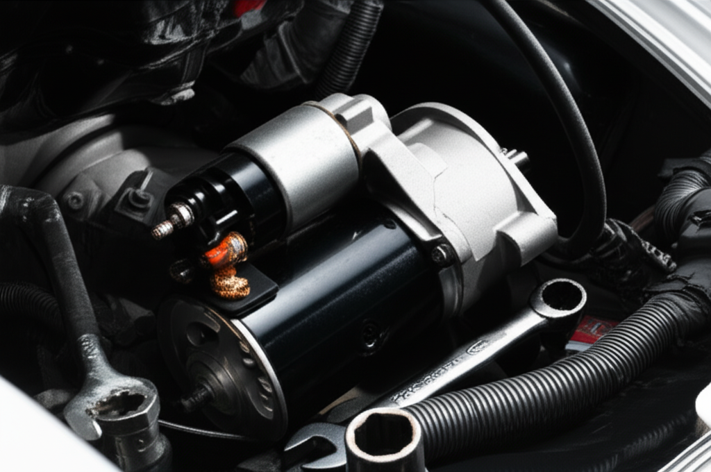
Automotive Starter Motors
Starter motors live in a different world. They deliver huge torque for a few seconds, then they rest. They often use brushed DC designs with a laminated armature and field structure. The lamination choices still matter even though duty cycles are short and battery health often dominates failures.
- Materials. Cost‑effective NOES laminations with gauges chosen for mechanical robustness and manufacturability. You do not chase the thinnest gauge since electrical frequency and duty are modest.
- Processes. Stamping and interlock or rivet stacks for armatures. Welding where needed for carriers. Bonded stacks appear in premium designs where acoustic and balance targets rise.
- Design notes. High current pulses heat the core fast. Good stacking pressure and coating help control hot spots and prevent buzz. You must also protect the coil and commutator from debris given the environment.
If you troubleshoot starters you know many “starter motor problems” start with the battery, poor grounds, or the solenoid. Engineers designing starters can use the same insight. Keep the current path low resistance and keep heat under control. The lamination stack lives inside a system that includes the bendix gear, ring gear, brushes, commutator, solenoid, and thermal soak from the engine. A core that runs efficient under load reduces temperature spikes which helps brush life and lowers the odds of a burning smell under the hood.
A few terms you may hear in the field and how they map to design choices:
- Grinding noise when starting. Often ring gear or bendix engagement, not lamination issues. Yet repeated mis‑engagement can transmit shock into the armature and stack.
- Slow crank or intermittent starting. Low voltage due to cable drop or battery, or high current draw from worn brushes. A hot armature due to excess iron loss can aggravate the symptom.
- Starter motor brush or commutator wear. Heat and vibration shorten life. A balanced, rigid armature stack helps here.
- Starter motor armature repair or bendix replacement. Field service language for what you influence with better materials, lower vibration stacks, and good process control.
You can reduce warranty returns even on a cost‑sensitive starter when you get the fundamentals right. That means honest material selection, stable stamping processes, and stacks that stay tight for the life of the vehicle.
Specifying What You Need: A Practical Sourcing Checklist
You will save time and avoid surprises if you hand your supplier a clear, testable specification. Use this as a starting template and adjust to your application.
- Material and grade
- Specify NOES grade and thickness by standard designation. Include acceptable alternates by thickness and grade band.
- For specialized alloys call out cobalt or nickel content and supplier options.
- Insulation coating
- Specify by ASTM A976 class and minimum surface insulation resistance. State if post‑cut anneal is required and whether the coating must survive it.
- Lamination thickness and stack height
- Define thickness tolerance and target stacking factor for assembled cores.
- Loss targets
- State maximum core loss at your operating flux density and frequency with the IEC 60404 test method reference. Include a second point if your duty has two peaks, for example base speed and field weakening speed for traction drives.
- Cutting process and burr limit
- Define acceptable processes for prototypes and production. Set a burr height limit and where burr should face relative to flux and slot insulation.
- Flatness, camber, and concentricity
- Set limits that protect your air gap and acoustic targets.
- Stacking and bonding
- Specify the stacking method, whether bonded, interlocked, welded, or riveted. Define allowable weld location zones away from high flux regions.
- Mechanical fixation and torque
- Set torque specs for tie rods or end plates. Define any features that must remain stress free.
- Anneal requirements
- Define atmosphere, time, and temperature ranges when needed. State handling precautions and QC checks post anneal.
- Dimensional tolerances and GD&T
- Include critical features like tooth width, slot opening, and OD/ID runout with appropriate tolerances and datum schemes.
- QA and sampling plan
- Specify incoming inspection, lot traceability, and sample size for loss testing. Include capability requirements where your design demands consistency.
- Test coupons and witness samples
- Request Epstein strips or ring samples cut alongside production to validate properties.
- Cleanliness and packaging
- Specify allowable contamination and rust prevention. Call out bagging, interleaves, and stacking orientation to protect coating and flatness in transit.
- Compliance and certifications
- Ask for ISO 9001 or IATF 16949 where appropriate. Require material certs that trace grade, coating, and heat.
- Change control
- Lock down process variables that affect loss. Require PPAP or equivalent for any change in material, coating, die clearance, or bonding process.
If this looks long, remember you are buying performance, not just steel shapes. Clear specs empower your supplier and protect your program.
Tolerance, QA, and Test: How to Verify What You Bought
You do not need a full magnetics lab to manage quality on motor laminations. You do need a few reliable checks and a plan.
- Dimensional checks. Use optical or CMM methods for tooth width, slot geometry, and concentricity. Verify burr height with a standardized method.
- Stack checks. Measure stack height versus lamination count to confirm stacking factor. Check flatness and parallelism under light clamping forces.
- Electrical checks. Verify surface insulation resistance of coatings at incoming inspection. Spot check assembled stack interlaminar resistance if bonding performance worries you.
- Core loss verification. For critical programs request supplier Epstein results at your points. If you need in‑house checks consider a ring core test for quick trend validation even if it is not an absolute number.
- Vibration and noise. Run a modal or simple tap test on bonded versus interlocked stacks to confirm stiffness. You can catch loose stacks before they become an NVH issue.
Standards and references help you anchor the test plan. The IEC 60404 series covers magnetic property measurements. ASTM A976 helps you classify and specify coatings. ASTM A677 and ASTM A876 give language for NOES and grain‑oriented steels. You can also pull test methods and acceptance criteria from internal corporate standards or industry segments like automotive where PPAP and control plans are common.
Cost, Lead Time, and Risk: What Procurement Should Watch
Engineering wants lower loss and higher efficiency. Procurement wants predictable cost and lead time. Both win when you manage three levers.
- Tooling strategy
- Progressive dies cut piece price though they add NRE and lead time. Laser or EDM keeps you agile at low volume. Align the tool plan with ramp rate and design stability.
- Material flexibility
- Lock a primary grade, then list qualified alternates by thickness and grade band. Avoid single‑source risk for critical programs unless you have a strong reason.
- Process control
- Hold your suppliers to burr height, flatness, and bonding specs with simple gauges and SPC. A little discipline on these variables saves big money on scrap and rework.
Expect material price volatility in specialty grades and cobalt alloys. Plan buffers for thin gauges or rare coatings. For bonded stacks, factor cure time and fixture capacity into lead time. For welded stacks, plan for QA on HAZ and distortion.
Cost savings ideas that do not hurt performance:
- Optimize lamination nesting and grain orientation to raise coil yield while keeping performance stable.
- Relax non‑critical tolerances and move from EDM to laser for prototypes where HAZ does not affect your test goal.
- Use interlock plus a targeted adhesive stripe to gain stiffness without full‑surface bonding when budget is tight.
Your Engineering Takeaway and Next Steps
You now have a clear map. Lamination performance comes from the trio of material, thickness, and process. Get all three right and your motor hits efficiency targets without drama. Get them wrong and you chase heat, noise, and schedule slips.
Key points to remember
- Thinner, well‑insulated laminations reduce eddy currents and cut core loss at higher electrical frequency.
- Manufacturing stress and burrs raise loss. Plan for low‑damage cutting and stress relief when needed.
- Bonded stacks often give the best acoustic and loss performance though they demand process control.
- Match material and gauge to application. Do not over‑spec your starter motor or under‑spec your traction drive.
- Specify coatings by standard class and test core loss at your actual operating frequency and induction per IEC 60404.
Actionable next steps
- Define your operating window. List the electrical frequency and flux density points that matter for your duty cycle.
- Shortlist two lamination gauges and two coatings. Ask suppliers for loss data at your points and for samples you can test.
- Choose a prototyping path. Use laser plus anneal or wire EDM to validate geometry and performance before you cut tools.
- Lock a stacking strategy early. If NVH and efficiency matter choose bonded stacks and define cure, pressure, and QA upfront.
- Write a clear spec. Use the checklist above. Ask for Epstein or ring test coupons cut from the same coil and process.
If you want a quick refresher while you compare options, bookmark the product references for stator core lamination, rotor core lamination, electrical steel laminations, and the overview on motor core laminations. They give you a fast way to align terminology and part families with your suppliers.
A final word on starter motors and “fixing” them
Many search queries focus on how to fix a car starter motor. Engineers and procurement can take a lesson from the field. Most “bad starter” symptoms trace back to the system. Low voltage from corroded battery terminals or a tired battery, high resistance grounds, or a failing starter relay often masquerade as a dead starter. Intermittent grinding noise points to bendix and ring gear issues, not lamination problems. When you build starters, keep those realities in mind. Design for low iron loss so heat stays in check during slow crank events. Build rigid, balanced armature stacks so brushes and commutators live long despite shock loads. You cannot prevent every solenoid click with no crank symptom in the field, yet you can reduce the chances that your lamination stack ever becomes the root cause.
You do not need exotic materials to earn trust in the market. You need the right lamination thickness and coating for your frequency, a stable cutting and stacking process, and a spec that keeps all parties aligned.
If you want to discuss a specific geometry, frequency target, or bonding approach, bring your duty cycle and a simple drawing. We can review your loss budget and outline a low‑risk path from prototype to production without hand‑waving.
Sources and standards to consult
- IEC 60404 series for magnetic property measurements and test methods
- ASTM A976 classification for insulating coatings on electrical steel
- ASTM A677 for fully processed non‑oriented electrical steel
- ASTM A876 for grain‑oriented electrical steel
- IEEE motor test references for system‑level efficiency and loss breakdowns
With a clear spec and the right partners, you can ship a cooler, quieter motor that hits its targets on time and on budget.