Motor Laminations Made Clear: How to Choose Materials and Processes for High-Performance Motors
Every design engineer faces the same balancing act. You want higher efficiency, lower heat, tight tolerances, and a cost that won’t wreck your BOM. If you’re weighing lamination thickness, coatings, and cutting processes because your torque density target is bumping up against thermal limits, you’re in the right place. We’ll walk through the physics, the trade-offs, and the practical decisions that separate a good motor from a great one.
Let’s keep it real and useful. I’ll explain what’s happening inside your laminated core in plain terms. I’ll show where material grades and processes make a measurable difference. I’ll also use a familiar application — the automotive starter motor — to ground the theory in the kind of constraints you actually manage.
Before we dive in, here’s a quick roadmap.
In This Article
- Why Lamination Material Choice Is Critical
- Understanding Core Losses: Eddy Currents and Hysteresis
- What is a Starter Motor in a Car? (A practical lens on laminations and design)
- Your Options Explained: Materials, Coatings, and Stack Construction
- Manufacturing and Assembly Processes: Stamping vs Laser Cutting and Beyond
- Which Application Is This For? Picking the Right Path by Use Case
- Your Engineering Takeaway
Why Lamination Material Choice Is Critical
You build magnetic circuits that convert electrical energy to mechanical power. The core limps without the right laminations. Set the basic goal like this: maximize magnetic flux with minimal loss while keeping mass, cost, and manufacturability within your constraints.
Three realities drive your lamination choice:
- Losses rise fast as frequency rises. Thinner laminations with good insulation reduce eddy currents and heat. That shows up as better motor efficiency and longer service life.
- Magnetic properties vary widely across electrical steels. Silicon content, texture, and processing change magnetic permeability and core loss. Think of permeability like a sponge for magnetic flux. A soft magnetic material soaks up flux easily. A poor one resists it and wastes energy as heat.
- Manufacturing creates or controls defects. Burrs, stress, and insulation damage increase loss and reduce repeatability. You can design a perfect stack on paper. A rough punch or improper anneal can erase the gain.
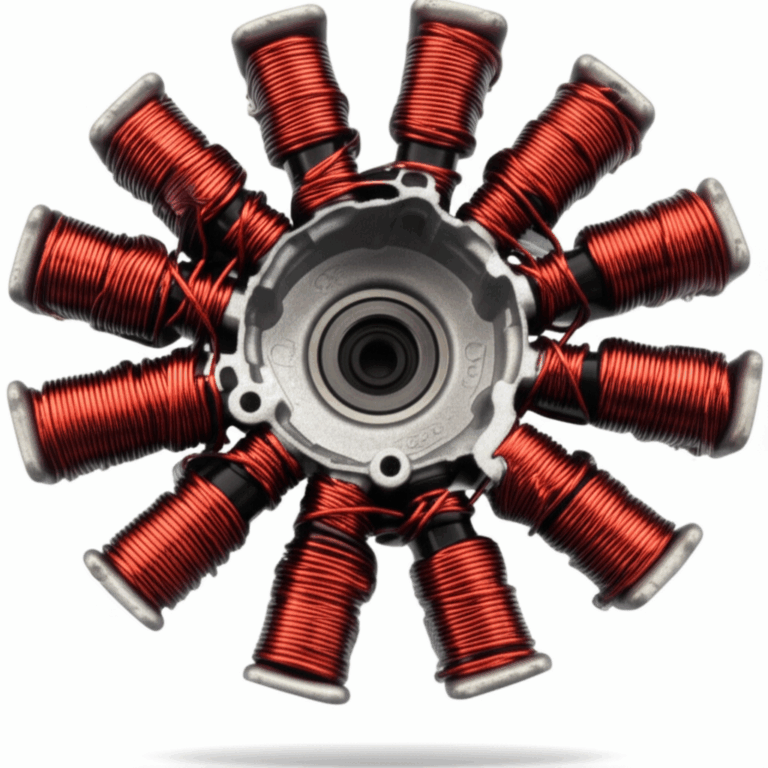
A laminated core is not a commodity block of steel. It’s a precision magnetic component. If you need a quick primer on the building blocks and why they matter, start with a clear definition: motor core laminations are thin, insulated sheets of electrical steel stacked to form the stator and rotor. The insulation blocks current between layers which slashes eddy-current loss while the steel carries the magnetic flux that produces torque.
Understanding Core Losses: Eddy Currents and Hysteresis
Two losses do the heavy lifting here.
- Eddy current loss: Picture water flowing down a river that suddenly hits a bend. Swirls form. In your core, a changing magnetic field induces circular currents inside the steel. Those loops waste power as heat. Thinner laminations with good interlaminar insulation break the big swirls into tiny ones. Less swirl, less heat.
- Hysteresis loss: Magnetize a soft magnetic steel. Now reverse the field. The material doesn’t snap back instantly because the magnetic domains lag. That lag shows up as energy loss across the B-H loop. Materials with lower coercivity — which is the resistance to being demagnetized — have lower hysteresis loss.
What dials these losses up or down?
- Frequency: Higher frequency increases both losses. Eddy currents grow roughly with the square of lamination thickness and frequency. That is why high-speed BLDC machines and high-frequency alternators lean on thinner gauges.
- Flux density: Higher B increases both losses nonlinearly. You can’t cheat physics. Oversaturate the core and you pour watts into heat.
- Material choice and processing: Steel grade, grain orientation, and the final anneal set the microstructure. That microstructure governs permeability, coercivity, and loss.
If you’re designing around high current draw during start — think 100 to 400 amps for automotive starting systems on a 12-volt DC bus — heat rises fast during cranking events. Lower core loss buys real thermal headroom. It also protects winding insulation and magnet adhesives which extends service life.
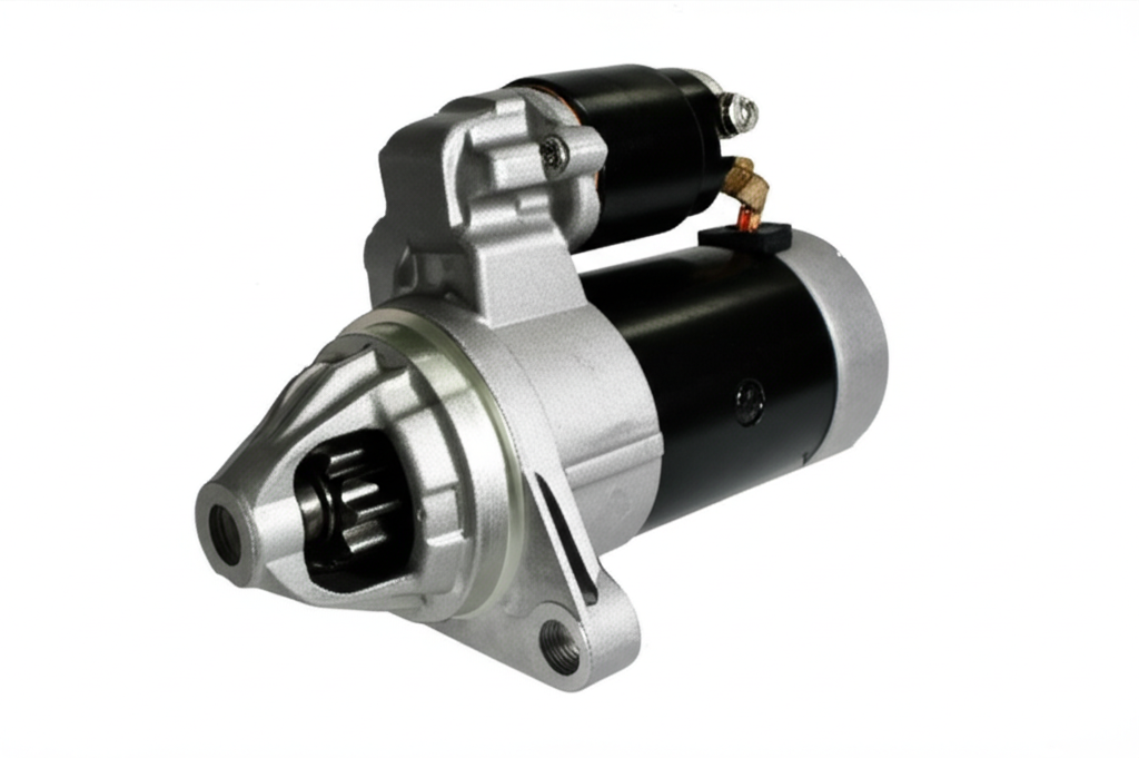
What is a Starter Motor in a Car? Your Guide to Engine Ignition
Let’s use the automotive starter as a concrete example. This application brings big current, short duty cycles, and rugged cost targets. You see the full system challenge here which makes it a great case to ground your lamination choices.
The Essential Role of the Starter Motor in Your Vehicle
A starter motor is a powerful electric motor that initiates engine combustion. It converts battery energy into mechanical torque that cranks the engine so fuel and ignition can take over. It’s different from the car battery which supplies energy and from the alternator which recharges the battery after the engine runs.
You’ll see two main architectures in the field:
- Direct drive starter: The motor’s pinion gear drives the flywheel ring gear at roughly motor speed. It’s older and robust.
- Gear reduction starter: The motor runs faster through a reduction gear train which increases torque at the pinion while allowing a smaller motor. Many late-model vehicles use this because it improves power density and cold-start performance.
Permanent magnet starters are common because they reduce size and weight. Others use wound field coils for robust thermal behavior and field weakening under stall.
How a Starter Motor Works: The Engine Starting Sequence
- Activating the starter circuit:
- You turn the key or press the start button. The ignition switch energizes the starter relay which applies current to the starter solenoid.
- Current flows from the 12-volt car battery to the solenoid coil which pulls in a plunger.
- Solenoid’s dual action: Engaging and powering
- The solenoid moves a lever that pushes the pinion gear forward to mesh with the flywheel ring gear.
- At full travel the solenoid closes a high-current contact. That contact completes the circuit that feeds the starter motor armature.
- Cranking the engine and disengagement
- The starter spins. The armature turns the Bendix drive and pinion which rotates the flywheel and crankshaft.
- The engine fires. An overrunning clutch inside the drive lets the pinion freewheel so the engine doesn’t back-drive the motor. The solenoid drops out which retracts the pinion.
That’s the mechanical ballet. The laminated rotor and stator inside the starter motor shape the magnetic field during this event. That field translates battery current into torque at the pinion. Thinner laminations and clean stack construction keep I2R heating in the windings from being compounded by core loss which prevents smoke and burning smell during cranking.
Key Components of a Starter Motor
- Starter solenoid: It acts like a relay and a linear actuator. It engages the gear and closes the high-current path to the motor.
- Electric motor: The heart of the system. It includes an armature with a laminated core, a commutator, brushes, and either field coils or permanent magnets.
- Drive mechanism (Bendix drive): It includes the pinion gear and an overrunning clutch. It engages the ring gear on the flywheel during cranking and protects the motor when the engine fires.
- Housing: It mounts the assembly to the engine block near the bell housing which is where the flywheel lives.
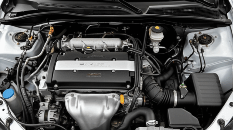
Under the hood this unit sits near the engine block at the transmission junction. Location varies by make and drivetrain. You’ll see compact starters on small engines, marine starter variants with sealed housings, and heavy duty starter designs for diesel trucks.
Common Symptoms of a Failing Starter Motor
You can hear and smell a lot here. Each symptom hints at a physical root cause.
- Clicking sound but no engine crank: You hear a single click if the solenoid engages yet the motor doesn’t spin. A weak battery or a stuck armature can do this. Multiple rapid clicks point to low battery voltage or high resistance at the battery terminals.
- Car no click no start: No sound from the solenoid suggests a dead battery, a faulty ignition switch, a neutral safety switch issue, or a bad relay.
- Grinding noise when starting: The pinion fails to mesh with the ring gear. You may have worn teeth on the pinion gear or damage on the flywheel ring gear.
- Whining noise starter: The starter free-spins because the overrunning clutch has failed or the pinion doesn’t engage the ring gear.
- Slow cranking or engine turns over slowly: Voltage drop under load, worn brushes, a weak armature, or corroded grounds can cause sluggish cranking.
- Smoke from starter or a burning smell: Overheating from a locked rotor, a shorted armature winding, or prolonged cranking.
- Intermittent starter issues: The car starts sometimes then doesn’t. Loose starter wire, corroded battery terminals, or a failing solenoid can fit this pattern.
You want to separate starter faults from other no-start causes. Alternator vs starter confusion shows up because a weak alternator leaves a low battery that can’t deliver the starter motor current draw. Crankshaft position sensor or fuel pump relay failures prevent combustion after cranking which feels different. Listen to the engine. If it cranks at normal speed and never fires you likely have a fuel or ignition problem rather than a starter.
Basic Troubleshooting Steps for Starter Motor Problems
- Check the car battery: Measure open-circuit voltage and perform a battery load test. Clean and tighten battery terminals. Try a jump start or a car battery charger to bring the system back to life.
- Listen carefully: A single click points to a solenoid or battery issue. Multiple clicks often mean low voltage from a weak battery or bad connections.
- Inspect wiring and grounds: Look for a corroded ground wire or a damaged power cable. A loose starter wire or a frayed starter motor wiring harness drops voltage under load.
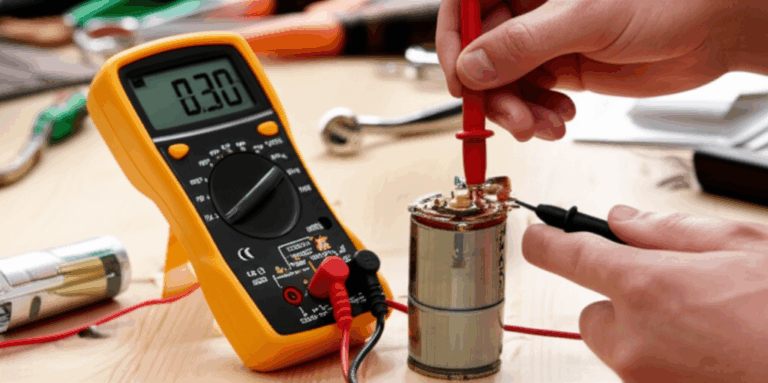
- Test the starter relay and fuses: Use a multimeter. Command the relay and verify continuity and voltage at the solenoid S terminal.
- Bench test the starter motor: Remove it if accessible. Spin it on the bench while measuring no-load current and look for smooth engagement. A multimeter or a current clamp helps you check starter motor current draw.
Cold start issues exaggerate electrical weaknesses because chemical reactions in the battery slow down. Hot start problems can point to heat soak and marginal clearances in bushings or solenoid plunger binding.
Starter Motor Lifespan, Maintenance, and Replacement
- Lifespan: Five to ten years or roughly 100,000 to 150,000 miles is common in passenger vehicles. Frequent short trips and extreme temperatures reduce life.
- Common failure modes: Worn brushes and commutator segments lead the pack. Solenoid failure is next. Bendix drive wear shows up as grinding or free-spinning. Electrical shorts or contamination round out the list.
- Replacement cost: Parts can range from remanufactured units at $60 to new OEM north of $500 on luxury models. Labor varies with access. A small transverse engine with an easy-to-reach starter sits near the low end. Others hide under intake manifolds or behind subframes which drives labor higher.
When you spec or buy starters from Bosch, Denso, Valeo, ACDelco, and other market leaders, you’re buying the same fundamentals. A laminated core built from the right electrical steel with controlled burrs and a proper insulation coating. This is where our focus on laminations pays off.
Your Options Explained: Materials, Coatings, and Stack Construction
Here’s the balanced view. No single material wins everywhere. Your application frequency, temperature, and cost target pick the winner.
Material considerations
- Non-oriented silicon steels (NOES), M-grades:
- Best for general-purpose motors and automotive starters. These grades trade cost and magnetic performance well at 50–400 Hz equivalent flux frequency ranges.
- Pros: Widely available, good permeability, reasonable core loss, predictable stamping behavior.
- Cons: Higher losses than specialty alloys at high frequency, properties vary with supplier and processing.
- See typical options and formats under electrical steel laminations.
- Grain-oriented silicon steel (GOES, CRGO):
- Designed for transformers where the flux runs along the rolling direction. It shines in static transformers and EI/UI core transformers rather than rotating motors because flux in motors rotates which breaks the orientation advantage.
- Pros: Very low core loss in the rolling direction. Great for transformer lamination core designs.
- Cons: Poor off-axis performance in motors. Use GOES for transformer applications rather than rotating machines.
- High-silicon steels and low-cobalt alloys:
- Push a bit more performance for higher speed machines. Increased silicon improves resistivity which reduces eddy currents.
- Cobalt-iron alloys:
- Serious power density for aerospace and high-speed machines. High saturation flux density allows more torque in the same package.
- Pros: High saturation, good high-frequency behavior with thin gauges.
- Cons: Expensive, supply chain complexity, more difficult to stamp which can raise burrs and stress unless controlled.
- Powdered iron cores:
- Useful for very high frequency with 3D flux paths. Not typical for starter motors which stay at relatively low electrical frequencies during cranking. These cores see use in some specialized BLDC machines and inductors.
- Permanent magnet considerations:
- If your starter uses permanent magnets for the stator field, watch thermal demagnetization limits. Lower core loss reduces internal temperatures which protects magnet strength under repeated crank cycles.
Insulation coatings and stack factor
- Coating class matters: Organic and inorganic coatings insulate laminations from each other. They block interlaminar eddy currents and let you press stacks without shorts.
- Stack factor: The ratio of steel to overall stack thickness affects your effective slot fill and magnetic cross section. Thin coatings slightly reduce stack factor yet dramatically cut eddy currents which wins at higher frequency.
- Thermal class: Coating thermal stability should match your operating environment. Starters see short high-temperature spikes during cranking which argues for coatings that keep dielectric strength at elevated temperature.
Stator vs rotor lamination selection
- Stator cores experience alternating flux under stationary mechanical conditions. Focus on low core loss and rigidity for slot stability. Explore options like stator core lamination to see how tooth geometry, back iron thickness, and interlocks affect performance and assembly.
- Rotor cores turn inside the field and see rotational stresses. Watch balance, skew options for noise reduction, and tight control of shaft fit. If you build gear reduction starters with high-speed rotors, rotor lamination integrity is critical. See examples of rotor core lamination strategies that minimize eccentricity and cogging.
Manufacturing and Assembly Processes: Stamping vs Laser Cutting and Beyond
You have three main ways to make laminations. Each one trades speed, precision, and edge quality.
- Progressive die stamping:
- The high-volume workhorse. Great for large production runs with repeatable accuracy and excellent part-to-part consistency when tooling is right.
- Pros: Lowest cost per part at scale, high speed, integrated interlocks, and low per-piece handling.
- Risks to manage: Burrs raise interlaminar shorts and core loss. Tool wear increases dimensional drift and burr height. You must control lubrication and clean parts to avoid contamination.
- Design note: Add chamfers and fillets that align with tooling strength. You avoid microcracks that become stress risers.
- Laser cutting:
- Ideal for prototypes and low-volume builds with complex geometry. No tooling lead time. Small feature changes cost little.
- Pros: Flexible, precise, quick to iterate.
- Cons: Heat-affected zone (HAZ) can harden edges and raise local loss. You can mitigate with post-cut annealing and by tuning laser parameters. For high-volume production with simple profiles a stamped part often wins on cost.
- Wire EDM:
- Very precise with minimal burrs. Slow and expensive. A fit for highly specialized rotors or stator segments where tolerance dominates cost.
Stack construction options:
- Interlocking tabs:
- Think LEGO-like lances that snap adjacent laminations together. They create rigid stacks without weld heat which protects magnetic properties.
- Pros: No adhesives, fast stacking, good alignment.
- Cons: Slightly lower stack factor, possible local mechanical stress.
- Bonding (varnish or adhesive):
- Bonds laminations into a monolithic stack. Excellent for noise and vibration because it damps interlaminar movement.
- Pros: High stack factor, lower acoustic noise, improved mechanical integrity.
- Cons: Process control matters. Cure schedule and cleanliness drive bond strength. Adhesives add cost.
- Welding:
- TIG or laser tack welds at the OD or ID. Fast and strong. Heat can locally raise loss unless you use minimal energy and smart placement away from peak flux regions.
- Riveting or cleating:
- Mechanical fasteners keep stacks aligned. Use with caution to maintain magnetic cross section.
Post-process annealing:
- Stress relief anneal can restore magnetic properties after cutting. It reduces work hardening from stamping or the HAZ from laser cutting. Control atmosphere and temperature carefully to preserve coating integrity and to avoid oxidation.
Skew and noise:
- Skewing rotor or stator slots reduces cogging torque and acoustic noise. It also changes effective slot harmonics which affects back EMF and torque ripple.
Metrology and quality:
- Measure burr height, insulation resistance between laminations, and stack squareness. Track variation because bursty quality shows up as bursty motor efficiency on the dyno which frustrates both design and production teams.
Which Application Is This For? Picking the Right Path by Use Case
You seldom design in a vacuum. Let’s match choices to common applications.
- Automotive starter motor:
- Profile: High current draw at 12-volt, short duty cycles, low duty factor, wide temperature swings. Gear reduction starter variants run higher speed which pushes lamination loss at the rotor.
- Material: NOES silicon steel in thin gauges is the workhorse. Permanent magnet starters use NOES in the armature. Wound field starters use laminations in both stator and rotor. Favor coatings with good dielectric strength and thermal stability.
- Manufacturing: Stamping with interlocks balances cost and performance for volume. Use adhesive bonding to reduce rattle and noise if NVH is tight.
- BLDC stator core for auxiliary pumps or fans:
- Profile: Higher electrical frequency at moderate currents. Efficiency targets are rising due to CO2 and fuel economy rules.
- Material: Thinner NOES or specialized low-loss grades. Some designs justify cobalt-iron for extreme speed. Control skew and slot shape to manage torque ripple. For deep dive content see the structure and role of a BLDC stator core through dedicated resources.
- Industrial motors and compressors:
- Profile: Continuous operation where losses add up. Temperature rise drives lifecycle costs.
- Material: Lower loss NOES grades pay back through efficiency standards like IE3 and IE4. Bonding can cut noise in HVAC and compressors.
- Small engine starter motor and marine starter:
- Profile: Exposure to vibration, moisture, and salt. Sealing is critical. Duty cycles mirror automotive yet with harsher environments.
- Material: Corrosion-resistant coatings and robust bonding. Avoid welding near flux paths to keep loss low.
- Transformers and power electronics:
- Profile: Static or low-frequency flux. You don’t rotate flux by 360 degrees like a motor.
- Material: Grain-oriented silicon steel shines for low core loss along the rolling direction. Explore EI and UI cores for cost-effective power devices. Transformers live in a different lamination world than motors.
Where do you sit on the volume curve?
- Prototype to pilot runs:
- Use laser cutting for speed. Plan a later move to stamping. Expect small differences in loss after stress relief.
- High volume production:
- Invest in progressive dies. You pay once for tooling. You get high throughput and consistent interlock features. Integrate upstream QA to catch burr growth early.
Procurement Perspective: Tying Performance Targets to Supplier Specs
You want to buy performance not just metal sheets. Ask for and verify:
- Guaranteed core loss at your intended flux density and frequency. The test point matters. A loss spec at 1.0 Tesla and 50 Hz may not reflect your rotor at 1.4 Tesla and higher harmonics.
- Sheet thickness tolerance and coating class with dielectric strength data.
- Maximum burr height and typical distribution. Include limits by edge orientation because axial burrs often do more damage in stators with tight slot liners.
- Post-cut anneal capability and atmosphere control if you laser cut. Confirm coating survivability after anneal.
- Stack factor and interlock geometry. Evaluate how that impacts slot fill and winding process.
- Traceability to coil lot and heat. Magnetic properties can shift slightly by heat and coil position.
Leverage supplier domain knowledge. The right team understands both raw material standards and the realities of stacking, bonding, and machining. You can speed up DFM, reduce scrap, and stabilize your PPAP submissions.
Design Notes Through the Starter-Motor Lens
We promised you practical guidance. Let’s connect some common starter design questions to lamination choices and system behavior. This also lets us integrate many of the diagnostic terms you hear in the field.
- Engine cranking noise and NVH:
- Metal-on-metal grinding during engagement is a mechanical issue at the pinion or ring gear. That said a skewed rotor and optimized slot combination can cut electromagnetic whine during spin-up. Lambdas on skew improve acoustic signature so your whining noise starter complaint drops.
- Battery vs starter motor confusion:
- A weak battery drives slow cranking and low system voltage. That increases armature current which increases copper I2R loss and heats the core. Better laminations won’t fix a dead battery yet they give thermal margin that prevents damage during marginal starts.
- Hot start problems:
- Heat soak raises resistance in windings and reduces magnet strength in permanent magnet starters. Lower core loss reduces internal temperature rise during each crank cycle which buys you reliable restarts after a long drive.
- Intermittent starter issues:
- You know electrical faults often masquerade as mechanical failure. A neutral safety switch or immobilizer starter issue blocks the start command. If the motor doesn’t receive current you can’t blame laminations. Still design for graceful thermal behavior so repeated “try again” attempts don’t cook the core.
- Testing starter motor current draw and voltage drop:
- Measure battery voltage drop during start. A healthy system shows a predictable sag under load. Excessive sag points to battery health or bad connections. Current draw above normal with slow cranking suggests a tight engine or a dragging starter bush which is a mechanical issue. Normal current with no motion suggests an internal mechanical bind.
You can see how lamination decisions serve as the foundation. They won’t solve every starter symptom. They will set efficiency, temperature margin, and acoustic behavior which ripple through reliability and customer satisfaction.
Practical Guide to Tolerances, QA, and Documentation
Be explicit in drawings and supplier SOWs:
- Material callout: Grade, thickness, and coating class with equivalent standards accepted from multiple mills.
- Magnetic test plan: Specify Epstein or single sheet tester data acceptance with your target flux densities.
- Burr limits: State maximum burr height and direction. Require regular burr coupons from tools.
- Insulation resistance: Set a minimum interlaminar resistance per unit area. Verify after forming or stacking.
- Stack assembly: Define interlock locations, adhesive type and thickness, or weld count and placement. Include skew angle if used.
- Balance: Rotor lamination stack must support final balance targets with plugs or drilled balance features. Document where material removal is allowed.
Keep a clean manufacturing environment. Oil and particulate on lamination surfaces degrade adhesive bond strength. They also cause hot spots where insulation fails which can raise eddy currents locally.
A Short Word on Stators, Rotors, and Transformers
Each laminated assembly behaves a bit differently:
- Stators carry alternating flux with stationary mechanical conditions. The tooth tips and back iron thickness dominate magnetic stiffness and slot leakage. If you want a deeper dive into stator-specific decisions, review proven practices in stator core lamination.
- Rotors store and deliver energy with multiple design options like skew, saliency, and cage topologies for induction machines. Automotive starters use laminated armatures with commutators that live and die by consistent slot geometry and low burrs. See examples under rotor core lamination.
- Transformers route flux mostly along a single axis. Grain-oriented steels with EI or UI stacks win there. Their loss profile is unmatched in the rolling direction. Motors need isotropic behavior which is why non-oriented steels dominate.
Source Reality: Standards and Credible References
Anchor key decisions against recognized references rather than hearsay:
- IEC 60404 series: Magnetic materials — methods of measurement and property definitions.
- ASTM standards for electrical steels and insulation coatings. These define chemistry, thickness, and magnetic testing best practices.
- SAE and OEM specifications for automotive electrical machines which cover validation, salt spray, vibration, and thermal cycling.
- IEEE Transactions on Magnetics and recognized conference proceedings for the latest on loss modeling and lamination processing.
You don’t need a library card to move forward. You do need to hold suppliers to consistent data reporting and to verify at your conditions.
Your Engineering Takeaway
Here are the big points to keep in your pocket:
- Laminations exist to kill eddy currents and to guide flux efficiently. Thinner gauges with robust coatings reduce loss at higher frequency which boosts efficiency and lowers heat.
- Material selection is application dependent. NOES silicon steels fit most motors and automotive starters. Cobalt-iron alloys earn their keep in high-speed, high-power-density designs.
- Manufacturing matters. Stamping wins on cost at volume. Laser cutting wins on speed for prototypes. Control burrs, stress, and insulation damage because they directly raise core loss.
- Stack construction changes noise and integrity. Interlocks are fast and clean. Bonding improves damping and stack factor. Welding must be minimal and smartly placed.
- In starter motors the laminated armature and stator underpin torque, thermal margin, and acoustic behavior during cranking. Good laminations don’t fix a dead battery. They do prevent overheating that turns a simple electrical issue into a mechanical failure.
- Specify what you need with measurable limits. Core loss at your B and frequency. Burr height. Insulation resistance. Stack factor. Anneal details. Then audit it.
If you want a quick sanity check on your current design, compare your material and thickness against typical specs for volume-made electrical steel laminations. Next, review how you construct your stator and rotor stacks against proven architectures for motor core laminations. Small changes there often unlock both efficiency and manufacturability.
Ready to refine the spec? Share your target torque, speed, duty cycle, frequency content, temperature limits, and volume expectations. With that we can recommend a lamination grade, thickness, coating, and manufacturing route that hits your performance goals without blowing up your cost or lead time.