Motor Laminations Made Clear: How Material and Process Choices Drive Performance, Cost, and Reliability
Every design engineer runs into this sooner or later. You need a motor that hits a target efficiency, fits a tight envelope, and still comes in on budget. You tweak copper fill, magnet grade, and slot geometry. Yet the core runs warm, audible losses creep up, or cost per unit balloons at volume. Often the key sits right in the middle of the machine: the lamination material, thickness, coating, and stacking method. Get lamination choices right and you unlock higher efficiency, cooler operation, lower magnet mass, quieter NVH, and a cleaner supply chain. Get them wrong and you burn watts and dollars.
This guide answers the practical questions engineers, product designers, and procurement managers ask about motor core laminations. We’ll break down the physics in plain language, compare material and manufacturing options with pros and cons, and help you match solutions to your application. To ground the discussion, we’ll also zoom in on a familiar automotive example: the windshield wiper motor. You’ll see how lamination decisions show up in field performance and even in DIY replacements, from slow wipers to frozen blades that stress the motor.
Use this as your playbook to make clear, confident decisions and run a better conversation with your lamination supplier.
In This Article
- Why Lamination Choice Is Critical
- Core Losses Explained: Eddy Currents and Hysteresis
- A Guide to Common Lamination Materials
- Manufacturing and Assembly Processes That Matter
- Match the Solution to the Application
- Spotlight: Automotive Windshield Wiper Motors — Design to Field Service
- Cost, Quality, and Procurement Considerations
- Testing and Validation You Can Trust
- Your Engineering Takeaways and Next Steps
Why Lamination Choice Is Critical
Problem
You need to maximize motor efficiency and power density without blowing through cost targets. At the same time your team has to meet thermal, NVH, and reliability goals. Laminations sit at the heart of all of it. Yet material shorthand like “M19 29 gauge” or “0.27 mm CRNGO” can feel like alphabet soup if you don’t live in core design. You need a translation.
Explain
Motor cores use thin sheets of electrical steel stacked to form the stator and rotor. Each sheet is insulated from its neighbors. That stack reduces eddy current losses in alternating magnetic fields. The right lamination thickness and grade helps the core handle higher frequency content and higher flux density with less heat, which improves efficiency and extends service life. The wrong choice wastes energy and can force you into a heavier thermal design or larger magnets.
Guide
Think through lamination choices in four parts:
- Material grade and thickness: Silicon content, grain orientation, and thickness change core loss and permeability.
- Insulation coating: Coatings set interlaminar resistance and affect stamping lubricity, stacking friction, and bonding.
- Manufacturing method: Stamping, laser cutting, and EDM drive cost, tolerance, burr, and stress.
- Stack assembly: Interlocks, bonding, welding, and rivets affect mechanical strength, NVH, and magnetic performance.
Empower
You don’t need to become a metallurgist to make a good decision. Focus on the physics that drive your losses, the speeds you run, your frequency content, and your volume. Then pick the mix of material and process that hits your performance and cost targets. We’ll show you how.
Core Losses Explained: Eddy Currents and Hysteresis
Let’s keep the fundamentals simple because that’s where most decisions turn clear.
- Eddy currents: Imagine tossing a stick in a river. You watch little whirlpools spin around it. In a motor core, changing magnetic fields create similar whirlpools of electric current in the steel. Those currents heat the core and waste energy. Thinner, insulated laminations chop big whirlpools into tiny ones so they die out quickly.
- Hysteresis: The core’s magnetic domains don’t flip for free as the field changes direction. You pay energy each cycle. The B-H loop area represents that cost. Materials with low coercivity (the resistance to demagnetization) shrink that loop and cut hysteresis loss.
- Excess or anomalous loss: Real materials aren’t perfectly uniform. Microstructure, impurities, and surface effects add a bit of extra loss, especially at higher frequencies.
What controls those losses?
- Thickness: Halve the lamination thickness and you roughly quarter eddy current losses at a given frequency and flux density. That’s a powerful lever as speed climbs or as PWM harmonics add high-frequency content.
- Grade and grain orientation: Grain oriented steels (GO) excel in transformers with unidirectional flux. Most rotating machines use non-oriented (NO) steels that handle flux at multiple angles. Higher silicon content and tighter processing lower loss and can raise cost.
- Flux density: Loss rises quickly with flux density. If your machine saturates the teeth in peaks, you’ll pay in heat.
- Frequency: Loss scales with frequency. High-speed motors, BLDC drives with high switching rates, or machines with strong harmonic content all push you to thinner gauges and better coatings.
- Stress and burr: Mechanical stress from stamping or welding can raise losses and reduce permeability. Burrs create shortcuts for eddy currents between laminations. Both hurt performance and sometimes noise.
Want a deeper dive on materials at a glance? See the role of electrical steel laminations in managing these loss mechanisms.
A Guide to Common Lamination Materials
You have several families of materials to choose from. Each brings a trade-off between performance and cost.
Silicon steels (CRNGO/CRGO, “M grades”)
- What they are: Cold-rolled, low-carbon iron with silicon to reduce loss and increase resistivity. “NO” denotes non-oriented, “GO” denotes grain-oriented.
- Where they shine: Most general-purpose motors and generators, automotive traction motors at moderate speeds, and many industrial drives.
- Pros: Broad availability, good balance of cost and performance, multiple thickness options from ~0.65 mm down to ~0.2 mm. Wide set of insulation coatings.
- Cons: Higher loss than cobalt or amorphous options at very high frequencies. Magnetic properties shift under mechanical stress.
- Callouts: Common NO grades include M36, M27, M19, M15 with thicknesses like 0.35 mm, 0.30 mm, 0.27 mm, and 0.20–0.23 mm. Grain-oriented CRGO suits transformers more than rotors or stators in rotating machines due to directional flux needs.
Cobalt-iron alloys (e.g., 49% Co Fe-Co)
- Where they shine: High power density, high temperature, and high frequency. Aerospace, turbo machinery, high-speed spindles.
- Pros: High saturation flux density, low core loss at elevated frequency, holds properties at higher temperature.
- Cons: High raw material cost, more challenging to stamp. Often needs stress relief anneal after cutting.
Nickel-iron (Permalloy variants)
- Where they shine: Very low coercivity and high permeability for sensors, magnetic shields, and specialty motor cores.
- Pros: Excellent low-loss performance at modest flux densities.
- Cons: Expensive and mechanically soft. Not a fit for most high-torque rotors.
Amorphous and nanocrystalline ribbons
- Where they shine: Transformers and some high-frequency machines.
- Pros: Extremely low core loss at higher frequencies.
- Cons: Limited geometries and more complex packaging for rotating cores.
Insulation coatings
- Purpose: Maintain interlaminar resistance to block eddy currents. Improve die lubricity and reduce galling. Set stack friction and bonding compatibility.
- Types: Inorganic, organic, or hybrid. Classified by coating thickness, thermal class, and bonding compatibility. Higher build coatings can reduce interlaminar shorts but change stack height and mechanical behavior.
For a fast overview of common choices and where they land on cost and performance, see silicon steel laminations. If you need a single hub to explore options for rotors and stators together, bookmark motor core laminations.
Manufacturing and Assembly Processes That Matter
Process choices affect losses, tolerance, cost, and lead time. Here’s how.
Stamping (progressive dies and compound tools)
- Best for: Medium to high volume, well-defined geometry, cost per piece control.
- Pros: High throughput, good repeatability, low cost at scale, controlled burr with good die maintenance.
- Cons: Tooling investment and lead time. Stamping stresses the material which can raise loss. Stress relief anneal may be beneficial for high-performance designs.
Laser cutting
- Best for: Prototyping, low volume, complex shapes, fast iteration.
- Pros: No tooling. Strong dimensional flexibility. Quick turn.
- Cons: Heat affected zones increase local loss and can affect magnetic properties. Burr control requires tuning. Post-cut anneal helps.
Wire EDM and waterjet
- Best for: Precision parts when you must minimize HAZ, or special alloys. Low volumes.
- Pros: Excellent edge quality. Minimal thermal damage.
- Cons: Slow and costly per piece.
Tolerances and burr
- Burr height matters because it can short laminations and spike eddy currents. Set a maximum burr height spec and inspect often. Typical targets range from 10–30 microns for high-performance cores, looser for commodity drives.
- Dimensional tolerances affect slot width, tooth tip geometry, and rotor-stator air gap. These drift into torque ripple, noise, and efficiency if you loosen them too far.
Stacking and joining
- Interlocking: Tabs and dimples lock laminations like LEGO bricks to build rigid stacks without adhesives. Cost effective and fast. Can introduce localized stress and slight air gaps.
- Bonding: Insulation coatings that activate with heat and pressure “glue” the stack. Smooth OD/ID, excellent NVH, and fewer localized losses. Needs cycle time and process control.
- Welding: Spot or TIG welds hold stacks securely. Good for rotors that see high centrifugal loads. Local heat can increase loss at welds. Balance weld placement to minimize performance hit.
- Riveting and cleating: Traditional, still effective for some designs and repair-friendly.
- Stress relief annealing: After cutting or welding, a controlled anneal can restore magnetic properties. Coordinate with coating type and finished dimensions.
Need a focused look at stator and rotor implications? Check these deep dives: stator core lamination and rotor core lamination.
Match the Solution to the Application
There’s no one-size-fits-all pick. Choose material and process based on motor topology, frequency content, and production plan.
- Low-speed, general-purpose AC induction or BLDC motors
- Material: CRNGO silicon steel in 0.35–0.50 mm for cost-sensitive designs. 0.27–0.30 mm for improved efficiency.
- Process: Stamping with interlocks or bonding. Progressive dies at volume.
- High-speed BLDC or PMSM machines
- Material: 0.20–0.27 mm CRNGO or cobalt-iron if flux density and temperature demand it.
- Process: Tight burr control, bonding for NVH and balance, selective stress relief.
- Automotive traction motors
- Material: Optimized CRNGO grades with coatings that support bonding. Thinner gauges to manage switching harmonics.
- Process: High-volume stamping with robust die maintenance. Bonded stacks for NVH, PPAP and IATF controls.
- Small automotive actuators, including windshield wiper motors
- Material: Cost-optimized NO silicon steel sufficient for low-voltage DC operation and moderate duty cycles.
- Process: Stamped laminations in armatures and stators. Secure rotor stack assembly for centrifugal reliability.
- Transformers and static machines
- Material: Grain-oriented steels or amorphous ribbon.
- Process: Not rotating cores yet closely related. Different loss priorities.
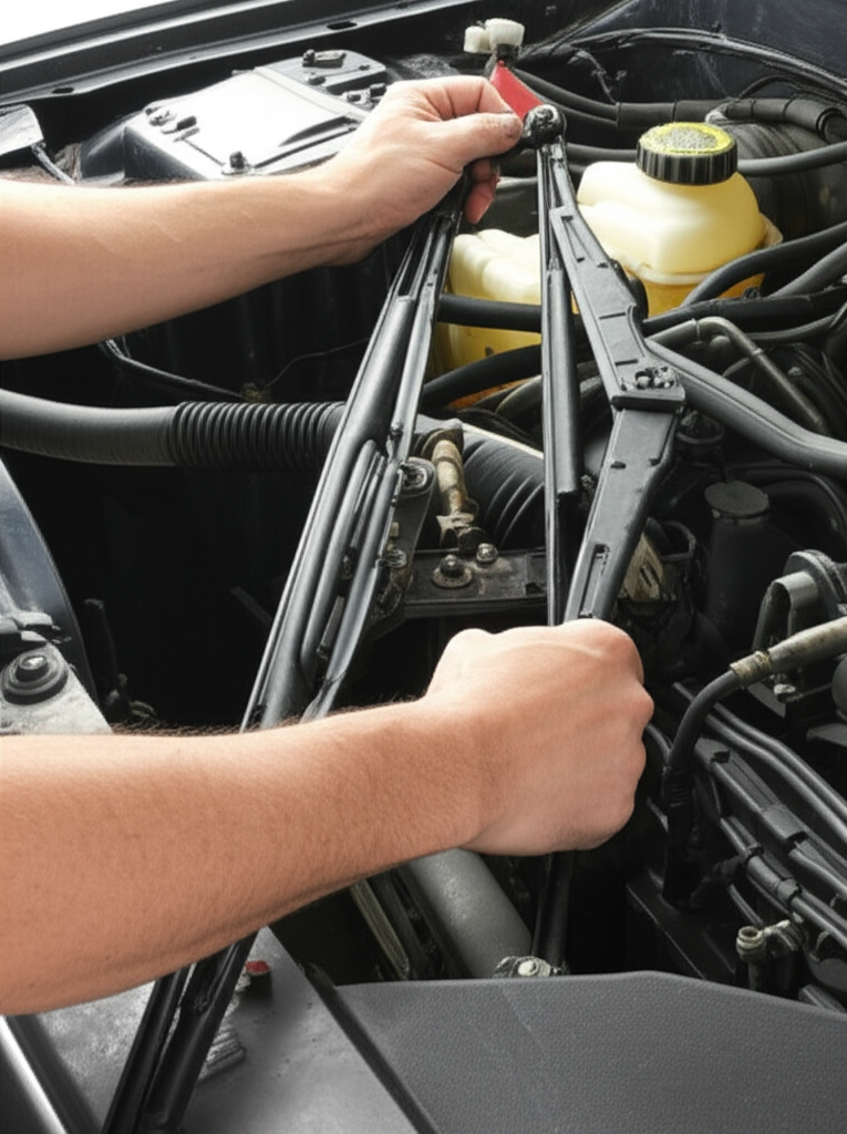
Spotlight: Automotive Windshield Wiper Motors — Design to Field Service
Why talk about wiper motors in a lamination guide? Because it’s a clear use case that links core design, manufacturing realities, and what happens in the field. A typical wiper motor is a 12 V brushed DC motor with a laminated armature, a permanent magnet or field core, and a gear reduction driving the wiper linkage. It lives near the windshield by the cowl panel where temperature swings and moisture stress it. Poor design shows up as slow, noisy, or intermittent operation and, in the worst cases, a burned-out motor after frozen wipers attempt to move.
Symptoms engineers hear from the field
- Slow wipers fix requests, wipers not moving, or noisy wiper motor repair complaints. Often these stem from increased friction in the wiper linkage, degraded lubrication, or voltage drops in the wiring harness and ground wire.
- Intermittent wiper function tied to relay issues, a failing wiper switch, or cracked solder in the Body Control Module (BCM) on vehicles that route control through it.
- Frozen wipers damage motor incidents in winter that spike current, stress the commutator, and heat the windings. Over time that can drive wiper motor burnout.
Design and material implications
- Laminated armature: The armature core uses thin electrical steel laminations to keep eddy current loss manageable under commutation ripples. You don’t run at traction-motor speeds yet PWM and brush switching still introduce frequency content that benefits from 0.35–0.50 mm laminations with good interlaminar insulation.
- Coatings and assembly: Pick a coating that supports your assembly method. Interlocking and staking deliver cost efficiency. Bonding can improve NVH and reduce buzz. Welding requires care to limit local magnetic degradation.
- Environmental protection: Seal against water ingress to avoid corrosion that can increase drag. A gasket or seal at the motor housing helps. Rust prevention around the cowl panel and linkage pays dividends.
- NVH: Uniform stack pressure and balanced armature stacks reduce noise. Tighter tolerances on rotor OD and stator ID cut eccentricity that would show up as audible drone.
Diagnostics and components that shape field outcomes
- Electrical supply: Many “bad motor” complaints trace back to power supply issues. Check the wiper motor fuse location in the fuse box, inspect the relay, measure voltage drop with a multimeter, and verify ground integrity. Use dielectric grease on connectors to protect against corrosion.
- Linkage and mechanical load: Windshield wiper linkage removal during service often shows worn bushings or seized joints. Lubricate the wiper linkage and inspect the wiper transmission for free motion.
- Control logic: Vehicles with intermittent wiper function often use a relay or BCM timing module. Failures there mimic a motor fault.
Why engineers should care about DIY replacement guides
The way technicians and DIY owners replace motors reveals design opportunities. For example, if cowl panel removal requires prying brittle trim clips, your serviceability rating suffers. If wiper arm removal demands a specialized wiper arm puller due to corrosion on splines, consider protective caps or better coatings. If installers routinely forget to reconnect washer fluid lines at the cowl, a keyed connector or colored clip might help. Manufacturing and design decisions ripple through the entire lifecycle.
Field-serviceable steps also touch many SEO phrases you may recognize. The following “engineer’s-eye” installation outline embeds real-world constraints for the wiper system, which includes the windshield, wiper arms and wiper blades, motor housing, wiper linkage, and electrical connector.
An engineer’s overview of wiper motor replacement
- Before you start
- Park the vehicle on a level surface with the parking brake set. Open the hood for access near the engine bay and windshield cowl.
- Power off before working on wipers. Disconnect the negative battery terminal at the battery to avoid shorts and accidental activation.
- Note the wiper park position. Mark the wiper arms on the windshield glass with tape so the rest position can be restored during reassembly.
- Tools and materials: socket wrench set and torque wrench, screwdriver types (Phillips and flathead), Torx bit set if applicable, trim removal tool and pliers, wiper arm puller for stuck arms, penetrating oil for stubborn bolts and nuts, clean rags, work gloves, safety glasses, dielectric grease, zip ties for the wiring harness as needed, multimeter for testing. Stock a new motor that matches the part number wiper motor spec, whether OEM or a high-quality aftermarket option.
- Access through the cowl panel
- Pop the caps on the wiper arms. Remove the retaining nuts and lift off the arms. Use a wiper arm removal tool when corrosion holds them in place.
- Remove trim clips and screws along the cowl panel or grille. Some applications require you to disconnect the windshield washer system hose and a small electrical connector.
- Lift the cowl to reveal the wiper linkage and the motor assembly. Keep track of trim clips and any weather stripping.
- Disconnect linkage and wiring
- Identify the ball joint or bolts that connect the wiper transmission to the motor crank. Carefully pry the joint or remove fasteners to free the linkage.
- Unplug the electrical connector from the motor. Inspect the wiring harness and seal for signs of heat or corrosion. Apply dielectric grease on reassembly.
- Motor removal and replacement
- Remove motor mount bolts or screws. Support the unit so it doesn’t drop and stress the linkage.
- Extract the old motor. Compare the new motor for vehicle specific wiper motor compatibility. Verify connector type, shaft length, and motor housing features.
- Install the new unit. Align it to the same orientation. Reconnect the linkage in the correct park position. Torque specifications wiper motor mounting vary by vehicle so follow service data. In general don’t over-torque which can deform the motor mount and create noise paths.
- Reassembly and test
- Reinstall the cowl panel and any trim clips. Reattach the washer hose and any small electrical items.
- Set wiper arms back on their splines to the marked position. Hand-tighten nuts first then torque to spec. Adjusting wiper arms may be necessary if park position shifted.
- Reconnect the battery. Turn the ignition to accessory. Test all modes: intermittent, low, and high. Check that wipers park correctly.
- If the wipers sweep off the windshield or park high, remove the arms and reset. If operation is noisy, verify the wiper linkage path and check for interference at the cowl.
Common post-install troubleshooting
- Wipers not moving solution: Confirm the fuse and relay. Test for voltage at the electrical connector. Verify the ground wire and continuity to the chassis. Inspect the BCM or wiper switch on the dashboard if voltage logic looks wrong.
- Wipers park in the wrong position: Reset the arms or, on some models, the park position inside the motor gear must be aligned. Always check service information for model specifics like a Honda Civic wiper motor, Ford F150 wiper motor install, Chevy Silverado wiper motor replacement, Toyota Camry wiper motor guide, Nissan Altima wiper motor fix, Jeep Grand Cherokee wiper motor notes, and similar.
- Slow or noisy operation: Lubricate pivot points. Confirm the motor mount bolts are secure without distorting the bracket. Worn wiper blades can chatter and mask root cause. Replace wiper blades while you’re there.
Cost, time, and sourcing realities
- Part cost swings with OEM vs aftermarket. You’ll see $40–$150 for many aftermarket units and $80–$300+ for OEM depending on vehicle class. Professional installation often adds 1–3 hours of labor, especially when cowl removal is complex.
- DIY time runs 1.5–4 hours for first-timers with the right tools.
- Failure modes: Wear and tear dominates. Electrical failure, water ingress through a compromised seal, and linkage seizure follow behind. Frozen wipers can burn out motors if the driver tries to run them.
Why this matters upstream
If a DIYer needs a trim removal tool, a torque wrench, and a wiper arm puller just to swap a motor, your warranty and customer satisfaction numbers will reflect it. For new designs, coordinate with service to simplify steps, reduce time to replace wiper motor assemblies, and standardize fasteners. On existing platforms, use field feedback to tune lamination stack assembly for NVH, improve sealing around the motor housing and cowl, and update installation instructions that include wiring diagram clarity and electrical connector photos.
Cost, Quality, and Procurement Considerations
Procurement managers and engineers both care about the same endgame. Predictable quality, clear cost drivers, and no surprises at PPAP.
Cost drivers you can influence
- Material grade and thickness: Higher silicon content and thinner gauges cost more yet often pay back in lower losses and magnet mass. Balance material cost against system-level savings in copper, magnets, heat sinking, and efficiency targets.
- Tooling and volumes: Progressive dies require up-front investment but provide the best piece price at volume. Laser cutting saves you at prototype and ramp phases yet costs more per part in production.
- Coating choice: Some coatings raise coil temperatures you can use in bonding. Others excel at lubricity in stamping and improve die life. Match coating to join method to avoid rework.
- Annealing: Stress relief annealing adds process cost yet yields lower loss and better permeability in high-spec cores.
- Stack method and yield: Interlocks are fast with good yields. Bonding tightens NVH and OD/ID but demands process control.
Quality controls you should ask for
- Material traceability to heat and coil number. Request mill certs with core loss and permeability stats.
- Burr height and flatness measurements with sampling plans aligned to risk.
- Core loss testing of witness rings or Epstein frame samples per IEC 60404. If you use single sheet testers for exact gauge and coating combos, record the vector conditions honestly.
- Stack height and squareness specs for both stator and rotor packs. Verify interlaminar insulation quality via resistance checks.
- Dimensional checks on slot width, tooth tip radius, and air gap features. Small changes here ripple into torque ripple and acoustic tone.
- For automotive, align to IATF 16949, production part approval process (PPAP), and specific OEM customer requirements. Confirm RoHS and REACH compliance, and if cobalt is in the mix, confirm any additional reporting.
Supplier questions that get straight answers
- What core loss data do you guarantee at my operating flux density and frequency, not just at 1.0 T 50/60 Hz?
- What is the typical and maximum burr height you hold on this geometry?
- How do you mitigate stamping stress or HAZ from laser cutting, and when do you recommend stress relief annealing?
- Which insulation coating do you propose and why? Does it support my stacking method and thermal class?
- What process controls ensure consistent stator core lamination OD and rotor core lamination ID concentricity?
Testing and Validation You Can Trust
Build confidence with test plans that catch issues early.
Material-level tests
- Core loss: Epstein frame or single sheet tester following IEC 60404 methods. Use frequencies that reflect your application and measure at your target peak flux densities.
- B-H curve: Capture coercivity and permeability. These matter for hysteresis loss and for inductance behavior in your drive.
- Coating tests: Interlaminar resistance, adhesion, and thermal endurance.
Component-level checks
- Dimensional inspection: Slot width, tooth height, OD/ID, stack height, and flatness. Coordinate measuring machine (CMM) or vision systems for speed.
- Burr and edge quality: Optical microscopy or tactile methods. Spot check regularly when dies are new or after maintenance.
- Stack integrity: Pull and shear tests on bonded stacks. Visuals on weld nugget quality. Interlock consistency checks.
Machine-level validation
- No-load current and back EMF: Sensitive to core loss and air gap. Track across builds to detect drift.
- Temperature rise at duty: Confirms your loss model and stack quality.
- Acoustic signature: Record NVH across speed and load to catch lamination-related tones.
- For wiper motors and similar actuators: Test intermittent duty profiles and stall robustness. Confirm park position repeatability and noise through the cowl panel.
For a fuller context on material families you can apply across stators, rotors, and even transformers in your broader product portfolio, explore motor core laminations and the role of base electrical steel laminations.
Your Engineering Takeaways and Next Steps
Here’s the short list you can carry into your next design review.
- Lamination choices move system-level metrics. The right material and thickness reduce core loss which cools your machine and saves magnet and copper.
- Eddy current loss falls with thinner laminations and good interlaminar insulation. Hysteresis loss falls with low coercivity materials and clean processing that avoids stress.
- Silicon steel covers most rotating machines well. Cobalt-iron helps when you need high saturation and lower loss at elevated frequency. Amorphous and nanocrystalline have niche roles in rotating cores.
- Manufacturing matters. Stamping rules at volume when dies are maintained and burr stays low. Laser and EDM shine for prototypes and complex low-volume shapes. Anneal when stress hurts your loss budget.
- Stack assembly changes NVH and reliability. Interlocks win on speed. Bonding wins on smoothness and noise. Welding wins on rotor strength at speed.
- Match choices to application. Traction drives and high-speed motors need thinner gauges and tighter controls. Wiper motors and small actuators still benefit from sound laminations because switching harmonics and brush commutation add loss and noise.
- Procurement success follows clarity. Ask for the core loss at your operating point, define burr and flatness, select coatings compatible with your stack method, and lock in PPAP-ready controls early.
- Validate with data. Material tests, component checks, and machine-level metrics will confirm your lamination decisions before you cut expensive tools.
Ready to translate this into a bill of materials and a process plan? Start by aligning the application and volume to the right material family. For general options and to compare grades and coatings, scan silicon steel laminations. If you want a broader catalog view to weigh stator vs rotor needs side by side, use motor core laminations. For foundational background on loss mechanisms and base metal behavior, keep electrical steel laminations handy as a quick reference. Then sit down with your lamination partner to pick thickness, coating, and stack method. Bring your operating flux and frequency, NVH targets, and volume forecast. You’ll leave that meeting with a confident path to a cooler, quieter, more efficient motor that hits cost.
References and standards worth consulting
- IEC 60404 series for magnetic properties of electrical steels, including core loss and B-H measurements.
- ASTM A677 and related specifications for non-oriented electrical steel.
- IEEE Transactions on Magnetics and IEEE Industry Applications Society papers for application-specific core loss modeling and manufacturing effects.
Appendix: Field insights from wiper motors that loop back to design
- Symptoms of a bad wiper motor often trace to the system around it. Voltage sag from aged wiring harnesses or a crusty ground wire mimic a motor failure. Linkage seizure drives current up and heat into the windings. Water ingress through a cowl seal or motor housing gasket eats bearings.
- Design to tolerate real use. Frozen wipers in winter will happen. Include thermal protection or current limiting strategies. Pick bearings and grease that handle temperature swings. Use coatings and seals that survive under-hood splash and road salt.
- Serviceability builds brand loyalty. If a pro or a DIY owner can complete a wiper motor replacement guide in an hour with a socket set, screwdriver, trim removal tools, and a torque wrench, they’ll rate you higher. If they need special tools or fight hidden fasteners, they won’t.
By treating motor laminations as a strategic design and procurement lever rather than a commodity line item, you unlock performance gains and lower lifecycle cost. That’s a win your engineering team and your customers will feel every time the motor spins.