Motor Laminations Explained: A Practical Guide to Materials, Manufacturing, and Design Trade‑offs
Every design engineer faces a tough balancing act. You want higher motor efficiency, lower noise, and rock‑solid reliability. You also answer to cost and lead time. If you are weighing lamination material, thickness, insulation class, or whether to stamp or laser cut your stack, you are asking the right questions. This guide breaks the problem down so you can make clear design and sourcing decisions with confidence.
Your lamination stack is the heart of the magnetic circuit. It sets the floor for core loss and the ceiling for power density. Small choices here ripple through thermal, acoustic, and cost performance. We will explain the fundamentals, show trade‑offs between materials and processes, identify best fits by application, and give you a supplier conversation checklist so you leave with next steps.
Before we dive into the physics, a quick analogy helps. Eddy currents act like tiny whirlpools in a river. A changing magnetic field induces circulating currents in the core. Those currents heat the steel and waste power. Thinner, insulated laminations act like rocks that break up big whirlpools into many tiny eddies. Smaller eddies produce less heat. That is the core idea behind laminating rather than running a solid iron core.
In This Article
- Why Lamination Material Choice Is Critical
- Engineering Fundamentals: Core Loss, Eddy Currents, and Hysteresis
- Materials Guide: NOES, GOES, High‑Si, and Cobalt Alloys
- Manufacturing and Assembly: Stamping, Laser, Bonding, and Interlocks
- Tolerances, Stack Factor, and Insulation Systems
- Frequency, Thermal, and Acoustic Design Considerations
- Best Fit by Application: Induction, BLDC, SRM, and Transformers
- From Prototype to Production: Testing, Quality, and Supply
- Cost and Sourcing: What Procurement Needs to Ask
- Appliance Case Tie‑In: Why Evaporator Fan Motors Buzz or Run Hot
- Engineering Takeaway and Next Steps
Why Lamination Material Choice Is Critical
You cannot design motor performance around copper and magnets alone. The magnetic circuit drives torque per amp, sets thermal limits, and shapes audible noise. Material choice changes three levers at once.
- Core loss changes with material grade and thickness. Lower loss at your operating flux density reduces heating, improves efficiency, and lets you downsize your thermal path.
- Permeability sets how easily the core carries flux. Higher permeability for a given field means lower magnetizing current and less copper heating.
- Saturation flux density, Bs, determines peak torque or power headroom. Push past Bs and you hit hard diminishing returns with rising copper loss and noise.
The right lamination material and thickness save watts, shave weight, and stabilize temperature. Your total cost of ownership drops because the motor runs cooler and lasts longer. Your unit cost can also drop because you can downsize copper or shrink the frame once you lock in lower core loss at your duty point.
You do not need exotic alloys to win. You need a right‑sized choice for your frequency, flux density, and production volume.
Engineering Fundamentals: Core Loss, Eddy Currents, and Hysteresis
Let’s set the physics in plain language. Core loss is the sum of two main pieces.
- Hysteresis loss comes from flipping the magnetic domains each cycle. Think of it as friction in the material’s B‑H loop. It scales roughly with frequency and the area of the B‑H loop. Materials with lower coercivity, which is the resistance to being demagnetized, cut this loss.
- Eddy current loss comes from induced currents swirling in each lamination. It scales with the square of both frequency and lamination thickness at a given flux swing. Thinner laminations with good interlaminar insulation keep eddies small.
Total core loss rises with frequency and flux density. Your lamination grade and thickness set how fast it rises. At 50 to 60 Hz you can use thicker laminations. At a few hundred hertz you want thinner laminations with higher resistivity and better coatings. At several kilohertz you move into cobalt alloys or powder cores for very specialized machines.
Key definitions you can use in design reviews:
- Magnetic permeability: how easily a material carries magnetic flux, much like how a sponge soaks up water.
- Saturation flux density Bs: the point where adding more magnetizing force yields little extra flux. Past this, copper loss spikes and noise grows.
- Stack factor: the ratio of steel thickness to total stack thickness. Lower factor means thicker coatings or more voids. It reduces effective cross‑section for flux.
- Specific core loss: watts per kilogram at a given frequency and peak flux. Vendors publish P1.0/50 data and similar points. Use these as a starting point then request curves for your operating frequency and flux swing.
- Interlaminar insulation: the coating that electrically isolates each lamination. It suppresses eddies and also affects bonding, punchability, and thermal paths.
Standards help you speak a common language. The IEC 60404 series defines how to measure magnetic properties of electrical steels. ASTM A677 covers nonoriented electrical steel requirements. Vendors will quote loss values and permeability at standard points. Ask for data at your frequency and peak B because interpolation across big gaps can mislead.
Materials Guide: NOES, GOES, High‑Si, and Cobalt Alloys
You have several families of electrical steels and specialty alloys. Each comes with trade‑offs in loss, permeability, saturation, mechanical properties, and price.
- Nonoriented electrical steel (NOES)
- Use for rotating machines where the flux rotates, such as induction motors and many BLDC stators and rotors.
- Grades are often described by loss class at 1.0 T and 50 or 60 Hz. Lower numbers indicate lower loss.
- Thickness options commonly range from 0.50 mm down to 0.27 mm and thinner. Thinner sheet cuts eddy current loss at higher frequency.
- Pros: Balanced magnetic properties in all directions. Widely available. Cost effective.
- Cons: Lower permeability and higher loss than GOES at the same Bs. You meet your performance by choosing the correct thickness and coating.
- Grain oriented electrical steel (GOES)
- Use mainly in transformers where flux flows along the rolling direction. It shines in low loss and high permeability in one direction.
- Pros: Very low core loss along grain direction. High permeability reduces magnetizing current.
- Cons: Poor performance across the grain. Not ideal for most rotating machines. Geometry constraints apply.
- High silicon NOES and ultra‑thin gauges
- For higher frequency motors in the hundreds of hertz or low kilohertz. Silicon increases resistivity and reduces eddy loss. Ultra‑thin gauges cut loss further.
- Pros: Lower eddy loss at high frequency. Good for compact high speed machines.
- Cons: Higher cost. More brittle material that challenges stamping dies. Tighter process window.
- Cobalt‑iron alloys
- Use for high power density, high temperature, or high frequency military and aerospace applications.
- Pros: Very high saturation flux density. Lower loss at high frequency than standard NOES.
- Cons: High cost. Harder to punch. Often requires laser or EDM for complex shapes.
If someone asks whether “silicon steel laminations” are still the backbone of industrial motors, the short answer is yes. You can hit excellent efficiency with the right grade and thickness. You move to cobalt only when you need the extra Bs or high frequency performance that silicon steels cannot deliver at your size and duty.
For a quick overview of materials and where they fit, this resource on electrical steel laminations offers a solid baseline.
Manufacturing and Assembly: Stamping, Laser, Bonding, and Interlocks
Material only gets you halfway. Your manufacturing method changes cost, tolerances, burrs, and magnetic performance.
- Stamping
- Best for high volumes with repeatable geometry. You invest in a die and run parts at speed.
- Pros: Low per‑part cost once the die is amortized. Tight repeatability. Options for in‑die notching, skew, and interlocks.
- Cons: Upfront tooling cost. Burr control and die maintenance demand attention. Very thin or very hard grades wear dies faster.
- Laser cutting
- Ideal for prototypes or low volume. You can change geometry fast and skip tooling.
- Pros: Excellent flexibility. High accuracy with no die cost. Good for complex slots and pilot runs.
- Cons: Heat‑affected zones near the cut can raise local loss if you do not anneal. Slower cycle time at scale.
- Wire EDM and waterjet
- EDM provides very precise edges with minimal burrs. Waterjet avoids heat‑affected zones.
- Pros: Great for very tight tolerances or thick stacks. No HAZ for waterjet.
- Cons: Slow and expensive for volume production. Often limited to special parts.
- Mechanical interlocks
- Tabs and notches that snap laminations together like LEGO bricks. They create a rigid core without welding.
- Pros: Fast assembly. No adhesives or ovens. Good for robust stacks in production.
- Cons: Interlocks can open interlaminar paths. You must control burrs and avoid shorting laminations that boost eddy currents. Some acoustic modes can worsen if interlocks concentrate stiffness.
- Bonding and backlack coatings
- Resin coated laminations that bond under heat and pressure into a solid pack. You get a monolithic stack without mechanical interlocks.
- Pros: Excellent vibration damping and lower noise. Clean outer surface with no tie rods. Reduced circulating paths through the stack.
- Cons: Requires ovens and press tooling. Coating selection matters for punchability and shelf life. You must manage stack factor as coatings add thickness.
Skew and step‑skew slotting reduce cogging torque and acoustic tones in many machines. You can implement skew through in‑die tooling, bonded segment shifts, or split stacks keyed with an offset. Expect a small loss in peak torque because skew smears slot harmonics. You trade minor torque for smoother operation and less whine.
Annealing after aggressive cutting or heavy stamping restores magnetic properties. It relieves stresses and reduces local coercivity. Specify anneal when you see loss rising relative to flat‑sheet data, or when your acoustic profile degrades after a geometry change that changed punching loads. Coordinate with the lamination supplier on maximum anneal temperature to protect coating class.
Tolerances, Stack Factor, and Insulation Systems
You squeeze performance out of repeatability. Three details matter more than they first appear.
- Tolerances
- Slot width, tooth tip radius, and rotor bar geometry all change local flux density. Hold tight where flux crowds.
- Burr height is not just a cosmetic issue. Burrs can short laminations and inject loss and noise. Specify maximum burr height and measure it on frozen parts.
- Stack factor
- Coating thickness and flatness determine how much steel you have per millimeter of stack. A 95% factor gives you more cross‑section than a 90% factor at the same nominal height.
- Ask for measured stack factor with your exact coating. Use that in your finite element model and thermal calcs. Do not assume 95% if you have a thick bond coat.
- Insulation class and coating type
- Options range from inorganic phosphate coatings to organic resin backlack. Coating choice changes punchability, bond process, corrosion resistance, and thermal contact.
- Conductive and semiconductive coatings exist for specific grounding strategies. Most motor stacks need high interlaminar resistance to minimize eddies. Your supplier can measure interlaminar resistance per IEC test methods.
If you plan to bond, run a small window study on coat type, cure cycle, and pressure. Bonding cycles that run too cool or too short produce weak stacks that can delaminate. Over‑cure can embrittle the coat and make piercing tougher. Your process engineer will love you if you lock this down in pilot builds.
Frequency, Thermal, and Acoustic Design Considerations
A good lamination choice lines up with your machine’s electrical frequency and duty. You want manageable temperature rise and a sound your customer accepts.
- Frequency
- At 50 to 60 Hz you can run 0.50 mm or 0.35 mm NOES with good results. Very efficient IE3/IE4 industrial motors often drop to 0.30 mm or 0.27 mm to cut loss further.
- At a few hundred hertz, common in high speed drives and many BLDC applications, move to 0.27 mm or thinner NOES with higher resistivity and low loss coatings. Consider cobalt‑iron when flux density and frequency both push high.
- Thermal
- Core loss becomes a heat source that your cooling path must carry away. Use measured specific loss at your duty point to size your thermal interfaces. Bonded stacks often damp vibration and can spread heat evenly.
- Watch hot spots near tooth tips and stator back iron corners where flux crowds at high load. CAD and test should agree within a small margin. If not, revisit burrs, anneal, or material grade.
- Acoustics
- Magnetostriction in the steel grows and shrinks laminations with the magnetic field. It drives tonal noise at twice line frequency and at slot harmonics. Lower coercivity grades and bonded stacks help reduce this signature.
- Skew reduces cogging tones. Better interlaminar insulation cuts eddy paths that can feed acoustic hot spots.
- Clamping pressure and frame stiffness couple with stack dynamics. If a redesign changed lamination source and your sound profile shifted, check both magnetostriction and the stack assembly method.
You also want to address mechanical shock and vibration. Interlocks can rattle if tolerances drift. Bonded stacks often shine in small appliances and automotive because they run quieter. The trade‑off is process complexity, so align early with production.
Best Fit by Application: Induction, BLDC, SRM, and Transformers
Each application pushes materials and processes in different directions. Here is a plain‑spoken map.
- Induction motors for industrial drives
- Frequency: 50/60 Hz with inverter operation and harmonics. Efficiency rules are tight.
- Fit: NOES in 0.35 mm to 0.27 mm with low loss grades. Stamped with in‑die skew when needed. Mechanical interlocks for high volume. Anneal if punching loads are high.
- Notes: Tight slot tolerance and burr control pay off. Consider bonded stators in noise‑sensitive pumps or HVAC.
- BLDC and PMSM motors in appliances, HVAC, and e‑mobility
- Frequency: Electrical frequency varies with pole count and speed. Many run hundreds of hertz. PWM adds higher harmonics.
- Fit: Thin NOES or cobalt‑iron for high speed units. Bonded stators for low noise and better thermal contact. Skew or fractional slot designs to cut cogging.
- Notes: Watch leakage flux near magnets. Coordinate lamination coating and adhesive systems to avoid outgassing near magnets during cure.
- Switched reluctance motors (SRM)
- Frequency: Often high with steep current pulses. Acoustic profile can challenge.
- Fit: Thin NOES with robust insulation. Bonded stacks and careful clamping improve noise. Laser cutting works for low volume development. Stamping for scale.
- Notes: Control strategy and stack mechanical design both drive noise. Iterate early with suppliers on skew and tooth geometry.
- Transformers
- Frequency: 50/60 Hz or higher for switch‑mode. Geometry and flux paths differ.
- Fit: GOES for power transformers with flux along the grain. Cut and step‑lap for low loss joints. For high frequency switch‑mode, move to ferrites or amorphous metal ribbons.
- Notes: If you come from motors, do not assume NOES works in power transformers. The grain direction matters a lot.
If you need a quick primer on how whole stacks come together, this overview on motor core laminations covers both stator and rotor options. For deeper dives, see stator core lamination and rotor core lamination resources as you firm up slot geometry and bar shapes.
From Prototype to Production: Testing, Quality, and Supply
Good engineering beats surprises in production. You can reduce risk with a tight pilot plan and supplier alignment.
- Prototype strategy
- Laser cut or EDM first articles to validate electromagnetic performance. Expect slightly higher loss due to heat‑affected edges. Anneal samples to test the delta.
- Measure specific core loss on Epstein samples or single‑sheet testers for your chosen grade. Then measure your assembled stator or rotor loss to see the process impact.
- Validate stack factor, burr height, and interlaminar resistance on your prototype stacks. Feed that back into your FEA model.
- Quality controls to lock in
- Incoming material certification with loss and permeability at your operating points. Not just catalog points.
- Die maintenance schedule with burr height SPC. Punch conditions drift over time. Catch that before it hits acoustic or thermal limits.
- Interlaminar insulation audits. Resistance between laminations can drop with handling or contamination. Measure periodically.
- Anneal cycle verification when used. Track furnace profile and atmosphere.
- Documentation
- Drawings should call out lamination material grade and thickness, coating class, maximum burr height, slot and tooth tolerances, stack factor minimum, and assembly method. Add an anneal note if required.
- Include a measurement plan in the control plan for production.
Standards you can reference in your specs include IEC 60404 for magnetic tests and ASTM A677 for nonoriented electrical steel. If your sourcing team speaks the same language as QA and the lamination shop, you will avoid expensive interpretation errors.
Cost and Sourcing: What Procurement Needs to Ask
Procurement managers care about landed cost and supply risk. Engineers care about performance and repeatability. You can cover both with a short checklist.
Questions to ask suppliers:
- What is your experience with our material grade and thickness in this volume range
- How do you control burr height over die life
- Can you provide interlaminar resistance data and stack factor measurements on our coating
- If we prototype with laser, what is the expected loss delta to stamping, and do you recommend anneal
- What bonding options do you support, and what ovens and presses will you use if we choose backlack
- What is your standard inspection plan at incoming, in‑process, and final
- How do you certify material properties across batches, and can we receive test data at our duty point
Cost levers you can pull without wrecking performance:
- Move thickness down one step only if frequency and flux justify it. You can overbuy loss performance and pay in die wear and part cost.
- Use mechanical interlocks for high volume when acoustics permit. Bond when you need low noise or better thermal paths.
- Stick with a widely available NOES grade when design allows it. Exotic alloys risk supply constraints and long lead times.
- Collaborate on nest design and strip utilization. Better yield drops piece cost without touching performance.
If your team wants a single page to send to suppliers, build a short RFQ pack that includes geometry, duty points, target loss and temperature rise, assembly method, and inspection requirements. That speeds up accurate quotations.
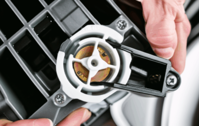
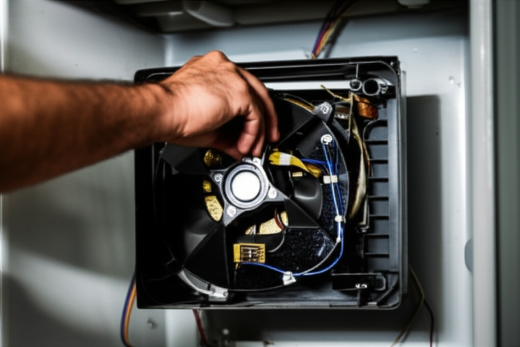
Appliance Case Tie‑In: Why Evaporator Fan Motors Buzz or Run Hot
Let’s connect lamination choices to a familiar product: the evaporator fan motor in a freezer. Many readers search for “Maytag freezer not cooling,” “freezer fan motor buzzing,” or “evaporator fan motor replacement Maytag” because a fan starts squealing or the freezer sits warm while the compressor runs. Engineers behind those motors care about the same lamination fundamentals we have covered.
Here is how laminations show up in the field:
- Noise and vibration
- A noisy evaporator fan motor that makes buzzing, grinding, or squealing noises can point to bad bearings or a damaged fan blade. Laminations also matter. Poor interlaminar insulation or high magnetostriction grades amplify tonal hum at twice line frequency or at PWM harmonics.
- Bonded stacks reduce chatter and radiated noise. Interlocks can rattle if tolerance drifts. When customers hear “Maytag freezer noisy fan,” they hear the sum of bearings, blade balance, PWM strategy, and lamination mechanics.
- Efficiency and temperature
- If the evaporator fan’s core loss runs high, the motor runs hotter for the same airflow. In a tight freezer compartment, every watt matters. Lower loss laminations help prevent “Maytag freezer warm inside” complaints when airflow drops due to thermal throttling or premature winding aging.
- Reliability
- Consistent stack factor and controlled burr height reduce hotspots. That supports long life in a motor that cycles often and deals with frost. Many service complaints say “freezer fan not spinning Maytag” or “evaporator fan motor won’t start Maytag.” Some are electrical or ice‑related. Solid lamination practice keeps the magnetic circuit out of the failure pile.
Engineers and procurement teams working on these motors often compare OEM and aftermarket part performance. OEM Maytag evaporator fan motors will target specific lamination grades and coatings to hit efficiency, acoustic, and cost targets. Aftermarket equivalents may use different laminations or assembly methods. That can change noise or temperature a bit even when the motor fits and runs.
If your team supports field diagnostics or service guides, you see the usual checks:
- Confirm symptoms: no airflow from vents, a compressor running but no cooling, or a freezer clicking then stopping
- Visual checks: fan blade hitting something, ice build‑up around the evaporator cover, or a loose fan blade
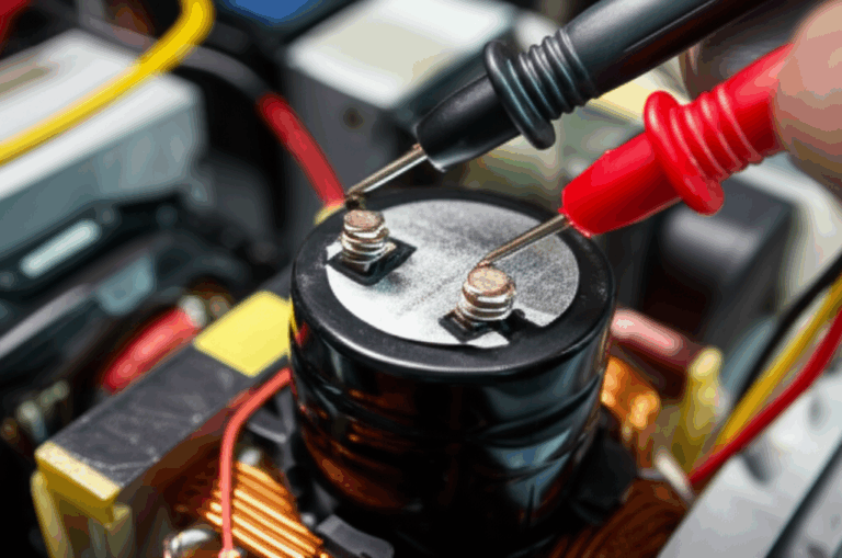
- Electrical checks: continuity and resistance of the motor windings with a multimeter, voltage at the connector, and occasionally a safe brief power test
- System checks: defrost heater and thermostat function, control board outputs, and thermistor accuracy
These checks show why lamination decisions matter. Lower loss and better damping reduce heat and noise at fixed airflow. That buys margin when frost builds on coils or when airflow paths clog. It also reduces field complaints like “Maytag freezer making humming sound” or “evaporator fan motor running slow Maytag.”
If you work across Whirlpool, Amana, KitchenAid, or Kenmore platforms, you already manage shared motor platforms and similar parts. A common lamination strategy lets you scale while tuning acoustics and cost by model.
You do not need to turn this section into a service manual. You only need to see the line from lamination material and assembly choice to real‑world symptoms. It helps align your design, quality, and service teams around the same physics.
Engineering Takeaway and Next Steps
Let’s boil it down to the essentials you can act on.
- Define your duty point first
- Frequency range, peak flux density, efficiency target, temperature rise, and acoustic limits drive everything else.
- Pick material and thickness to match frequency and flux
- Use NOES for most rotating machines. Drop lamination thickness as frequency rises. Move to cobalt alloys only when you must.
- Choose a manufacturing method that fits volume and noise needs
- Stamp for volume. Laser or EDM for prototypes. Bond when noise matters and interlocks when cost and throughput matter.
- Lock down stack factor, burr limits, and insulation class
- Put them on the drawing. Measure them in pilots. Update your FEA to real values.
- Validate with data at your duty point
- Ask for magnetic property curves near your operating frequency and peak B. Measure specific loss in your assembled stacks and compare to flat‑sheet data.
- Partner early with your supplier
- Share acoustic and thermal targets. Align on anneal and bonding cycles. Avoid surprises downstream.
When you are ready to translate design choices into manufacturable stacks, review a focused stator or rotor guide. This overview on stator core lamination covers slot shapes, skew, and bonding at a practical level. Pair it with a look at rotor core lamination if you are tuning bars or magnets. If you want a broad view of how material family, insulation, and stack methods come together across machines, this page on motor core laminations is a good starting point.
If you prefer to step back and level‑set on material families and their magnetic behavior, the high‑level primer on electrical steel laminations can help your team choose a baseline grade before you run a deep FEA pass.
You do not need to chase exotic solutions to hit your goals. You need a clear definition of your duty, a right‑sized material and thickness, and a manufacturing plan that protects edges and insulation. Do that, and you cut loss, tame noise, and simplify procurement.
Action items you can take this week:
- Capture your duty point in one page with frequency, peak B, efficiency, temperature rise, and sound targets
- Shortlist two NOES grades and two thicknesses. Request magnetic curves at your duty point from vendors
- Build a laser‑cut pilot stack. Measure core loss and burr height. Anneal and remeasure to see process impact
- Decide early whether you will bond or interlock. Run a small bake study if you bond
- Review your drawings to add stack factor, interlaminar resistance, burr height, and anneal notes
If you want a quick sanity check on your lamination plan, set up a technical consultation with your supplier’s engineering team. Bring your duty point, early geometry, and noise targets. You will leave with a clearer path and a better quote.
References and Standards for Further Reading
- IEC 60404 series on magnetic materials measurement methods and properties
- ASTM A677 specification for nonoriented electrical steel
- IEEE papers and tutorials on core loss modeling and lamination manufacturing effects
- Vendor datasheets for specific NOES and cobalt‑iron grades with loss vs frequency curves
Final note on language and clarity. If you explain this to a colleague, avoid jargon unless you define it on the spot. Say “eddy currents act like whirlpools that heat the core” rather than “loss is dominated by Je2R at f2.” You will bring more people along for the ride. That pays off when design, manufacturing, and procurement need to row in the same direction.