Motor Laminations Demystified: How to Choose Materials, Thickness, and Processes for Better Motors
Every design engineer faces a stubborn mix of constraints. You need higher efficiency, higher power density, lower noise, and a BOM that makes procurement smile. At the core of that challenge—literally—sit your motor laminations. Material grade, thickness, coating, cut process, and stack assembly all raise or lower the ceiling on what your motor can do. If you’re weighing trade-offs like “0.35 mm vs 0.20 mm” or “laser vs stamping” and wondering how much it really affects loss, torque ripple, or total cost, you’re in the right place.
I’ll walk you through the fundamentals. No hand-waving. Just clear engineering logic tied to practical manufacturing realities. You’ll see why laminations behave the way they do, which options match which applications, and how to specify what matters without overspending. You’ll leave with a checklist you can use with any lamination supplier.
In This Article
- Why Lamination Choice Drives Efficiency, Cost, and Reliability
- Core Losses Explained: Eddy Currents and Hysteresis
- Material Options: CRNGO, CRGO, NOES, GOES, Cobalt, and Amorphous
- Thickness, Coatings, and Insulation: How They Reduce Loss and Improve Stacking
- Cutting and Forming: Stamping, Laser, Wire EDM, and Waterjet
- Stack Assembly: Interlocking, Welding, Bonding, and Riveting
- Tolerances, Burrs, Flatness, and QC: What to Specify and Why
- Application Fit: Induction, BLDC/PM, Traction, Aerospace, High-Frequency Drives
- Cost Drivers and Procurement Playbook
- Common Mistakes and How to Avoid Them
- Engineering Takeaway and Next Steps
Why Lamination Choice Drives Efficiency, Cost, and Reliability
Here’s the problem in plain terms. A motor converts electrical energy into mechanical work through a time-varying magnetic field. That field doesn’t just do useful things. It also creates losses in the core that show up as heat. Hot motors run less efficient and age faster. The lamination stack is your primary lever to cut those losses without eating torque.
You manage that with:
- Material grade and thickness that reduce eddy currents and hysteresis.
- Surface insulation that keeps sheets electrically isolated.
- Cutting and assembly processes that preserve magnetic properties.
- Tolerances and burr control that maintain good air-gap quality and repeatability.
- A stack build that lives through vibration and duty cycles without loosening.
Get those right and your motor runs cooler at the same output. That can push you into a smaller frame or give you headroom for tougher duty cycles. You’ll also make your supply chain happier because the right choices reduce rework and improve yield.
Core Losses Explained: Eddy Currents and Hysteresis
Let’s break the physics down simply.
- Eddy currents: Think of eddy currents like tiny whirlpools in a river. A changing magnetic field induces circulating currents in the steel. Those loops burn energy as heat. Thin, well-insulated laminations chop large loops into small, weak ones. You get lower eddy-current loss at a given frequency and flux density.
- Hysteresis: When you magnetize a material then reverse it, the material doesn’t snap back instantly. It lags and wastes energy each cycle. That lag shows up in the B-H loop. A narrower loop means lower hysteresis loss. Materials with low coercivity (resistance to demagnetization) generally have lower hysteresis loss.
Two practical levers control both:
- Reduce thickness to cut eddy current loops.
- Use higher-grade steel with lower coercivity and refined grain structure to cut hysteresis.
Permeability also matters. Think of permeability as how easily the material “soaks up” magnetic flux lines. Higher initial and maximum permeability reduce magnetizing current for a given flux. That helps efficiency and torque density.
Frequency changes the game. At 50–60 Hz, 0.5 mm or 0.35 mm non-oriented electrical steel (NOES) might be fine. Push switching to a few kilohertz with a PWM drive and eddy-current loss climbs fast. You either go thinner, choose a better grade, or both. In very high-frequency designs you may reach for cobalt-iron or nanocrystalline materials. Those options cost more but unlock performance that standard NOES cannot match.
Material Options: CRNGO, CRGO, NOES, GOES, Cobalt, and Amorphous
Start with the most common families. Then match them to duty cycle, frequency, temperature, and cost targets.
- Cold-rolled non-grain-oriented (CRNGO or NOES)
- Use: General-purpose motors, induction motors, BLDC stators, traction motors.
- Behavior: Nearly isotropic magnetic properties in the plane of the sheet. Stable performance across directions. Available in many grades and thicknesses.
- Pros: Broad availability, reasonable cost, good balance of loss and permeability.
- Cons: Not as low-loss as grain-oriented along its preferred direction. Not as high performance as cobalt or amorphous at very high frequency.
- Cold-rolled grain-oriented (CRGO or GOES)
- Use: Transformers and devices that run near one flux direction.
- Behavior: Extremely low loss along the rolling direction. Much higher loss transverse to it.
- Pros: Outstanding low-frequency core-loss in the rolling direction.
- Cons: Anisotropy complicates motor cores where flux rotates. You rarely use GOES for rotating machines.
- High-grade NOES (ultra-low-loss variants)
- Use: Premium efficiency motors, EV traction motors, aerospace actuators.
- Behavior: Lower core loss at high flux density and frequency. Tight thickness tolerance.
- Pros: Big impact on both eddy and hysteresis losses at 50–400 Hz and under PWM.
- Cons: Higher cost and sometimes tighter supply.
- Cobalt-iron alloys (e.g., ~49% Co)
- Use: High power density machines, high-frequency applications, aerospace, magnetic bearings.
- Behavior: Higher saturation flux density than NOES. Lower core loss at elevated frequency. Excellent mechanical strength at temperature.
- Pros: Enables smaller, lighter machines with higher peak flux. Good at elevated temperature.
- Cons: Much higher cost. Harder to cut. Tooling wears faster.
- Amorphous and nanocrystalline alloys
- Use: High-frequency transformers and specialized motors. Prototypes or niche.
- Behavior: Very low eddy current loss due to thin ribbons and disordered structure.
- Pros: Lowest possible core loss at high frequency.
- Cons: Difficult to stamp into complex rotor/stator geometries. More common in transformer cores than rotating machines.
If you need a primer on base materials and product forms, review the fundamentals of electrical steel laminations to see thickness ranges, grades, and insulation systems typically available.
What grade naming means in practice
You’ll see codes that imply thickness and loss. Different regions use different nomenclature. Many suppliers will quote loss at a given flux density and frequency per IEC 60404 methods. Ask for:
- Sheet thickness tolerance.
- Guaranteed core loss at specified B and Hz.
- Permeability curves.
- Coatings: type, class, and max temperature.
Don’t chase the lowest loss number without context. Verify at your operating flux density and frequency. Loss curves bend with both.
Thickness, Coatings, and Insulation: How They Reduce Loss and Improve Stacking
Thickness is your blunt instrument against eddy currents. Halve thickness and you roughly quarter eddy current loss in the classical approximation. That rule of thumb holds best in the lower kHz range and for similar coatings. The real world brings coatings, burrs, and frequency-dependent effects into the mix.
Common thickness choices:
- 0.50 mm: Traditional for 50/60 Hz machines. Lower cost. Higher loss.
- 0.35 mm: A sweet spot for general-purpose motors. Better loss with manageable cost.
- 0.27–0.30 mm: Premium industrial motors and traction. Good compromise for PWM drives.
- 0.20–0.23 mm: High-frequency, high-performance. Cost rises. Handling gets trickier.
Remember density and slot fill. Thinner laminations increase sheet count for the same stack height. That can affect stacking time, deformation risk, and insulation volume fraction.
Insulation coatings and interlaminar resistance
Each sheet carries an inorganic or organic coating that provides electrical isolation between laminations. That coating bumps interlaminar resistance up which clamps eddy loops. Coatings also prevent welding of sheets during stamping and reduce sticking.
Key points to specify:
- Coating class and thickness. Thin coats save space. Thick coats improve isolation.
- Temperature rating. Confirm it matches your worst-case thermal rise with margin.
- Dielectric breakdown voltage or interlaminar resistance test method.
- Compatibility with your bonding or welding process.
Stack factor matters. It’s the ratio of metallic stack height to the total stack height. High stack factor means less coating thickness and burr volume. You want a high stack factor but not at the expense of eddy current isolation or lamination shorting.
Cutting and Forming: Stamping, Laser, Wire EDM, and Waterjet
Your cutting method changes magnetic performance, dimensional accuracy, burrs, and cost. Choose based on volume, part complexity, tolerance, and the magnetic sensitivity of your application.
- Progressive die stamping
- Best for: High volume. Simple to moderate complexity. Tight repeatability.
- Pros: Lowest cost per piece at volume. Good dimensional control. Compatible with interlocks.
- Cons: Tooling cost and lead time. Mechanical stress and burrs at the edge. Tool wear with harder alloys.
- Fine blanking or precision stamping
- Best for: Tighter edge quality and lower burr heights while keeping high throughput.
- Pros: Better edge integrity than standard stamping.
- Cons: Higher tooling and per-part cost than standard progressive dies.
- Laser cutting
- Best for: Prototyping, small runs, complex geometries, frequent design changes.
- Pros: No hard tooling. Fast iterations. Excellent feature flexibility.
- Cons: Heat-affected zone (HAZ) can raise local loss if you don’t control parameters. Edge recast and microstructure change can require a post-process stress relief.
- Wire EDM
- Best for: Ultra-precise prototypes and critical features. Low burr. Minimal HAZ compared to laser.
- Pros: Superb edge quality. Tight tolerances.
- Cons: Slow and expensive for volume production.
- Waterjet
- Best for: Some prototypes where HAZ must be avoided and edge quality demands sit between laser and EDM.
- Pros: No thermal damage.
- Cons: Edge roughness and taper can be higher. Slower than laser. Not ideal for mass production.
If your motor runs at higher frequency with a thin lamination and tight loss budget, laser settings and post-processes matter. Consider a low-distortion cut strategy, nitrogen assist gas, or a light stress relief anneal if material and coating allow it. Protect the insulation. Verify that any anneal stays below coating limits.
Stack Assembly: Interlocking, Welding, Bonding, and Riveting
How you build the stack matters. It changes stiffness, noise, long-term stability, and magnetic performance at the edges.
- Interlocking
- Process: Tabs and notches that snap sheets together. Think LEGO bricks for steel.
- Pros: No added materials. Fast assembly for stamped parts. Good for high volume.
- Cons: Localized deformation around interlocks. Slightly lower stack factor in those regions. May add small torque ripple if placed poorly.
- Welding (tig, laser, spot)
- Pros: Strong mechanical joint. Good for rotors or robust stators. Simple fixture setups.
- Cons: Local heat can degrade magnetic properties near welds. Coatings burn off locally. Clean up spatter and manage distortion.
- Bonding (varnish or adhesive)
- Pros: Uniform bonds. Lower noise. Very good dynamic stability. Excellent for high-speed rotors and quiet stators.
- Cons: Process control matters. Cure cycles add time. Adhesive selection must match operating temperature and environment.
- Riveting or cleating
- Pros: Simple. No heat-affected zones. Reliable for certain geometries.
- Cons: Permanent holes reduce cross-section and add stress concentration.
For high-speed PM rotors or machines with strict NVH targets, bonded stacks shine. For rugged industrial machines where simplicity and cost win, interlocks or welds may be the better path. You can blend methods. For example, interlock for speed and add a few welds or rivets for extra stiffness.
Tolerances, Burrs, Flatness, and QC: What to Specify and Why
Small geometric errors add up in a motor. A few simple specs improve performance and yield.
- Burr height: Lower burrs reduce interlam shorting and improve stack factor. Typical targets fall below 10–20 µm for high-performance stacks. Confirm how your supplier measures burr height. Edge rounding options can help.
- Flatness and twist: Critical for low-noise stators where tight air gaps and uniform stack compression matter. Specify flatness per part and at the stack level.
- Dimensional tolerances: Focus on tooth width, slot width, and outer/inner diameter roundness. Tighter tolerances increase tooling cost. Place tight control where it changes performance.
- Grain direction marking (if any): For GOES parts used in special subassemblies, mark rolling direction clearly.
- Cleanliness: Oil, dust, or bond-line contamination cause problems later. Specify cleanliness class if you plan to bond.
- Magnetic acceptance tests: For critical applications, request Epstein-frame or single-sheet test data per IEC 60404 or equivalent. You can also request ring-core tests for representative stacks.
- Stress relief: If you laser or form parts that stress the steel, a low-temperature stress relief can recover magnetic performance. Confirm coating limits first.
- Stack compression: Define bolt torque or press tonnage and target stack height under load. Good compression improves damping and reduces vibration. Confirm you don’t crush coating beyond its design.
Dimensional control improves with experienced tooling plus a process tuned to your material choice. That is where good lamination partners pay off.
Application Fit: Induction, BLDC/PM, Traction, Aerospace, High-Frequency Drives
Different machines push different levers. Match the approach to your duty cycle and constraints.
Induction motors (50/60 Hz industrial)
- Material: Mid to high-grade NOES in 0.50–0.35 mm.
- Focus: Low hysteresis at the selected flux density and frequency. Stamping with tight burr control. Interlocking or welding works well.
- Why: You run at relatively low frequency which reduces eddy loss sensitivity to thickness. Efficiency codes like IE3 and IE4 can justify higher-grade NOES.
BLDC/PM motors (with PWM drives)
- Material: Thin NOES 0.35–0.20 mm for stators. Consider bonded stacks for noise control. PM rotor back-iron can be thicker but depends on speed and flux.
- Focus: Eddy current loss in teeth under PWM. Low torque ripple through tight tolerances. Laser or stamping depending on volume.
- Note: For compact designs with high slot fill, you may want advanced bonding to reduce buzz. For a quick look at common configurations, review a practical bldc stator core example and the features that matter at higher electrical frequencies.
EV traction motors
- Material: High-grade thin NOES (0.27–0.20 mm). In select cases cobalt-iron in critical subregions.
- Focus: High speed and high frequency under heavy load. NVH and thermal limits under fast transients. Bonded stacks favored for stability and noise.
- Why: Aggressive drive cycles and switching frequencies punish eddy losses and looseness. The premium material cost often pays for itself in efficiency and power density.
Aerospace actuators and high-frequency specialty motors
- Material: Cobalt-iron alloys for high saturation and temperature capability. Thin gauges.
- Focus: Weight savings, thermal resilience, minimal core loss at elevated frequency. Precise cutting such as EDM for critical geometries.
- Why: Every gram and watt matters. You use the sharpest tools in the drawer.
Transformers and static magnetic components
- Material: CRGO for low-frequency transformers. Amorphous or nanocrystalline for high-frequency power electronics.
- Focus: Magnetic orientation and low core loss in one direction. Laminated or tape-wound cores as needed.
Stator vs Rotor: What Changes and Why
Stator and rotor design choices diverge because their roles and stresses differ.
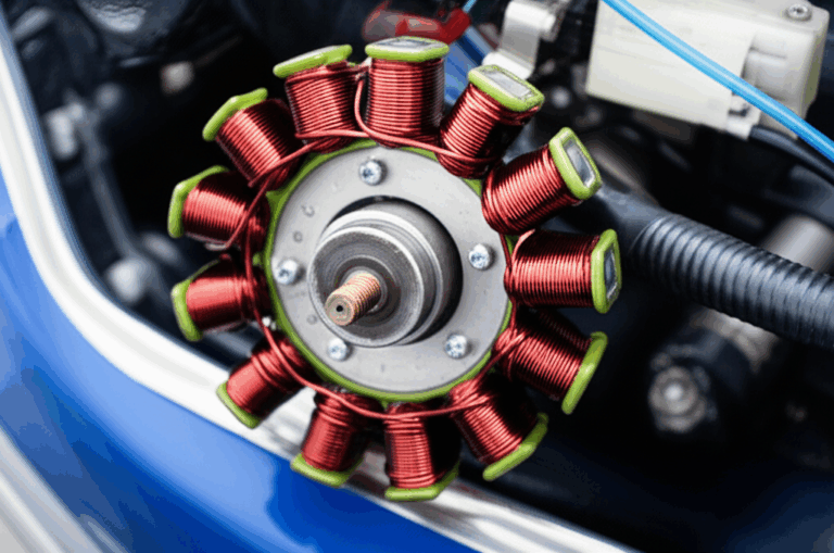
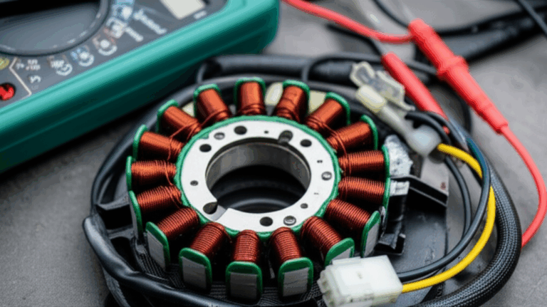
- Stator
- Priorities: Tooth-tip geometry for cogging control. Slot shape for copper fill and thermal path. Noise and vibration control through bonding or compression.
- Process: Stamping for volume. Laser or EDM for complex prototypes. Bonding improves NVH.
- Helpful reference: See how a well-built stator core lamination stack supports tight air gaps and repeatable slot geometry.
- Rotor
- Priorities: Mechanical integrity at speed. Balance. Heat rejection from the rotor. Flux path under magnets or squirrel cage bars.
- Process: Bonding or welding for high-speed rotors. Fine control of holes or magnet pockets. Pay close attention to retention features and stress concentrations.
- Helpful reference: A robust rotor core lamination scheme protects mechanical margins and maintains magnetic performance.
If you need a single view that ties both sides together, skim the basics of complete motor core laminations to see how the stator and rotor interact through the air gap.
Cost Drivers and Procurement Playbook
You can manage cost without kneecapping performance. Focus on the levers that move total cost of ownership.
- Material grade and thickness
- Thinner and higher-grade steels cost more. They can shrink the frame or raise efficiency enough to offset that premium. Measure the payback in energy saved and system downsizing.
- Tooling
- Progressive dies cost upfront but crush per-part cost at volume. If you’re early in design or expect changes, laser or EDM avoids sunk cost until you lock geometry.
- Yield and scrap
- Nesting strategy and strip width choice drive scrap rates. Involve the supplier early. A small geometry tweak can save a lot of material across a long production run.
- Secondary operations
- Bonding, annealing, deburring, or edge treatments add cost. Use them where they solve a real problem that you can quantify.
- Quality requirements
- Don’t blanket tight tolerances across everything. Put cost where it moves performance. Tooth geometry and air-gap-critical diameters matter most.
- Logistics and packaging
- Flatness can degrade in transit. Use packaging and stacking fixtures that protect parts. That small cost saves a fortune in rework.
The best procurement decisions combine a spec that targets what truly matters with a supplier who can hit it repeatedly. You want a consistent stack factor, repeatable burr control, and reliable coating performance.
Common Mistakes and How to Avoid Them
- Picking a grade by one number
- Don’t choose a steel using a single core-loss value at one test point. Match the curve to your actual operating B and frequency.
- Ignoring cutting-induced damage
- Laser parameters and stamping stress affect local loss. Ask about HAZ control, die maintenance, and stress relief options.
- Over-tight tolerances where they don’t pay off
- Tolerances cost money to hold. Use tight control on teeth, slots, and critical diameters. Relax non-critical features to save money.
- Forgetting stack factor in designs with thin laminations
- Thin sheets add more coating volume fraction. That changes the magnetic cross-section. Validate with your supplier’s stack factor data.
- Under-specifying insulation
- The wrong coating fails in a hot motor. It also fights your bonding adhesive. Align coating class and adhesive chemistry.
- Treating stator and rotor the same
- Different stress states, different risks. Bonded stators can cut noise. Bonded rotors can improve high-speed integrity.
Practical Design Rules of Thumb
These won’t replace analysis. They keep you out of trouble during early sizing.
- Higher frequency demands thinner steel. You can keep loss under control by going from 0.35 mm to 0.27 mm or 0.20 mm as PWM frequency rises.
- Keep flux density conservative where core loss climbs fast. If you push into higher B for torque density, verify thermal headroom.
- For high-speed rotors, avoid sharp corners in magnet pockets or bridges. Smooth transitions spread stress.
- Place interlocks away from tooth tips if you want to minimize torque ripple effects.
- If you need a quiet stator, bonding beats interlocks in most cases.
- Ask for burr height and stack factor data in every quote. Those numbers predict real-world performance more than a glossy data sheet.
Validation and Testing: How to De-Risk Before You Cut Steel
- Material coupon tests
- Request core-loss and permeability data per IEC 60404 or local standards at your B and frequency.
- Single-tooth or ring-core tests
- Validate local loss under PWM. Map how tooth tips behave at switching ripple frequencies.
- Prototype stack builds
- Try the actual manufacturing process. Laser for rev A then stamp a short run with pilot tooling. Compare loss and NVH.
- Thermal and NVH validation
- Instrument the prototype for temperature and vibration under worst-case duty cycle. Verify that stack assembly meets your targets.
- Quality gates
- Incoming inspection for thickness tolerance, coating quality, and burr height. SPC on critical dimensions.
Where Laminations Meet the Rest of the Motor
Design lives at the interfaces.
- Winding strategy affects slot fill and tooth-tip saturation. More copper can be good until it overheats the teeth.
- The housing and cooling plan set your thermal ceiling. Don’t design a low-loss core then starve it of cooling air or coolant.
- The inverter sets PWM frequency and harmonic content. Coordinate with power electronics to avoid loss spikes at unfortunate switching frequencies.
- The magnet grade and geometry set rotor back-iron depth. Saturation in back-iron eats torque margin.
Keep the conversation going across disciplines. Small changes in one domain ripple through the others.
A Short, Real-World Example
You want to redesign a 5 kW BLDC motor to hit a 2% efficiency gain without adding cost to the BOM. You run a 10 kHz switching frequency with ripple that raises teeth loss.
- Move stator lamination thickness from 0.35 mm to 0.27 mm in a slightly higher NOES grade.
- Change stack assembly from interlocked to bonded to reduce buzz and improve tooth-tip stiffness.
- Ask for a laser-prototyped stack with low HAZ parameters and a test anneal within coating limits. Validate loss and NVH.
- If the anneal gains you nothing due to coating constraint, make sure stamping is the plan for production with a fresh die set and aggressive burr control.
- The result: Lower core loss in teeth where ripple hits hardest. Lower audible noise. Material cost increases modestly but you save energy across the duty cycle which often repays the change quickly.
Procurement Checklist You Can Use Today
- Material
- Grade, thickness, and guaranteed core loss at your B and frequency.
- Permeability curve. Coercivity data.
- Coating type, thickness, dielectric strength, temperature rating.
- Manufacturing
- Cutting method, expected burr height, edge quality strategy, HAZ control if laser.
- Tooling life plan and maintenance schedule if stamping.
- Stack assembly
- Method (interlock, weld, bond, rivet).
- Stack factor target. Compression method and torque.
- QA/QC
- Dimensional tolerances for teeth, slots, OD/ID. Flatness and twist.
- Magnetic acceptance tests per IEC 60404 or equivalent.
- Cleanliness and packaging requirements.
- Logistics
- Lead times, batch sizes, and buffer strategy.
- Traceability for material heats and coatings.
“Which Option Fits My Application?” Quick Guide
- Prototype or low volume with frequent design changes
- Laser or EDM cut. Bonding or simple rivets. Thin NOES or specialty alloy as needed.
- High-volume industrial motor
- Progressive die stamping. Interlocks or welds. 0.50–0.35 mm NOES, grade chosen for IE efficiency target.
- EV traction motor
- Thin high-grade NOES at 0.27–0.20 mm. Bonded stacks. Tight burr and flatness control.
- Aerospace or high-frequency specialty
- Cobalt-iron or advanced NOES. EDM for critical parts. Bonded stacks. Rigorous QC and acceptance testing.
If you want to see how these pieces come together in a typical lamination program, review the capabilities and scope of complete motor core laminations including options for stack build and QA.
Your Questions on Stators and Rotors, Answered Fast
- Do thinner laminations always beat thicker ones
- Not always. They cut eddy loss but add cost and complexity. The right choice depends on frequency and your efficiency target.
- Should I use grain-oriented steel in motors
- Rarely. Motors have rotating flux. GOES shines in one direction which doesn’t map well to a stator tooth with rotating fields.
- Is laser cutting safe for production
- It can be, with the right parameters. Many teams prototype with laser then switch to stamping for volume due to cost and HAZ control.
- How do I keep stacks quiet
- Bonding helps. So does careful slot/tooth geometry and a tight air gap. A rigid housing and good compression finish the job.
- What about BLDC stators specifically
- They often benefit from thinner NOES and tight tooth-tip control. It’s worth looking at a dedicated bldc stator core configuration that suits your winding and magnet layout.
References and Standards You Should Know
- IEC 60404 series: Methods for measuring magnetic properties of electrical steels.
- ASTM and ISO standards that cover electrical steel specifications and test practices for thickness, coating, and magnetic loss.
- IEEE literature on motor efficiency testing and loss breakdown in rotating machines.
Ask suppliers to state which methods they used when they quote loss numbers. Apples-to-apples comparison beats marketing gloss.
Engineering Takeaway
- Core loss comes from eddy currents and hysteresis. Thin sheets and better steel grades cut both.
- Material choice is application driven. NOES fits most motors. Cobalt-iron and amorphous fill high-frequency or high-density niches.
- Cutting and stacking change magnetic behavior. Control HAZ, burrs, and compression.
- The best stack assembly method depends on NVH, speed, and duty cycle. Bonding often wins for quiet or high-speed machines.
- Specify what moves performance: tooth geometry, air-gap-critical diameters, burr height, stack factor, and coating class.
- Validate with realistic tests at your B and frequency. Prototype with the intended production process whenever possible.
If you want a concise refresher by component, see:
- Stator fundamentals and build options: stator core lamination
- Rotor integrity and geometry control: rotor core lamination
- Material families and availability: electrical steel laminations
- Full-stack considerations and supplier capabilities: motor core laminations
- BLDC-specific stator considerations: bldc stator core
Next Steps: Your Action Plan
- Clarify your operating envelope: flux density, base frequency, switching strategy, and thermal limits.
- Choose a target lamination thickness based on frequency, then pick two realistic material grades to compare.
- Select a cutting method that matches your volume and tolerance needs. Prototype with the intended process if you can.
- Decide on a stack assembly approach that meets NVH and mechanical requirements.
- Write a spec that calls out coating class, burr height, stack factor, and magnetic acceptance tests. Keep tolerances tight where they matter most.
- Run a quick loss and thermal analysis with both material options. Pick the one with the best system-level payback, not just the lowest per-part price.
- Engage your lamination partner early. Share duty cycle, switching details, and performance targets. Better inputs yield better parts.
If you’d like a second set of eyes on your spec or a quick DFM review, reach out for a technical consultation. A short call can save weeks on the back end and help you hit your efficiency and cost targets with confidence.

