Motor Laminations 101: The Practical Guide to Materials, Manufacturing, and Decisions That Drive Efficient Motors
Every design engineer faces the same brutal tradeoff. You want higher motor efficiency yet you have a budget and a deadline. You need torque density and thermal headroom yet you also need a manufacturable stack with acceptable scrap rates and a clean PPAP. If you’ve ever stared at a drawing wondering whether 0.27 mm laminations and a Class C-5 coating make sense for your frequency envelope you’re in the right place.
This article answers the question that sits under many others: how do lamination material, thickness, coating, and manufacturing choices shape motor performance and cost. We’ll break the physics down. We’ll compare real options without hype. Then we’ll give you a clear checklist so you can spec smart and talk with suppliers like an expert.
In short we’ll follow the Problem – Explain – Guide – Empower model. You’ll leave with a path you can use today.
In This Article
- Why Lamination Choice Is Critical
- Core Loss Fundamentals: Eddy Currents and Hysteresis
- Lamination Materials Guide: Silicon Steels, Co-Fe, and Emerging Alloys
- Manufacturing and Assembly Processes That Matter
- Matching Solutions to Applications
- Quality, Inspection, and Clean Handling in Production and Service
- Procurement and Cost: What to Specify and Why
- Do’s and Don’ts for Reliable Motor Core Design
- Your Engineering Takeaway
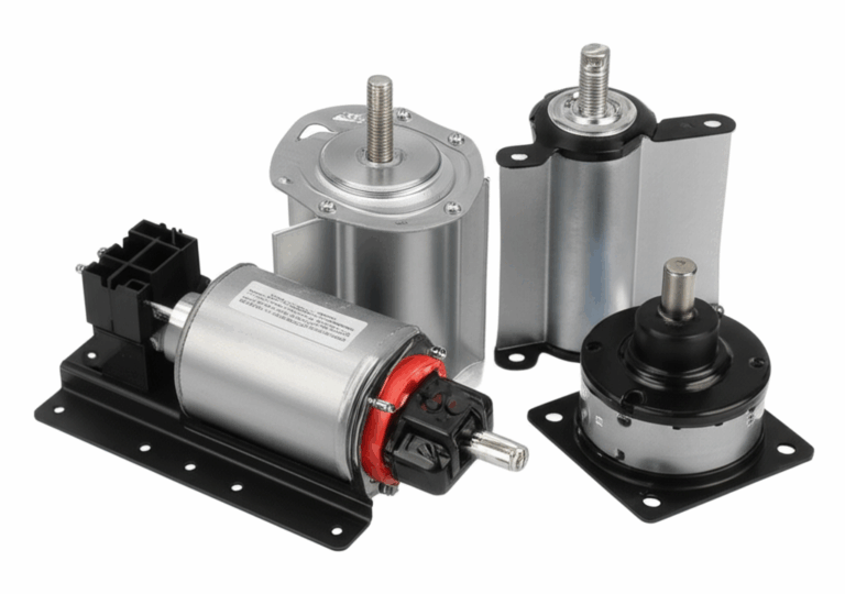
Why Lamination Choice Is Critical
Laminations sit at the heart of your stator and rotor. They steer magnetic flux. They set the ceiling for core losses. They influence thermal behavior and acoustic noise. They also dictate tool design, yield, and lead time. You don’t fix a poor lamination choice downstream because copper fill, magnets, and control algorithms can only save so much.
The most direct levers you control are:
- Material family and grade (non‑oriented silicon steel vs cobalt‑iron vs others)
- Thickness (for your frequency and flux density range)
- Insulation coating class and interlaminar resistance
- Manufacturing route (progressive stamping vs laser cutting vs EDM)
- Stack method (interlock, welding, bonding, riveting, segmenting, skew)
The quality of your motor core laminations defines the loss baseline your design must live with. Start there and you’ll make better choices everywhere else.
Core Loss Fundamentals: Eddy Currents and Hysteresis
Let’s keep the physics intuitive. Two loss mechanisms dominate laminated cores.
- Eddy current loss: Picture small whirlpools in a river. A changing magnetic field induces circulating currents in the steel that form those whirlpools. They create heat and waste energy. Thinner laminations with good insulation break large whirlpools into many tiny ones which slashes loss.
- Hysteresis loss: Think of bending a paperclip back and forth. The metal resists that reversal. Magnetic materials behave similarly when their magnetization flips each cycle. That resistance is hysteresis. Materials with lower coercivity (resistance to demagnetizing) bend more easily and waste less energy.
Both losses grow with frequency and flux density. That’s why high‑speed machines care so much about thickness and alloy choice.
Lamination Thickness vs Frequency
You can treat thickness as your eddy‑current knob. As frequency rises you reduce thickness to keep eddy currents in check.
- 50/60 Hz industrial motors commonly use 0.50 mm to 0.35 mm non‑oriented electrical steel
- 200–400 Hz servo and traction designs often step to 0.35 mm to 0.27 mm
- High‑speed BLDC and e‑compressor rotors can justify 0.20 mm and thinner
Yes thinner laminations add cost and handling complexity. They also increase stack height for the same magnetic path which can affect slot fill. You balance those effects against loss savings and thermal margin.
Flux Density and the B‑H Curve
Magnetic flux density (B) and magnetic field strength (H) relate through the material’s B‑H curve. Magnetic permeability describes how easily the steel “soaks up” flux like a sponge absorbs water. At low B the material behaves linearly. At higher B it starts to saturate which skyrockets loss and distorts waveforms. If your design runs near the knee of the B‑H curve you’ll pay for it in heat and acoustic noise.
Insulation Coatings and Interlaminar Resistance
Insulating coatings keep lamination surfaces electrically separate. High interlaminar resistance limits eddy currents across sheets. You’ll see classifications by type and thickness along with bake and bond properties. Standards like ASTM A976 classify coatings by function and test methods. You choose coatings by:
- Stamping lubricity and tool life
- Bonding behavior if using backlack
- Maximum bake temperature and insulation stability
- Corrosion resistance and storage stability
Stacking Factor
Stacking factor tells you how much of your stack height is actual steel vs coating and trapped air. You’ll use this factor in magnetic path calculations and mass estimates. Thinner laminations with higher coating thickness reduce stacking factor which slightly increases the magnetic path length. You need that number to predict performance correctly.
Lamination Materials Guide: Silicon Steels, Co‑Fe, and Emerging Alloys
You have more than one knob for reducing core loss. Material selection moves both hysteresis and eddy components.
Non‑Oriented Silicon Steel (CRNGO)
This is the workhorse for rotating machines. Silicon additions (usually 2–3%) reduce core loss and increase resistivity which helps eddy currents. “Non‑oriented” means magnetic properties are fairly uniform in all directions which suits stator teeth and yokes. Grades historically appear as “M‑numbers” in North America and as EN or JIS grades elsewhere. Better grades have lower loss at a given thickness.
Use cases:
- General purpose induction and PM motors
- Servo motors up to a few hundred hertz
- Cost sensitive designs that still need solid efficiency
Pros:
- Broad availability and predictable performance
- Reasonable cost and good stampability
- Compatible with a range of coating classes
Cons:
- Not the lowest loss at very high frequency
- Limited saturation improvement vs specialty alloys
If you want a refresher on the category see the overview of electrical steel laminations and the basics of silicon steel laminations.
Grain‑Oriented Silicon Steel (CRGO)
Grain‑oriented steel aligns grains during production so it has superior magnetic properties in one direction. Transformers love it because flux flows along the rolling direction. Rotating machinery needs good performance in many directions so CRGO rarely fits stators or rotors. You might use oriented materials for specialized axial‑flux parts or static magnetic circuits. Most traction and industrial motors stick with non‑oriented steels.
Cobalt‑Iron Alloys (Co‑Fe)
Add cobalt and you lift saturation flux density. Co‑Fe alloys can run higher B which supports high power density machines. They also show lower core loss at certain frequency ranges. The tradeoffs are stark. Material price rises and stamping gets harder. You will also revisit coating and bonding because these alloys like higher temperature processing.
Use cases:
- Aerospace and eVTOL actuators
- High‑speed compressors and turbo machines
- Specialty defense systems
Pros:
- Higher saturation supports compact designs
- Lower loss at elevated frequency and flux density
Cons:
- High raw material cost
- Tighter process control and tooling wear concerns
Amorphous and Nanocrystalline Ribbons
These materials shine in transformers due to ultra‑low loss. Rotating machines are a tougher fit because ribbon processing and mechanical properties complicate stack construction. Research continues on segmented stators using ribbon‑based cores for very high frequency drives. If you chase extreme efficiency in niche power ranges it’s a conversation to have with your materials team and suppliers.
Nickel‑Iron Alloys
High‑nickel materials offer very high permeability and low coercivity. Think sensor heads and precision magnetic circuits. They generally can’t take high flux density like Co‑Fe and they bring substantial cost. For motors they see limited use.
Bottom line: start with non‑oriented silicon steel for most rotating machines then justify more exotic alloys only if your frequency and power density demand it.
Manufacturing and Assembly Processes That Matter
How you cut and stack laminations changes actual losses and yield. The physics doesn’t care that you hit the drawing if you damaged the edges with heat or burrs. Let’s compare.
Stamping vs Laser vs EDM
- Progressive die stamping: The production workhorse. High volume. Low cost per piece once tooled. Good edge quality when the die is sharp and clearances are tuned. Burr control is essential since burrs create shorting paths that spike eddy currents.
- Laser cutting: Perfect for prototypes and complex low volume shapes. You get great dimensional flexibility. The heat‑affected zone (HAZ) can increase loss near cut edges especially on thinner gauges. You can mitigate with cutting parameters and post‑processing but you should validate with core loss tests.
- Wire EDM: Very clean edges with minimal HAZ at higher cost and lower throughput. Use it for precision prototypes or special alloys that dislike laser heat.
- Waterjet: Avoid for thin laminations because water and grit are hard on insulation and you risk delamination. It’s workable for thick plates or fixtures not for production lamination sets.
You normally stamp once you lock geometry and volumes rise. You laser or EDM during development when you need speed and frequent design turns.
Burr Control and Deburring
Aim for burr height below your insulation thickness or as specified in your drawing. Burrs that bridge coatings create electrical shorts between layers which torpedo your interlaminar resistance. You can specify burr direction and location so shorts don’t appear at critical flux paths. Light brushing or tumble processes help though over‑processing can reduce stacking factor or damage coatings.
Post‑Anneal
Cutting introduces mechanical stress that raises hysteresis losses. A stress‑relief anneal can bring properties closer to mill spec. You must align anneal temperature with coating class so you don’t degrade insulation. Some coat systems are designed to be annealed. Others are not. Confirm with the steel data sheet.
Insulation Coatings and Backlack
Coatings do three jobs:
- Provide electrical insulation between laminations
- Offer lubricity for stamping and corrosion protection in storage
- Enable bonding when you choose backlack systems
Backlack (bondable) coatings activate under heat and pressure so your stack bonds without welding or rivets. This reduces vibration, improves rigidity, and keeps interlaminar resistance high. Standards such as ASTM A976 help you specify coating class. Your supplier should provide interlaminar resistance test results to verify.
Stack Assembly: Interlock, Welding, Bonding, Riveting
- Interlock: Tabs and lances grip between sheets like LEGO bricks. Fast and efficient. Minimal impact on magnetic properties when designed well. You may see small local disturbances where interlocks compress.
- Welding: Strong and proven though heat can change local microstructure and insulation. Use low heat input techniques and keep welds away from high flux regions where possible.
- Bonding: Activated coatings or separate adhesive layers create rigid, quiet stacks without thermal damage. You trade off process time and bake cycles.
- Riveting or staking: Mechanical methods that suit certain geometries and sizes. They add mass and local stress points but avoid heat.
For skewed stacks you’ll decide whether to skew the stampings or to step‑skew the full stack with indexed segments. Both methods work with the right tooling strategy.
Stator vs Rotor Nuances
- Stators value slot geometry and tooth tip integrity since those drive slot fill and acoustic behavior. Stamping alignment and burr control inside slot mouths matter.
- Rotors can bring segmenting for IPM or reluctance paths. Surface PM rotors care about slotting harmonics and balance. Skew details change torque ripple and noise.
If you need a quick primer on lamination groups see stator core lamination and rotor core lamination.
Matching Solutions to Applications
One size never fits all. Match lamination choices to your frequency, flux density, and business constraints.
50/60 Hz Industrial Motors
- Material: Non‑oriented silicon steel in standard grades
- Thickness: 0.50–0.35 mm
- Coating: Standard insulation optimized for stamping
- Process: Progressive die stamping with interlock or welding
- Why it works: Frequency is low so eddy currents stay manageable with moderate thickness. The cost curve favors stampings and robust coatings.
200–400 Hz Servo and Robotics
- Material: Higher grade non‑oriented silicon steel
- Thickness: 0.35–0.27 mm
- Coating: Better insulation and possibly backlack for low vibration
- Process: Stamping for production with laser for prototyping
- Notes: Validate loss at your actual PWM ripple spectrum not just the fundamental. Skew strategy helps with torque ripple and audible noise.
High‑Speed Compressors, E‑Turbos, and Traction Accessories
- Material: Premium NOES or cobalt‑iron depending on flux target
- Thickness: 0.27–0.20 mm or thinner
- Coating: High temperature systems compatible with any post‑anneal
- Process: Tight burr control and careful HAZ management if laser cutting
- Notes: Your thermal model needs realistic core loss data at high B and high frequency. Don’t extrapolate from 50/60 Hz tables without lab validation.
Aerospace and Defense High Power Density
- Material: Cobalt‑iron alloys
- Thickness: As thin as handling allows for frequency range
- Coating: High temp and bondable for rigid stacks
- Process: Laser or EDM in development then precision stamping
- Notes: You pay for performance. Verify everything with standardized tests. Document measurement methods per IEC 60404 where practical.
Transformers and Static Magnetic Circuits
- Material: Grain‑oriented silicon steel or amorphous ribbon
- Relevance: Useful as a contrast case. Rotating machines want non‑oriented properties which is why you rarely pick CRGO for stators.
Prototypes vs Production
- Prototyping reality: Laser cutting lets you iterate fast and explore slot shapes and skew. You accept slightly higher core loss during early tests.
- Production reality: Stamping delivers the economics once geometry is stable. You invest in progressive dies and qualification runs. You also refine coating class to hit both lamination performance and throughput.
If your project lives in the BLDC world you may also want a closer look at how BLDC skew, slot count, and lamination thickness tie together in a bldc stator core design.
Quality, Inspection, and Clean Handling in Production and Service
Lamination stacks are not delicate art yet they do demand clean habits. Dirt and oil look harmless then they creep into your losses or your winding reliability. A few practical practices keep you out of trouble.
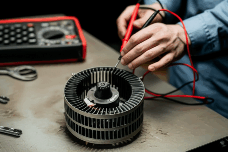
Incoming Material and Dimensional Checks
- Verify thickness, flatness, and coating classification against the mill cert
- Measure interlaminar resistance on representative samples
- Track stacking factor on trial stacks so your models stay honest
- Inspect burr height and direction around slot mouths and outside diameters
Standards like IEC 60404 provide methods for measuring magnetic properties. ASTM A677 covers non‑oriented electrical steel and ASTM A976 classifies coatings. Your supplier should reference equivalent regional standards when applicable.
Clean Manufacturing and Assembly
- Keep cutting and stacking areas clean to avoid grit and dust inclusion
- Use gloves to prevent oils from contaminating coatings
- Store stacks in dry packaging to prevent corrosion
- Avoid over‑clamping during assembly which can crush coatings and reduce interlaminar resistance
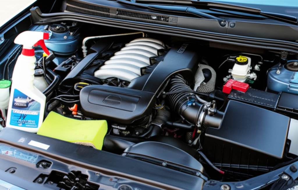
Electric Motor Cleaning in Service
Field maintenance sometimes calls for “cleaning the motor” after contamination or during overhaul. Laminations don’t like conductive grime or corrosion. They also don’t like aggressive washing that strips coatings. If you handle motors in the field consider these safe practices.
- Dry cleaning first: Remove loose contamination with vacuum and filtered compressed air. This addresses dust removal on the motor core and windings without introducing moisture.
- Degreasing without water: For grease removal use non‑conductive, non‑chlorinated solvents compatible with insulation systems. Apply by spray bottle or wipe then capture run‑off. Don’t soak stacks.
- Ultrasonic motor cleaning: You can use ultrasonic baths for disassembled metal parts such as rotor laminations if coatings allow it and if you dry promptly. Validate with your supplier because cavitation can damage thin coatings.
- Dry ice cleaning: Dry ice blasting removes dirt and oil without residue. It’s popular for industrial motor cleaning since it avoids water. Shield bearings and electronics. Keep standoff distances conservative.
- Low‑pressure rinse only when required: If you must rinse use minimal water and keep sensitive components covered. Never use a pressure washer on assembled motors. Water under pressure can force moisture into laminations and windings which invites corrosion and shorts.
- Thorough drying: Use heated air or bake the assembly per insulation system limits. Any retained moisture undermines corrosion prevention and can lower interlaminar resistance at the edges.
- Post‑clean inspection: Look for coating damage or rust bloom at edges. Touch up with approved protectants only. Don’t apply oily dressings that can migrate under heat.
A clean core runs cooler which supports overheating prevention for the entire machine. It also makes leak detection or bearing issues easier to spot during routine PM.
Procurement and Cost: What to Specify and Why
You control quality with a sharp drawing and a consistent RFQ package. Procurement teams want clarity because clarity reduces risk.
Include:
- Material specification: Grade, thickness, and coating class with acceptable equivalents
- Frequency envelope and flux density targets so suppliers can flag risk
- Manufacturing route: Prototype via laser then production via progressive die
- Burr height limits and burr direction conventions
- Interlaminar resistance minimums and test method
- Stacking factor target and method of measurement
- Post‑anneal requirement with temperature and duration if applicable
- Stack method: Interlock, bonding, welding, or rivets with preferred weld locations
- Skew details: Continuous skew or step skew with indexing plan
- Dimensional tolerances and GD&T on critical features
- Lot traceability and documentation expectations
Ask for:
- Core loss and permeability data aligned with IEC 60404 test methods
- Sample stacks for validation before tool signoff
- C of C for steel and coating plus PPAP or FAIR if your industry requires it
- Tooling plan and maintenance schedule
- Lead time, MOQ, and EAU price tiers with scrap assumptions
Realistic cost drivers:
- Thickness and grade choice (thinner and higher grade cost more)
- Tool complexity and the number of stations
- Yield and scrap rate tied to nesting efficiency and burr control
- Post‑processing like anneal and bonding cycles
- Inspection depth and documentation
If you need a high‑level refresher on categories and options a quick look at stator core lamination, rotor core lamination, and broader electrical steel laminations pages can help ground your RFQ language.
Do’s and Don’ts for Reliable Motor Core Design
Do:
- Share your frequency spectrum not just the fundamental
- State flux density targets at rated and peak so materials can be vetted
- Select coating classes that support your assembly process and temperature profile
- Specify burr height and direction along with interlaminar resistance
- Validate core loss with your supplier’s measurements using a consistent method
- Plan your prototype‑to‑production transition so laser‑cut performance differences are understood
Don’t:
- Assume 50/60 Hz tables predict loss at 400 Hz or under PWM harmonics
- Push to thinner gauges without a handling and stacking plan
- Mix coating systems across lots without requalifying bonding or bake cycles
- Place welds in high‑flux regions if you can avoid it
- Ignore stacking factor in your magnetic and mechanical models
Your Engineering Takeaway
Here’s the short list you can paste into your design notes.
- Loss physics is simple at heart. Eddy currents shrink with thinner laminations and higher interlaminar resistance. Hysteresis falls with better material and lower coercivity.
- Non‑oriented silicon steel solves most rotating machine problems. Start there then justify exotic alloys with real frequency and flux needs.
- Manufacturing route matters as much as material choice. Stamping wins in volume. Laser and EDM win in development. Manage burrs and HAZ or you pay for it in loss.
- Coatings do heavy lifting. They set insulation, lubricity, corrosion resistance, and bonding behavior. Choose the class that matches your process temperature and stack method.
- Specify what you measure. Put core loss methods, interlaminar resistance targets, burr limits, and stacking factor on the print. Your supplier can hit targets that exist.
- Keep cores clean in production and in service. Dry methods come first. If you must degrease do it without water when possible then dry thoroughly.
If you’re aligning a new design or updating a legacy stack and want a neutral sounding board ask for a technical consult. An experienced lamination partner can review your frequency envelope, material short list, and process constraints then suggest a cost‑right path. You’ll save time and avoid surprises when the first parts hit the bench.
—
References and standards worth knowing:
- IEC 60404 series for magnetic property measurement methods
- ASTM A677 for non‑oriented electrical steel specifications
- ASTM A976 for insulating coating classifications
Related reading for context:
- Overview of motor core laminations
- Silicon steel categories and use cases for silicon steel laminations
- Stator geometry and stack assembly for stator core lamination
- Rotor design and stacking strategies for rotor core lamination
- Material families and selection notes across electrical steel laminations